JP2010077995A - Gas tank and method of manufacturing the same - Google Patents
Gas tank and method of manufacturing the same Download PDFInfo
- Publication number
- JP2010077995A JP2010077995A JP2008244131A JP2008244131A JP2010077995A JP 2010077995 A JP2010077995 A JP 2010077995A JP 2008244131 A JP2008244131 A JP 2008244131A JP 2008244131 A JP2008244131 A JP 2008244131A JP 2010077995 A JP2010077995 A JP 2010077995A
- Authority
- JP
- Japan
- Prior art keywords
- gas
- liner
- resin
- tank
- gas tank
- Prior art date
- Legal status (The legal status is an assumption and is not a legal conclusion. Google has not performed a legal analysis and makes no representation as to the accuracy of the status listed.)
- Granted
Links
Images


Classifications
-
- F—MECHANICAL ENGINEERING; LIGHTING; HEATING; WEAPONS; BLASTING
- F17—STORING OR DISTRIBUTING GASES OR LIQUIDS
- F17C—VESSELS FOR CONTAINING OR STORING COMPRESSED, LIQUEFIED OR SOLIDIFIED GASES; FIXED-CAPACITY GAS-HOLDERS; FILLING VESSELS WITH, OR DISCHARGING FROM VESSELS, COMPRESSED, LIQUEFIED, OR SOLIDIFIED GASES
- F17C1/00—Pressure vessels, e.g. gas cylinder, gas tank, replaceable cartridge
- F17C1/16—Pressure vessels, e.g. gas cylinder, gas tank, replaceable cartridge constructed of plastics materials
-
- F—MECHANICAL ENGINEERING; LIGHTING; HEATING; WEAPONS; BLASTING
- F17—STORING OR DISTRIBUTING GASES OR LIQUIDS
- F17C—VESSELS FOR CONTAINING OR STORING COMPRESSED, LIQUEFIED OR SOLIDIFIED GASES; FIXED-CAPACITY GAS-HOLDERS; FILLING VESSELS WITH, OR DISCHARGING FROM VESSELS, COMPRESSED, LIQUEFIED, OR SOLIDIFIED GASES
- F17C2201/00—Vessel construction, in particular geometry, arrangement or size
- F17C2201/01—Shape
- F17C2201/0104—Shape cylindrical
- F17C2201/0109—Shape cylindrical with exteriorly curved end-piece
-
- F—MECHANICAL ENGINEERING; LIGHTING; HEATING; WEAPONS; BLASTING
- F17—STORING OR DISTRIBUTING GASES OR LIQUIDS
- F17C—VESSELS FOR CONTAINING OR STORING COMPRESSED, LIQUEFIED OR SOLIDIFIED GASES; FIXED-CAPACITY GAS-HOLDERS; FILLING VESSELS WITH, OR DISCHARGING FROM VESSELS, COMPRESSED, LIQUEFIED, OR SOLIDIFIED GASES
- F17C2201/00—Vessel construction, in particular geometry, arrangement or size
- F17C2201/05—Size
- F17C2201/056—Small (<1 m3)
-
- F—MECHANICAL ENGINEERING; LIGHTING; HEATING; WEAPONS; BLASTING
- F17—STORING OR DISTRIBUTING GASES OR LIQUIDS
- F17C—VESSELS FOR CONTAINING OR STORING COMPRESSED, LIQUEFIED OR SOLIDIFIED GASES; FIXED-CAPACITY GAS-HOLDERS; FILLING VESSELS WITH, OR DISCHARGING FROM VESSELS, COMPRESSED, LIQUEFIED, OR SOLIDIFIED GASES
- F17C2203/00—Vessel construction, in particular walls or details thereof
- F17C2203/06—Materials for walls or layers thereof; Properties or structures of walls or their materials
- F17C2203/0602—Wall structures; Special features thereof
- F17C2203/0604—Liners
-
- F—MECHANICAL ENGINEERING; LIGHTING; HEATING; WEAPONS; BLASTING
- F17—STORING OR DISTRIBUTING GASES OR LIQUIDS
- F17C—VESSELS FOR CONTAINING OR STORING COMPRESSED, LIQUEFIED OR SOLIDIFIED GASES; FIXED-CAPACITY GAS-HOLDERS; FILLING VESSELS WITH, OR DISCHARGING FROM VESSELS, COMPRESSED, LIQUEFIED, OR SOLIDIFIED GASES
- F17C2203/00—Vessel construction, in particular walls or details thereof
- F17C2203/06—Materials for walls or layers thereof; Properties or structures of walls or their materials
- F17C2203/0602—Wall structures; Special features thereof
- F17C2203/0612—Wall structures
- F17C2203/0614—Single wall
- F17C2203/0619—Single wall with two layers
-
- F—MECHANICAL ENGINEERING; LIGHTING; HEATING; WEAPONS; BLASTING
- F17—STORING OR DISTRIBUTING GASES OR LIQUIDS
- F17C—VESSELS FOR CONTAINING OR STORING COMPRESSED, LIQUEFIED OR SOLIDIFIED GASES; FIXED-CAPACITY GAS-HOLDERS; FILLING VESSELS WITH, OR DISCHARGING FROM VESSELS, COMPRESSED, LIQUEFIED, OR SOLIDIFIED GASES
- F17C2203/00—Vessel construction, in particular walls or details thereof
- F17C2203/06—Materials for walls or layers thereof; Properties or structures of walls or their materials
- F17C2203/0602—Wall structures; Special features thereof
- F17C2203/0612—Wall structures
- F17C2203/0614—Single wall
- F17C2203/0621—Single wall with three layers
-
- F—MECHANICAL ENGINEERING; LIGHTING; HEATING; WEAPONS; BLASTING
- F17—STORING OR DISTRIBUTING GASES OR LIQUIDS
- F17C—VESSELS FOR CONTAINING OR STORING COMPRESSED, LIQUEFIED OR SOLIDIFIED GASES; FIXED-CAPACITY GAS-HOLDERS; FILLING VESSELS WITH, OR DISCHARGING FROM VESSELS, COMPRESSED, LIQUEFIED, OR SOLIDIFIED GASES
- F17C2203/00—Vessel construction, in particular walls or details thereof
- F17C2203/06—Materials for walls or layers thereof; Properties or structures of walls or their materials
- F17C2203/0634—Materials for walls or layers thereof
- F17C2203/0636—Metals
- F17C2203/0646—Aluminium
-
- F—MECHANICAL ENGINEERING; LIGHTING; HEATING; WEAPONS; BLASTING
- F17—STORING OR DISTRIBUTING GASES OR LIQUIDS
- F17C—VESSELS FOR CONTAINING OR STORING COMPRESSED, LIQUEFIED OR SOLIDIFIED GASES; FIXED-CAPACITY GAS-HOLDERS; FILLING VESSELS WITH, OR DISCHARGING FROM VESSELS, COMPRESSED, LIQUEFIED, OR SOLIDIFIED GASES
- F17C2203/00—Vessel construction, in particular walls or details thereof
- F17C2203/06—Materials for walls or layers thereof; Properties or structures of walls or their materials
- F17C2203/0634—Materials for walls or layers thereof
- F17C2203/0636—Metals
- F17C2203/0648—Alloys or compositions of metals
-
- F—MECHANICAL ENGINEERING; LIGHTING; HEATING; WEAPONS; BLASTING
- F17—STORING OR DISTRIBUTING GASES OR LIQUIDS
- F17C—VESSELS FOR CONTAINING OR STORING COMPRESSED, LIQUEFIED OR SOLIDIFIED GASES; FIXED-CAPACITY GAS-HOLDERS; FILLING VESSELS WITH, OR DISCHARGING FROM VESSELS, COMPRESSED, LIQUEFIED, OR SOLIDIFIED GASES
- F17C2203/00—Vessel construction, in particular walls or details thereof
- F17C2203/06—Materials for walls or layers thereof; Properties or structures of walls or their materials
- F17C2203/0634—Materials for walls or layers thereof
- F17C2203/0658—Synthetics
- F17C2203/0663—Synthetics in form of fibers or filaments
- F17C2203/067—Synthetics in form of fibers or filaments helically wound
-
- F—MECHANICAL ENGINEERING; LIGHTING; HEATING; WEAPONS; BLASTING
- F17—STORING OR DISTRIBUTING GASES OR LIQUIDS
- F17C—VESSELS FOR CONTAINING OR STORING COMPRESSED, LIQUEFIED OR SOLIDIFIED GASES; FIXED-CAPACITY GAS-HOLDERS; FILLING VESSELS WITH, OR DISCHARGING FROM VESSELS, COMPRESSED, LIQUEFIED, OR SOLIDIFIED GASES
- F17C2205/00—Vessel construction, in particular mounting arrangements, attachments or identifications means
- F17C2205/03—Fluid connections, filters, valves, closure means or other attachments
- F17C2205/0302—Fittings, valves, filters, or components in connection with the gas storage device
- F17C2205/0305—Bosses, e.g. boss collars
-
- F—MECHANICAL ENGINEERING; LIGHTING; HEATING; WEAPONS; BLASTING
- F17—STORING OR DISTRIBUTING GASES OR LIQUIDS
- F17C—VESSELS FOR CONTAINING OR STORING COMPRESSED, LIQUEFIED OR SOLIDIFIED GASES; FIXED-CAPACITY GAS-HOLDERS; FILLING VESSELS WITH, OR DISCHARGING FROM VESSELS, COMPRESSED, LIQUEFIED, OR SOLIDIFIED GASES
- F17C2205/00—Vessel construction, in particular mounting arrangements, attachments or identifications means
- F17C2205/03—Fluid connections, filters, valves, closure means or other attachments
- F17C2205/0388—Arrangement of valves, regulators, filters
- F17C2205/0394—Arrangement of valves, regulators, filters in direct contact with the pressure vessel
- F17C2205/0397—Arrangement of valves, regulators, filters in direct contact with the pressure vessel on both sides of the pressure vessel
-
- F—MECHANICAL ENGINEERING; LIGHTING; HEATING; WEAPONS; BLASTING
- F17—STORING OR DISTRIBUTING GASES OR LIQUIDS
- F17C—VESSELS FOR CONTAINING OR STORING COMPRESSED, LIQUEFIED OR SOLIDIFIED GASES; FIXED-CAPACITY GAS-HOLDERS; FILLING VESSELS WITH, OR DISCHARGING FROM VESSELS, COMPRESSED, LIQUEFIED, OR SOLIDIFIED GASES
- F17C2209/00—Vessel construction, in particular methods of manufacturing
- F17C2209/21—Shaping processes
- F17C2209/2109—Moulding
- F17C2209/2136—Moulding using wax moulds
-
- F—MECHANICAL ENGINEERING; LIGHTING; HEATING; WEAPONS; BLASTING
- F17—STORING OR DISTRIBUTING GASES OR LIQUIDS
- F17C—VESSELS FOR CONTAINING OR STORING COMPRESSED, LIQUEFIED OR SOLIDIFIED GASES; FIXED-CAPACITY GAS-HOLDERS; FILLING VESSELS WITH, OR DISCHARGING FROM VESSELS, COMPRESSED, LIQUEFIED, OR SOLIDIFIED GASES
- F17C2209/00—Vessel construction, in particular methods of manufacturing
- F17C2209/23—Manufacturing of particular parts or at special locations
-
- F—MECHANICAL ENGINEERING; LIGHTING; HEATING; WEAPONS; BLASTING
- F17—STORING OR DISTRIBUTING GASES OR LIQUIDS
- F17C—VESSELS FOR CONTAINING OR STORING COMPRESSED, LIQUEFIED OR SOLIDIFIED GASES; FIXED-CAPACITY GAS-HOLDERS; FILLING VESSELS WITH, OR DISCHARGING FROM VESSELS, COMPRESSED, LIQUEFIED, OR SOLIDIFIED GASES
- F17C2221/00—Handled fluid, in particular type of fluid
- F17C2221/01—Pure fluids
- F17C2221/012—Hydrogen
-
- F—MECHANICAL ENGINEERING; LIGHTING; HEATING; WEAPONS; BLASTING
- F17—STORING OR DISTRIBUTING GASES OR LIQUIDS
- F17C—VESSELS FOR CONTAINING OR STORING COMPRESSED, LIQUEFIED OR SOLIDIFIED GASES; FIXED-CAPACITY GAS-HOLDERS; FILLING VESSELS WITH, OR DISCHARGING FROM VESSELS, COMPRESSED, LIQUEFIED, OR SOLIDIFIED GASES
- F17C2221/00—Handled fluid, in particular type of fluid
- F17C2221/03—Mixtures
- F17C2221/032—Hydrocarbons
- F17C2221/033—Methane, e.g. natural gas, CNG, LNG, GNL, GNC, PLNG
-
- F—MECHANICAL ENGINEERING; LIGHTING; HEATING; WEAPONS; BLASTING
- F17—STORING OR DISTRIBUTING GASES OR LIQUIDS
- F17C—VESSELS FOR CONTAINING OR STORING COMPRESSED, LIQUEFIED OR SOLIDIFIED GASES; FIXED-CAPACITY GAS-HOLDERS; FILLING VESSELS WITH, OR DISCHARGING FROM VESSELS, COMPRESSED, LIQUEFIED, OR SOLIDIFIED GASES
- F17C2223/00—Handled fluid before transfer, i.e. state of fluid when stored in the vessel or before transfer from the vessel
- F17C2223/01—Handled fluid before transfer, i.e. state of fluid when stored in the vessel or before transfer from the vessel characterised by the phase
- F17C2223/0107—Single phase
- F17C2223/0123—Single phase gaseous, e.g. CNG, GNC
-
- F—MECHANICAL ENGINEERING; LIGHTING; HEATING; WEAPONS; BLASTING
- F17—STORING OR DISTRIBUTING GASES OR LIQUIDS
- F17C—VESSELS FOR CONTAINING OR STORING COMPRESSED, LIQUEFIED OR SOLIDIFIED GASES; FIXED-CAPACITY GAS-HOLDERS; FILLING VESSELS WITH, OR DISCHARGING FROM VESSELS, COMPRESSED, LIQUEFIED, OR SOLIDIFIED GASES
- F17C2223/00—Handled fluid before transfer, i.e. state of fluid when stored in the vessel or before transfer from the vessel
- F17C2223/03—Handled fluid before transfer, i.e. state of fluid when stored in the vessel or before transfer from the vessel characterised by the pressure level
- F17C2223/036—Very high pressure (>80 bar)
-
- F—MECHANICAL ENGINEERING; LIGHTING; HEATING; WEAPONS; BLASTING
- F17—STORING OR DISTRIBUTING GASES OR LIQUIDS
- F17C—VESSELS FOR CONTAINING OR STORING COMPRESSED, LIQUEFIED OR SOLIDIFIED GASES; FIXED-CAPACITY GAS-HOLDERS; FILLING VESSELS WITH, OR DISCHARGING FROM VESSELS, COMPRESSED, LIQUEFIED, OR SOLIDIFIED GASES
- F17C2260/00—Purposes of gas storage and gas handling
- F17C2260/01—Improving mechanical properties or manufacturing
- F17C2260/011—Improving strength
-
- F—MECHANICAL ENGINEERING; LIGHTING; HEATING; WEAPONS; BLASTING
- F17—STORING OR DISTRIBUTING GASES OR LIQUIDS
- F17C—VESSELS FOR CONTAINING OR STORING COMPRESSED, LIQUEFIED OR SOLIDIFIED GASES; FIXED-CAPACITY GAS-HOLDERS; FILLING VESSELS WITH, OR DISCHARGING FROM VESSELS, COMPRESSED, LIQUEFIED, OR SOLIDIFIED GASES
- F17C2265/00—Effects achieved by gas storage or gas handling
- F17C2265/03—Treating the boil-off
- F17C2265/031—Treating the boil-off by discharge
-
- F—MECHANICAL ENGINEERING; LIGHTING; HEATING; WEAPONS; BLASTING
- F17—STORING OR DISTRIBUTING GASES OR LIQUIDS
- F17C—VESSELS FOR CONTAINING OR STORING COMPRESSED, LIQUEFIED OR SOLIDIFIED GASES; FIXED-CAPACITY GAS-HOLDERS; FILLING VESSELS WITH, OR DISCHARGING FROM VESSELS, COMPRESSED, LIQUEFIED, OR SOLIDIFIED GASES
- F17C2270/00—Applications
- F17C2270/01—Applications for fluid transport or storage
- F17C2270/0165—Applications for fluid transport or storage on the road
- F17C2270/0184—Fuel cells
-
- Y—GENERAL TAGGING OF NEW TECHNOLOGICAL DEVELOPMENTS; GENERAL TAGGING OF CROSS-SECTIONAL TECHNOLOGIES SPANNING OVER SEVERAL SECTIONS OF THE IPC; TECHNICAL SUBJECTS COVERED BY FORMER USPC CROSS-REFERENCE ART COLLECTIONS [XRACs] AND DIGESTS
- Y02—TECHNOLOGIES OR APPLICATIONS FOR MITIGATION OR ADAPTATION AGAINST CLIMATE CHANGE
- Y02E—REDUCTION OF GREENHOUSE GAS [GHG] EMISSIONS, RELATED TO ENERGY GENERATION, TRANSMISSION OR DISTRIBUTION
- Y02E60/00—Enabling technologies; Technologies with a potential or indirect contribution to GHG emissions mitigation
- Y02E60/30—Hydrogen technology
- Y02E60/32—Hydrogen storage
Landscapes
- Engineering & Computer Science (AREA)
- Mechanical Engineering (AREA)
- General Engineering & Computer Science (AREA)
- Filling Or Discharging Of Gas Storage Vessels (AREA)
- Moulds For Moulding Plastics Or The Like (AREA)
- Injection Moulding Of Plastics Or The Like (AREA)
Abstract
【課題】ガス抜き用の流路を形成しつつもタンク強度が低下するのを抑制する。
【解決手段】射出成形用金型80の主型82とコア81との間に形成されるキャビティに対して射出用のゲート83から樹脂を注入し、当該樹脂製のライナ20の成形中に、ゲート83を経由して不活性ガス等の加圧ガスを注入し、コア81の一部を後退させてキャビティを拡大し、所定期間ガス圧力を保持しつつ冷却して固化させた後、加圧ガスを金型80の外部に排出して回収する。これによりライナ20の板厚内に形成される中空部は、ライナ20を透過したガスが当該ライナ20とFRP層との間に滞留するのを抑制する。
【選択図】図3[PROBLEMS] To suppress a decrease in tank strength while forming a degassing flow path.
A resin is injected from an injection gate 83 into a cavity formed between a main mold 82 and a core 81 of an injection mold 80, and during molding of the resin liner 20, A pressurized gas such as an inert gas is injected through the gate 83, a part of the core 81 is retracted to enlarge the cavity, and the gas is cooled and solidified while maintaining the gas pressure for a predetermined period. The gas is discharged outside the mold 80 and collected. Thereby, the hollow part formed in the plate | board thickness of the liner 20 suppresses that the gas which permeate | transmitted the liner 20 stays between the said liner 20 and FRP layer.
[Selection] Figure 3
Description
本発明は、ガスタンクおよびその製造方法に関する。さらに詳述すると、本発明は、ガスタンクの構造の改良およびこれに適した製造方法に関する。 The present invention relates to a gas tank and a method for manufacturing the same. More specifically, the present invention relates to an improvement in the structure of a gas tank and a manufacturing method suitable for this.
水素等の貯蔵ないしは供給に用いられるガスタンク(高圧ガス貯蔵容器)として、例えば樹脂を含浸させたライナの外周面をCFRP(Carbon Fiber Reinforced Plastics)層で補強したタンク本体と、そのタンク本体の長手方向の開口端部に取り付けられた合金からなる口金部を有しているものが知られている。タンク開口部に設けられた口金部には例えばバルブアッセンブリ(高圧バルブ等を内蔵した部品)が取り付けられる。 As a gas tank (high pressure gas storage container) used for storage or supply of hydrogen or the like, for example, a tank body in which the outer peripheral surface of a liner impregnated with resin is reinforced with a CFRP (Carbon Fiber Reinforced Plastics) layer, and the longitudinal direction of the tank body What has the nozzle | cap | die part which consists of an alloy attached to the opening edge part of this is known. For example, a valve assembly (a component incorporating a high-pressure valve or the like) is attached to the base provided in the tank opening.
また、内層と外層とを備えるガスタンク(例えば水素貯蔵容器)において、内層と外層との間に外部へと導かれるガス抜き用の流路が形成されているものも開示されている(例えば特許文献1参照)。
しかしながら、上述のガスタンクのように2層(内層と外層)の接合面にガス抜き用の流路が形成されていると、タンク強度が低下するおそれがある。 However, if a gas venting passage is formed on the joining surface of the two layers (inner layer and outer layer) as in the gas tank described above, the tank strength may be reduced.
そこで、本発明は、ガス抜き用の流路を形成しつつもタンク強度が低下するのを抑制したガスタンクおよびその製造方法を提供することを目的とする。 Therefore, an object of the present invention is to provide a gas tank and a method for manufacturing the same, in which a tank strength is suppressed from being lowered while a gas venting passage is formed.
かかる課題を解決するべく本発明者は種々の検討を行った。例えば内層たるライナ層と外層たるFRP層とからなる従来の2層構造の高圧タンクにおいては、加圧状態下でタンクを放置しておくと微量ながらも水素ガスがライナ層を透過することがある。この場合、タンク内が高圧であればFRP層と口金部との間は加圧されてシールされた状態にあるため水素ガスはライナ層とFRP層との間に滞留し、ライナ層が内側に変形することがある(図11参照)。また、水素ガスが使用される等して内圧が下がると、シールが弱まったFRP層と口金部との間から高濃度の水素ガスがタンク外へと漏れてしまうという現象も起こる(図12参照)。高圧タンクに関し、特に水素ガスがライナ層を透過する現象に着目して検討を重ねた本発明者はかかる課題の解決に結び付く新たな知見を得るに至った。 In order to solve this problem, the present inventor has made various studies. For example, in a conventional two-layer high-pressure tank composed of an inner liner layer and an outer FRP layer, a slight amount of hydrogen gas may permeate the liner layer if the tank is left under pressure. . In this case, if the inside of the tank is at a high pressure, the FRP layer and the base are pressurized and sealed, so that hydrogen gas stays between the liner layer and the FRP layer, and the liner layer is on the inside. It may be deformed (see FIG. 11). In addition, when the internal pressure is reduced due to the use of hydrogen gas or the like, a phenomenon occurs in which high-concentration hydrogen gas leaks out of the tank from between the FRP layer where the seal is weakened and the base part (see FIG. 12). ). Regarding the high-pressure tank, the present inventor, who has repeatedly studied focusing on the phenomenon of hydrogen gas permeating through the liner layer, has obtained new knowledge that leads to the solution of such problems.
本発明はかかる知見に基づくものであり、ライナとFRPにより構成されたガスタンクにおいて、ライナ板厚内であって、当該タンクの軸方向に沿って中空部が形成されているというものである。この場合、中空部の一端は、当該ガスタンクの口金部付近の排出口に連通している。 The present invention is based on such knowledge, and in a gas tank composed of a liner and FRP, a hollow portion is formed within the liner plate thickness and along the axial direction of the tank. In this case, one end of the hollow portion communicates with the discharge port near the base portion of the gas tank.
かかるガスタンクにおいては、ライナを透過したガス(例えば水素ガス)を、ライナ内に設けられている中空部により捕捉してタンク外部に排出することが可能である。これによれば、ライナを透過したガスが当該ライナとFRP層との間に滞留するのを抑制することができる。しかも、透過ガスを排出するための中空部はライナ板厚内に形成されたものであるため、ライナ自体の強度を大きく損ねるようなことがない。 In such a gas tank, a gas (for example, hydrogen gas) that has passed through the liner can be captured by a hollow portion provided in the liner and discharged to the outside of the tank. According to this, it can suppress that the gas which permeate | transmitted the liner stagnates between the said liner and FRP layer. In addition, since the hollow portion for discharging the permeated gas is formed within the liner plate thickness, the strength of the liner itself is not significantly impaired.
この場合、中空部は、樹脂ライナの周方向に等間隔に形成されていることが好ましい。また、中空部がライナの全長にわたって形成されていることが好ましい。 In this case, the hollow portions are preferably formed at equal intervals in the circumferential direction of the resin liner. The hollow portion is preferably formed over the entire length of the liner.
また、本発明は、ライナとFRPにより構成されるガスタンクの製造方法において、射出成形用金型の主型とコアとの間に形成されるキャビティに対して射出用のゲートから樹脂を注入し、当該樹脂製のライナの成形中に、ゲートを経由して不活性ガス等の加圧ガスを注入し、コアの一部を後退させてキャビティを拡大し、所定期間ガス圧力を保持しつつ冷却して固化させた後、加圧ガスを金型の外部に排出して回収する、というものである。この場合、樹脂を注入しながら加圧ガスを注入することが好ましい。 Further, the present invention is a method of manufacturing a gas tank composed of a liner and FRP, injecting resin from an injection gate into a cavity formed between a main mold and a core of an injection mold, During molding of the resin liner, pressurized gas such as inert gas is injected through the gate, part of the core is retracted to enlarge the cavity, and cooling is performed while maintaining the gas pressure for a predetermined period. After solidifying, the pressurized gas is discharged outside the mold and collected. In this case, it is preferable to inject the pressurized gas while injecting the resin.
かかる製造方法によれば、いわゆるガスインジェクション成形により、タンクの軸方向に沿う中空部をライナ板厚内に設けることができる。この中空部は、ライナを透過したガス(例えば水素ガス)を捕捉してタンク外部に排出することができる。したがって、かかる高圧タンクにおいては、ライナを透過したガスが当該ライナとFRP層との間に滞留するのを抑制することができる。しかも、透過ガスを排出するための中空部はライナ板厚内に形成されたものであるため、ライナ自体の強度を大きく損ねるようなことがない。 According to this manufacturing method, the hollow portion along the axial direction of the tank can be provided in the liner plate thickness by so-called gas injection molding. This hollow portion can capture gas (for example, hydrogen gas) that has passed through the liner and discharge it to the outside of the tank. Therefore, in such a high-pressure tank, it is possible to suppress the gas that has permeated through the liner from staying between the liner and the FRP layer. In addition, since the hollow portion for discharging the permeated gas is formed within the liner plate thickness, the strength of the liner itself is not significantly impaired.
本発明によれば、ガス抜き用の流路を形成しつつもタンク強度が低下するのを抑制することができる。 ADVANTAGE OF THE INVENTION According to this invention, it can suppress that a tank intensity | strength falls, forming the flow path for degassing.
以下、本発明の構成を図面に示す実施の形態の一例に基づいて詳細に説明する。 Hereinafter, the configuration of the present invention will be described in detail based on an example of an embodiment shown in the drawings.
図1〜図9に本発明にかかるガスタンクおよびその製造方法の実施形態を示す。ガスタンク(以下、高圧タンクともいう)1は、口金部11と、樹脂ライナ(ライナ)20と、該樹脂ライナ20の外周に設けられたCFRP層(補強層)21と、を備えるものである。以下では、本発明にかかる高圧タンク1を燃料電池システム100における燃料供給源としての高圧の水素タンクに適用した場合について説明する。
1 to 9 show an embodiment of a gas tank and a manufacturing method thereof according to the present invention. A gas tank (hereinafter also referred to as a high-pressure tank) 1 includes a
以下、まず本実施形態における燃料電池システムの概略から説明する(図1参照)。この燃料電池システム100は、燃料電池2と、酸化ガスとしての空気(酸素)を燃料電池2に供給する酸化ガス配管系30と、燃料ガスとしての水素ガスを燃料電池2に供給する燃料ガス配管系40と、システム全体を統括制御する制御部70と、を備えたシステムとして構成されている。
Hereinafter, first, the outline of the fuel cell system in the present embodiment will be described (see FIG. 1). The
燃料電池2は、例えば固体高分子電解質型で構成され、多数の単セルを積層したスタック構造を備えている。燃料電池2の単セルは、イオン交換膜からなる電解質の一方の面に空気極を有し、他方の面に燃料極を有し、さらに空気極及び燃料極を両側から挟みこむように一対のセパレータを有している。一方のセパレータの燃料ガス流路に燃料ガスが供給され、他方のセパレータの酸化ガス流路に酸化ガスが供給され、このガス供給により燃料電池2は電力を発生する。
The
酸化ガス配管系30は、燃料電池2に供給される酸化ガスが流れる供給路17と、燃料電池2から排出された酸化オフガスが流れる排出路12と、を有している。供給路17には、フィルタ13を介して酸化ガスを取り込むコンプレッサ14と、コンプレッサ14により圧送される酸化ガスを加湿する加湿器15と、が設けられている。排出路12を流れる酸化オフガスは、背圧調整弁16を通って加湿器15で水分交換に供された後、最終的に排ガスとしてシステム外の大気中に排気される。
The oxidizing
燃料ガス配管系40は、燃料供給源としての高圧の水素タンク(本明細書では高圧タンクという)1と、高圧タンク1から燃料電池2に供給される水素ガスが流れる供給路22と、燃料電池2から排出された水素オフガス(燃料オフガス)を供給路22の合流点Aに戻すための循環路23と、循環路23内の水素オフガスを供給路22に圧送するポンプ24と、循環路23に分岐接続された排出路25と、を有している。
The fuel
高圧タンク1は、例えば燃料電池車の燃料ガス供給用タンクとして好適なものであり、特に図示はしないが例えば3つの高圧タンク1が車体のリア部に搭載される等して用いられる。高圧タンク1は、燃料電池システム100の一部を構成し、燃料ガス配管系40を通じて燃料電池2に燃料ガスを供給する。高圧タンク1に貯留される燃料ガスは、例えば水素ガス、圧縮天然ガスといった可燃性の高圧ガスである。
The high-
本実施形態の高圧タンク1は、例えば35MPaといった圧力で水素ガスを貯留可能に構成されている。高圧タンク1の主止弁26を開くと、供給路22に水素ガスが流出する。その後、水素ガスは、インジェクタ29により流量及び圧力を調整された後、さらに下流において機械式の調圧弁27その他の減圧弁により最終的に例えば200kPa程度まで減圧され、燃料電池2に供給される。主止弁26及びインジェクタ29は、図1において破線の枠線で示すバルブアッセンブリ50に組み込まれ、バルブアッセンブリ50が高圧タンク1に接続されている。
The high-
供給路22の合流点Aの上流側には、遮断弁28が設けられている。水素ガスの循環系は、供給路22の合流点Aの下流側流路と、燃料電池2のセパレータに形成される燃料ガス流路と、循環路23とを順番に連通することで構成されている。排出路25上のパージ弁33が燃料電池システム100の運転時に適宜開弁することで、水素オフガス中の不純物が水素オフガスと共に図示省略した水素希釈器に排出される。パージ弁33の開弁により、循環路23内の水素オフガス中の不純物の濃度が下がり、循環供給される水素オフガス中の水素濃度が上がる。
A
制御部70は、内部にCPU,ROM,RAMを備えたマイクロコンピュータとして構成される。CPUは、制御プラグラムに従って所望の演算を実行して、インジェクタ29の流量制御など、種々の処理や制御を行う。ROMは、CPUで処理する制御プログラムや制御データを記憶する。RAMは、主として制御処理のための各種作業領域として使用される。制御部70は、ガス系統(30,40)や図示省略の冷媒系統に用いられる各種の圧力センサや温度センサなどの検出信号を入力し、各構成要素に制御信号を出力する。
The
続いて、高圧タンク1の構造について説明する。
Next, the structure of the
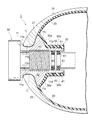
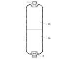
図2は、高圧タンク1の要部を示す断面図である。高圧タンク1は、例えば両端が略半球状である円筒形状のタンク本体10と、当該タンク本体10の長手方向の一端部に取り付けられた口金部11を有する。
FIG. 2 is a cross-sectional view showing a main part of the high-
タンク本体10は、例えば二層構造の壁層を有し、内壁層であるライナ20とその外側の外壁層である樹脂繊維層(補強層)としての例えばCFRP層21を有している。
The
ライナ20は、タンク本体10とほぼ同じ形状に形成される。ライナ20は、例えばポリエチレン樹脂、ポリプロピレン樹脂、またはその他の硬質樹脂などにより形成されている(以下、樹脂ライナ20ともいう)。
The
樹脂ライナ20の口金部11のある先端側には、内側に屈曲した折返し部30が形成されている。折返し部30は、外側のCFRP層21から離間するようにタンク本体10の内側に向けて折り返されている。折返し部30は、例えば折り返しの先端に近づくにつれて次第に径が小さくなる縮径部30aと、当該縮径部30aの先端に接続され径が一定の円筒部30bとを有している。この円筒部30bにより樹脂ライナ20の開口部が形成されている。
A folded
口金部11は、略円筒形状を有し、樹脂ライナ20の開口部に嵌入されている。口金部11は、例えばアルミニウム又はアルミニウム合金からなり、例えばダイキャスト法等により所定の形状に製造されている。口金部11は、例えばインサート成形により樹脂ライナ20に取り付けられている。
The
口金部11は、例えば先端側(高圧タンク1の軸方向の外側)に鍔部11aが形成され、例えばその鍔部11aの後方側(高圧タンク1の軸方向の内側)に、高圧タンク1の軸に対して環状の凹み部11bが形成されている。凹み部11bは、軸側に凸に湾曲しR形状になっている。この凹み部11bには、同じくR形状のCFRP層21の先端部付近が気密に接触している。
The
例えばCFRP層21と接触する凹み部11bの表面には、例えばフッ素系の樹脂などの固体潤滑コーティングCが施されている。これにより、CFRP層21と凹み部11bとの間の摩擦係数が低減されている。
For example, the surface of the
口金部11の凹み部11bのさらに後方側は、例えば樹脂ライナ20の折返し部30の形状に適合するように形成され、例えば凹み部11bに連続して径の大きい突出部11cが形成され、その突出部11cから後方に一定径の口金部円筒部11dが形成されている。上記樹脂ライナ20の折返し部30の縮径部30aは、突出部11cの表面に密着し、円筒部30bは、口金部円筒部11dの表面に密着している。円筒部30bと口金部円筒部11dとの間には、シール部材40、41が介在されている。
The rear side of the recessed
口金部11の内周面には、バルブアッセンブリ50をねじ込み接続するためのねじ42が形成されている。バルブアッセンブリ50は、外部のガス供給ライン(供給路22)と高圧タンク1の内部との間で燃料ガスの給排を制御するものである。バブルアッセンブリ50の外周面と口金部11の内周面との間には、シール部材60、61が介在されている。
A
CFRP層21は、例えばFW成形(フィラメントワインディング成形)により、樹脂ライナ20の外周面と口金部11の凹み部11bに、樹脂の含浸した補強繊維を巻き付け、当該樹脂を硬化させることにより形成されている。CFRP層21の樹脂には、例えばエポキシ樹脂、変性エポキシ樹脂、不飽和ポリエステル樹脂等が用いられる。また、補強繊維としては、炭素繊維、金属繊維などが用いられる。
The
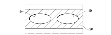
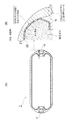
ここで、本実施形態の高圧タンク1を構成する樹脂ライナ20には、当該樹脂ライナ20の板厚内に、当該高圧タンク1の軸方向に沿って延びる複数の中空部(中空孔)19がガスインジェクションなどにより形成されている(図6等参照)。また、これら中空部19は、その一端が例えば後述するゲート切断部の開口部に連通するなど、口金部11の付近においてガス排出口を有するように形成されている。
Here, the
このように構成された高圧タンク1においては、樹脂ライナ20を透過した水素ガスの一部またはその多くが上述の中空部19により捕捉され、当該樹脂ライナ20とCFRP層21との間に溜まる前にタンク外部へと排出される。このため、これら中空部19は、樹脂ライナ20を透過した水素ガスを捕捉してタンク外部に排出可能とする、いわばリークポートとしての機能を発揮しうる。しかも、このような中空部19を形成することにより樹脂ライナ20の軽量化を図ることができる。また、中空部19を備えることにより、樹脂ライナ20の重量あたりの強度が向上することになり、場合によっては中空となることで中実のときよりも強度自体が向上することもある。
In the high-
なお、樹脂ライナ20を透過した水素ガスをより多くの箇所で効率的に捕捉して排出するという点からすれば、これら中空部19は、タンク胴部から口金部11の付近まで樹脂ライナ20の全長にわたり連続して形成されていることが好ましい。また、中空部19は、樹脂ライナ20の必要な強度が確保される範囲で多く設けられていることが好ましく、さらに樹脂ライナ20の周方向に等間隔に形成されていることがより好ましい。
From the viewpoint of efficiently capturing and discharging the hydrogen gas that has passed through the
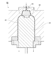
続いて、このような高圧タンク1の製造方法について以下に説明する(図3、図9参照)。
Then, the manufacturing method of such a
まず、射出成形用金型80のコア(雄型)81と主型(雌型)82との間に形成されるキャビティに対し、射出用のゲート83から樹脂を注入する(ステップSP1)。このような樹脂ライナ20の成形中、ゲート83を経由して不活性ガス等の加圧ガスを注入するとともにコア81を後退させてキャビティを徐々に拡大し(ステップSP2)、所定時間ガス圧力を保持しつつ冷却して固化させる(ステップSP3)。その後、加圧ガスをタンク外に排出させ、回収する(ステップSP4)。加圧ガスは、例えば金型80の下部(ゲート83とは反対の側)等から排出することができる。なお、図3中では、成形品取出し後に削除される成形用ランナー部およびゲート部を破線で囲んで示している(図3参照)。
First, resin is injected from the
以上により、樹脂ライナ20にタンク軸方向に沿って複数の中空部19が形成される。なお、樹脂を注入しながら加圧ガスを注入し、キャビティを拡大させることが好ましい。また、本明細書では軸方向に沿って、と説明しているが、これは中空部19の一端から他端まで軸方向と平行な直線になっているということではなく、本実施形態の中空部19はあくまで高圧タンク1の形状に沿って(口金部11付近の半球部分においては湾曲した状態で)形成されている。
Thus, a plurality of
なお、加圧ガスの注入による中空部19の形成は、いわゆるガスインジェクション成形法を利用して行うことができる。ガスインジェクション用の装置は、例えば一般の射出成形機の他にガスボンベまたは高圧ガス発生装置とガス注入装置を備え、金型にはガス注入部が設けられているものである。またガスインジェクション成形の一般的な工程においては、金型内に溶融樹脂を射出した後ノズルやランナー部、またはキャビティに直接不活性ガスを注入することにより中空構造の成形品が得られる。ガスインジェクション成形法の基本原理は、金型内に溶融樹脂を射出した後、樹脂中に不活性ガスを注入しながら金型の雌雄一方の側を移動させ、金型のキャビティ容積を拡大して高中空成形品を得るというものである。
In addition, formation of the
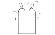
次に、中空部19が形成された樹脂ライナ20を、十分に冷却した後で金型80から取り出す(ステップSP5)。さらに、取り出した樹脂ライナ20のランナー部分やゲート部分(図4において符号20gで示す)を切断する(ステップSP6)。樹脂ライナ20のゲート部分20gを切断することにより、高圧タンク1の使用時において水素ガス等をタンク外へと排出するための排出口が形成される(図4等参照)。なお、特に詳しくは図示していないが、本実施形態の高圧タンク1においては図4中の矢示している部分の付近に排出口が形成される。
Next, the
その後、2つの樹脂ライナ20の開口端どうしを突き合わせた状態で溶着し、口金部11を組み付け(図7参照)、FW(フィラメントワインディング)成形を行う(図8参照)。FW成形後、当該高圧タンク1を加熱硬化して完成品を得る(ステップSP7〜9)。
Thereafter, the two
このようにして形成される高圧タンク1おいては、樹脂ライナ20に形成された中空部19が漏れガスを排出するいわばリークポートとして機能しうる。
In the high-
一方、樹脂ライナ20とCFRP層21のみからなる従来構造の高圧タンクの場合、樹脂ライナ20を透過した水素ガスが当該樹脂ライナ20とその外側の補強層(本実施形態の場合、CFRP層21)との間に滞留し、水素ガス放出時に樹脂ライナ20が内側に変形することがある(図10〜図12参照)。このように水素ガス放出時に変形した樹脂ライナ20は、水素ガス充填時には再度圧力に押されて元に戻り、水素ガスが再放出されれば再び内側に変形してしまい、これを繰り返すうちにやがて破損に至る場合がある(図11参照)。また、水素ガスが樹脂ライナ20と補強層(CFRP層21)との間に滞留しているとき、高圧タンク1内が高圧であればCFRP層21と口金部11との間が加圧されてシールされた状態にあるため水素ガスは滞留したままであるが、水素ガスが使用される等して内圧が下がると、シールが弱まったCFRP層21と口金部11との間から水素ガスがタンク外へと漏れてしまう場合がある(図12参照)。
On the other hand, in the case of a conventional high-pressure tank consisting only of the
これに対し、上述のように樹脂ライナ20に形成された中空部19が漏れガスを排出するいわばリークポートとして機能しうる本実施形態の高圧タンク1においては、当該樹脂ライナ20とCFRP層21との間に水素ガスが滞留するのを抑制することができる。しかも、本実施形態では樹脂ライナ20の内部に中空部19が形成された状態でFW成形を行うため、実際の使用時において、ライナ内側を透過した水素等のガスがこの中空部19を通り、口金部11の付近よりタンク外へと排出される。また、中空構造のため、ライナ強度が向上し、いわゆる内凹などの変形が生ずるのを抑制することにも繋がる。
In contrast, in the high-
なお、上述の実施形態は本発明の好適な実施の一例ではあるがこれに限定されるものではなく本発明の要旨を逸脱しない範囲において種々変形実施可能である。例えば上述した各実施形態では中空部19の大きさや数について説明しなかったが、これら大きさや数が特に限定されることはない。また、例えば加圧ガス注入口(ゲート83)の数、樹脂ライナ20の断面積、注入ガスの圧力などを変更することにより、中空部19の大きさや数は適宜調整することが可能である。
The above-described embodiment is an example of a preferred embodiment of the present invention, but is not limited thereto, and various modifications can be made without departing from the scope of the present invention. For example, in each embodiment mentioned above, although the magnitude | size and number of the
さらに、ここまでの実施形態では、高圧タンク1が燃料電池システム100における燃料供給源としての水素タンクである場合について説明したが、これも本発明の好適な形態例にすぎず、本発明にかかる高圧タンク1を水素ガス以外のガスに適用することも可能である。
Further, in the embodiments so far, the case where the high-
また、ここまで、口金部として符号11で示すものを例示して本実施形態を説明してきたが、本発明でいうところの口金部は、バルブアッセンブリ50が取り付けられるものに限らない。すなわち、高圧タンク1におけるバルブアッセンブリ50の反対側に例えばボスが設けられる場合、当該ボスが取り付けられる口金部も本発明でいうところの口金部に該当する。なお、図7および図10においては、ボスが取り付けられる口金部を符号18で示している。
In addition, heretofore, the present embodiment has been described by exemplifying what is denoted by
1…高圧タンク(ガスタンク)、11…口金部、18…口金部、19…中空部、20…樹脂ライナ(ライナ)、21…CFRP層(FRP)、80…金型、81…コア、82…主型、83…ゲート
DESCRIPTION OF
Claims (6)
ライナ板厚内であって、当該タンクの軸方向に沿って中空部が形成されているガスタンク。 In the gas tank composed of liner and FRP,
A gas tank in which a hollow portion is formed in the liner plate thickness along the axial direction of the tank.
射出成形用金型の主型とコアとの間に形成されるキャビティに対して射出用のゲートから樹脂を注入し、当該樹脂製のライナの成形中に、前記ゲートを経由して不活性ガス等の加圧ガスを注入し、前記コアの一部を後退させて前記キャビティを拡大し、所定期間ガス圧力を保持しつつ冷却して固化させた後、前記加圧ガスを前記金型の外部に排出して回収する、ガスタンクの製造方法。 In the method of manufacturing a gas tank composed of a liner and FRP,
Resin is injected from the injection gate into the cavity formed between the main mold of the injection mold and the core, and the inert gas passes through the gate during molding of the resin liner. After injecting a pressurized gas such as a part, the part of the core is retracted to enlarge the cavity, and cooled and solidified while maintaining the gas pressure for a predetermined period, and then the pressurized gas is supplied to the outside of the mold. A method of manufacturing a gas tank that is discharged and collected.
Priority Applications (3)
| Application Number | Priority Date | Filing Date | Title |
|---|---|---|---|
| JP2008244131A JP4775776B2 (en) | 2008-09-24 | 2008-09-24 | Gas tank and manufacturing method thereof |
| DE102009042553.5A DE102009042553B4 (en) | 2008-09-24 | 2009-09-22 | Gas tank and method for producing a gas tank liner |
| US12/565,373 US8906287B2 (en) | 2008-09-24 | 2009-09-23 | Gas tank and method of manufacturing liner for gas tank |
Applications Claiming Priority (1)
| Application Number | Priority Date | Filing Date | Title |
|---|---|---|---|
| JP2008244131A JP4775776B2 (en) | 2008-09-24 | 2008-09-24 | Gas tank and manufacturing method thereof |
Publications (2)
| Publication Number | Publication Date |
|---|---|
| JP2010077995A true JP2010077995A (en) | 2010-04-08 |
| JP4775776B2 JP4775776B2 (en) | 2011-09-21 |
Family
ID=42036583
Family Applications (1)
| Application Number | Title | Priority Date | Filing Date |
|---|---|---|---|
| JP2008244131A Expired - Fee Related JP4775776B2 (en) | 2008-09-24 | 2008-09-24 | Gas tank and manufacturing method thereof |
Country Status (3)
| Country | Link |
|---|---|
| US (1) | US8906287B2 (en) |
| JP (1) | JP4775776B2 (en) |
| DE (1) | DE102009042553B4 (en) |
Cited By (6)
| Publication number | Priority date | Publication date | Assignee | Title |
|---|---|---|---|---|
| CN102218810A (en) * | 2010-02-26 | 2011-10-19 | 通用汽车环球科技运作有限责任公司 | Method for producing a liner of a vessel |
| JP2014081014A (en) * | 2012-10-15 | 2014-05-08 | Honda Motor Co Ltd | Pressure gas container and vehicle including the same |
| DE102014005606A1 (en) | 2013-04-17 | 2014-10-23 | Toyoda Gosei Co., Ltd. | Pressure vessel lining, associated mold and pressure vessel |
| JP2015085946A (en) * | 2013-10-30 | 2015-05-07 | 横浜ゴム株式会社 | Aircraft water tank |
| JP2015132307A (en) * | 2014-01-10 | 2015-07-23 | 株式会社Fts | Mouthpiece structure of pressure container |
| US11473727B2 (en) | 2019-06-28 | 2022-10-18 | Honda Motor Co., Ltd. | High pressure gas container |
Families Citing this family (13)
| Publication number | Priority date | Publication date | Assignee | Title |
|---|---|---|---|---|
| US9618160B2 (en) | 2009-02-06 | 2017-04-11 | Hexagon Technology As | Pressure vessel longitudinal vents |
| AT11704U1 (en) * | 2009-06-15 | 2011-03-15 | Magna Steyr Fahrzeugtechnik Ag | PRESSURE VESSELS FOR GASEOUS OR LIQUID MEDIA |
| WO2012074815A2 (en) * | 2010-11-29 | 2012-06-07 | Mark Leavitt | Breather layer for exhausting permeate from pressure vessels |
| US9545770B2 (en) * | 2014-04-17 | 2017-01-17 | The Boeing Company | Dis-bond membrane for a lined pressure vessel |
| BR112018068782B1 (en) | 2016-03-16 | 2024-02-15 | Hexagon Technology As | APPARATUS FOR PRESSURE VESSEL, PRESSURE VESSEL AND METHOD FOR FORMING A PRESSURE VESSEL |
| JP7044003B2 (en) * | 2018-07-25 | 2022-03-30 | トヨタ自動車株式会社 | High pressure tank |
| US11047530B2 (en) | 2018-10-30 | 2021-06-29 | GM Global Technology Operations LLC | Pressure vessel having grooved liner |
| JP6800254B2 (en) * | 2019-01-25 | 2020-12-16 | 本田技研工業株式会社 | Fuel gas filling method |
| US11143362B2 (en) | 2019-07-09 | 2021-10-12 | GM Global Technology Operations LLC | Storage tank for pressurized gas and method of manufacturing same |
| US11299036B2 (en) | 2019-11-06 | 2022-04-12 | GM Global Technology Operations LLC | Hydrogen storage tank having a nanoporous breather layer |
| JP7555306B2 (en) * | 2021-06-08 | 2024-09-24 | 本田技研工業株式会社 | High pressure tank and manufacturing method thereof |
| DE102023200073A1 (en) * | 2023-01-05 | 2024-07-11 | Stellantis Auto Sas | Procedure for removing foreign gas |
| CN120101034B (en) * | 2025-04-02 | 2025-11-14 | 中国特种设备检测研究院 | Hydrogen storage cylinder with anti-bend inner liner |
Citations (6)
| Publication number | Priority date | Publication date | Assignee | Title |
|---|---|---|---|---|
| JPS63128381U (en) * | 1987-02-16 | 1988-08-22 | ||
| JPH04357009A (en) * | 1991-01-30 | 1992-12-10 | Asahi Chem Ind Co Ltd | Hollow injection-molded article and hollow injection molding method and mold |
| JPH07305798A (en) * | 1994-05-12 | 1995-11-21 | Nippon Ekosu Kk | Pressure vessel made of plastic |
| JPH11210988A (en) * | 1998-01-23 | 1999-08-06 | Honda Motor Co Ltd | Base structure of compressed natural gas container |
| JP2004176885A (en) * | 2002-11-29 | 2004-06-24 | Mitsubishi Heavy Ind Ltd | Hydrogen storage container |
| JP2008190699A (en) * | 2007-02-07 | 2008-08-21 | Toyota Motor Corp | Fuel cell system and fuel gas tank |
Family Cites Families (6)
| Publication number | Priority date | Publication date | Assignee | Title |
|---|---|---|---|---|
| US3648886A (en) * | 1970-05-11 | 1972-03-14 | William L Pringle | Fuel tank assembly |
| WO1992013699A1 (en) * | 1991-01-30 | 1992-08-20 | Asahi Kasei Kogyo Kabushiki Kaisha | Mold for injection blow molding, method of blow molding, and metallic mold |
| US5656234A (en) * | 1994-08-12 | 1997-08-12 | Mitsubishi Gas Chemical Company, Inc. | Mold apparatus and injection molding method for producing hollow-structured article by injection molding |
| JP3523802B2 (en) * | 1999-04-07 | 2004-04-26 | 豊田合成株式会社 | Pressure vessel |
| JP2006316934A (en) * | 2005-05-13 | 2006-11-24 | Nissan Motor Co Ltd | High pressure gas storage container |
| DE102006006902B4 (en) * | 2006-02-09 | 2008-02-21 | Gräfenthaler Kunststofftechnik GmbH | Plastic pressure vessel and process for its manufacture |
-
2008
- 2008-09-24 JP JP2008244131A patent/JP4775776B2/en not_active Expired - Fee Related
-
2009
- 2009-09-22 DE DE102009042553.5A patent/DE102009042553B4/en not_active Expired - Fee Related
- 2009-09-23 US US12/565,373 patent/US8906287B2/en active Active
Patent Citations (6)
| Publication number | Priority date | Publication date | Assignee | Title |
|---|---|---|---|---|
| JPS63128381U (en) * | 1987-02-16 | 1988-08-22 | ||
| JPH04357009A (en) * | 1991-01-30 | 1992-12-10 | Asahi Chem Ind Co Ltd | Hollow injection-molded article and hollow injection molding method and mold |
| JPH07305798A (en) * | 1994-05-12 | 1995-11-21 | Nippon Ekosu Kk | Pressure vessel made of plastic |
| JPH11210988A (en) * | 1998-01-23 | 1999-08-06 | Honda Motor Co Ltd | Base structure of compressed natural gas container |
| JP2004176885A (en) * | 2002-11-29 | 2004-06-24 | Mitsubishi Heavy Ind Ltd | Hydrogen storage container |
| JP2008190699A (en) * | 2007-02-07 | 2008-08-21 | Toyota Motor Corp | Fuel cell system and fuel gas tank |
Cited By (9)
| Publication number | Priority date | Publication date | Assignee | Title |
|---|---|---|---|---|
| CN102218810A (en) * | 2010-02-26 | 2011-10-19 | 通用汽车环球科技运作有限责任公司 | Method for producing a liner of a vessel |
| JP2014081014A (en) * | 2012-10-15 | 2014-05-08 | Honda Motor Co Ltd | Pressure gas container and vehicle including the same |
| DE102014005606A1 (en) | 2013-04-17 | 2014-10-23 | Toyoda Gosei Co., Ltd. | Pressure vessel lining, associated mold and pressure vessel |
| US9377162B2 (en) | 2013-04-17 | 2016-06-28 | Toyoda Gosei Co., Ltd. | Pressure vessel liner, molding die thereof, and pressure vessel |
| DE102014005606B4 (en) | 2013-04-17 | 2018-06-07 | Toyoda Gosei Co., Ltd. | Pressure vessel lining, associated mold and pressure vessel |
| JP2015085946A (en) * | 2013-10-30 | 2015-05-07 | 横浜ゴム株式会社 | Aircraft water tank |
| WO2015064424A1 (en) * | 2013-10-30 | 2015-05-07 | 横浜ゴム株式会社 | Aircraft water tank |
| JP2015132307A (en) * | 2014-01-10 | 2015-07-23 | 株式会社Fts | Mouthpiece structure of pressure container |
| US11473727B2 (en) | 2019-06-28 | 2022-10-18 | Honda Motor Co., Ltd. | High pressure gas container |
Also Published As
| Publication number | Publication date |
|---|---|
| US8906287B2 (en) | 2014-12-09 |
| US20100072209A1 (en) | 2010-03-25 |
| JP4775776B2 (en) | 2011-09-21 |
| DE102009042553B4 (en) | 2017-06-29 |
| DE102009042553A1 (en) | 2010-05-12 |
Similar Documents
| Publication | Publication Date | Title |
|---|---|---|
| JP4775776B2 (en) | Gas tank and manufacturing method thereof | |
| JP2010071444A (en) | High pressure tank, manufacturing method for the same and manufacturing equipment | |
| JP5071801B2 (en) | High pressure tank and manufacturing method thereof | |
| US9261239B2 (en) | Pressure gas container and vehicle including the same | |
| US9774047B2 (en) | Method and apparatus for forming a matrix liner for a pressure vessel | |
| CN102213314B (en) | For the temperature-adjusting device of pressurized container | |
| KR102322373B1 (en) | High-pressure tank having hoop layers and helical layers | |
| US20090152278A1 (en) | Inner shell for a pressure vessel | |
| US8517199B2 (en) | High-pressure tank with separate product and pressure testing screw sections | |
| JP7040425B2 (en) | Manufacturing method of high pressure tank | |
| KR102298962B1 (en) | High-pressure tank for enabling radation of heat and discharging permeated gas from thereof and the method for the same | |
| JP2009243675A (en) | Gas discharge volume control device stagnant gas discharging device | |
| JP5769088B2 (en) | High pressure tank | |
| JP2019116926A (en) | tank | |
| DE102017205190A1 (en) | Pressure vessel with fuel-impermeable liner | |
| US11654607B2 (en) | Method for manufacturing high pressure tank | |
| KR102322371B1 (en) | Pressure vessel including reinforced cylinder part | |
| KR101755927B1 (en) | Non-cylinder type composite pressure vessel of vehicle | |
| CN112413391B (en) | High-pressure storage tank | |
| JP6475077B2 (en) | Manufacturing method of pressure vessel liner | |
| JP2020118288A (en) | Hydrogen tank | |
| KR101655719B1 (en) | Fuel gas tank and manufacturing method its | |
| CN117489969B (en) | Hydrogen storage cylinder | |
| KR20190057482A (en) | High-pressure tank having curved-shaped liner |
Legal Events
| Date | Code | Title | Description |
|---|---|---|---|
| A977 | Report on retrieval |
Free format text: JAPANESE INTERMEDIATE CODE: A971007 Effective date: 20100727 |
|
| A131 | Notification of reasons for refusal |
Free format text: JAPANESE INTERMEDIATE CODE: A131 Effective date: 20100805 |
|
| A521 | Request for written amendment filed |
Free format text: JAPANESE INTERMEDIATE CODE: A523 Effective date: 20101004 |
|
| A131 | Notification of reasons for refusal |
Free format text: JAPANESE INTERMEDIATE CODE: A131 Effective date: 20101110 |
|
| A521 | Request for written amendment filed |
Free format text: JAPANESE INTERMEDIATE CODE: A523 Effective date: 20110106 |
|
| A131 | Notification of reasons for refusal |
Free format text: JAPANESE INTERMEDIATE CODE: A131 Effective date: 20110216 |
|
| A521 | Request for written amendment filed |
Free format text: JAPANESE INTERMEDIATE CODE: A523 Effective date: 20110408 |
|
| TRDD | Decision of grant or rejection written | ||
| A01 | Written decision to grant a patent or to grant a registration (utility model) |
Free format text: JAPANESE INTERMEDIATE CODE: A01 Effective date: 20110606 |
|
| A01 | Written decision to grant a patent or to grant a registration (utility model) |
Free format text: JAPANESE INTERMEDIATE CODE: A01 |
|
| R151 | Written notification of patent or utility model registration |
Ref document number: 4775776 Country of ref document: JP Free format text: JAPANESE INTERMEDIATE CODE: R151 |
|
| A61 | First payment of annual fees (during grant procedure) |
Free format text: JAPANESE INTERMEDIATE CODE: A61 Effective date: 20110619 |
|
| FPAY | Renewal fee payment (event date is renewal date of database) |
Free format text: PAYMENT UNTIL: 20140708 Year of fee payment: 3 |
|
| LAPS | Cancellation because of no payment of annual fees |