JP2010084792A - Vibration isolating device - Google Patents
Vibration isolating device Download PDFInfo
- Publication number
- JP2010084792A JP2010084792A JP2008251538A JP2008251538A JP2010084792A JP 2010084792 A JP2010084792 A JP 2010084792A JP 2008251538 A JP2008251538 A JP 2008251538A JP 2008251538 A JP2008251538 A JP 2008251538A JP 2010084792 A JP2010084792 A JP 2010084792A
- Authority
- JP
- Japan
- Prior art keywords
- longitudinal direction
- portions
- bracket
- rubber elastic
- vibration isolator
- Prior art date
- Legal status (The legal status is an assumption and is not a legal conclusion. Google has not performed a legal analysis and makes no representation as to the accuracy of the status listed.)
- Granted
Links
Images






Landscapes
- Arrangement Or Mounting Of Propulsion Units For Vehicles (AREA)
- Vibration Prevention Devices (AREA)
- Springs (AREA)
Abstract
【課題】変速機を車体に防振支持させる防振装置において、部品点数等の増大を抑えつつ三方向で所望のバネ特性を得、変速機の脱落を抑えてフェールセーフを達成する。
【解決手段】下側及び上側取付金具3,5と支持ゴム弾性体7,7とを備えた防振装置1である。下側取付金具3は、クロスメンバに取り付けられる下側水平部3aと、下側水平部3aから斜め上方に延びる下側傾斜部3b,3bとを有し、上側取付金具5は、上側水平部5aと、上側水平部5aから斜め上方に延びる上側傾斜部5b,5bと、上側傾斜部5b,5bから外側に延びトランスミッションに取り付けられる上側取付部5c,5cとを有している。各支持ゴム弾性体7,7は、上側傾斜部5b,5bと各下側傾斜部3b,3bとを連結し、各下側傾斜部3b,3bには断面逆V字状の下側補強部35が、各上側傾斜部5b,5bには支持ゴム弾性体7,7を挟む上側補強部37が設けられている。
【選択図】図1In a vibration isolator that supports a transmission on a vehicle body in a vibration isolating manner, desired spring characteristics are obtained in three directions while suppressing an increase in the number of parts and the like, and a fail safe is achieved by suppressing a dropout of the transmission.
A vibration isolator is provided with lower and upper mounting brackets (3, 5) and support rubber elastic bodies (7, 7). The lower mounting bracket 3 includes a lower horizontal portion 3a attached to the cross member, and lower inclined portions 3b and 3b extending obliquely upward from the lower horizontal portion 3a. The upper mounting bracket 5 includes an upper horizontal portion. 5a, upper inclined portions 5b, 5b extending obliquely upward from the upper horizontal portion 5a, and upper mounting portions 5c, 5c extending outward from the upper inclined portions 5b, 5b and attached to the transmission. Each support rubber elastic body 7, 7 connects the upper inclined portions 5 b, 5 b and the lower inclined portions 3 b, 3 b, and the lower inclined portions 3 b, 3 b have lower V-shaped cross-sectional lower reinforcing portions. 35 is provided with an upper reinforcing portion 37 that sandwiches the supporting rubber elastic bodies 7 and 7 in the upper inclined portions 5b and 5b.
[Selection] Figure 1
Description
本発明は、防振装置に関し、特に、変速機を車体に対して防振支持させる防振装置に関するものである。 The present invention relates to a vibration isolator, and more particularly, to a vibration isolator that supports a transmission with respect to a vehicle body.
従来から、トランスミッション(変速機)を支持するようにクロスメンバ等の車体フレームに取り付けられ、トランスミッションからの振動を車体に伝えないように減衰させるとともに、上下方向、車両前後方向及び車幅方向でストッパとして機能する防振装置が知られている。 Conventionally, it is attached to a vehicle body frame such as a cross member so as to support a transmission (transmission), and attenuates vibrations from the transmission so as not to be transmitted to the vehicle body, and has a stopper in the vertical direction, the vehicle longitudinal direction, and the vehicle width direction. An anti-vibration device functioning as is known.
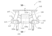
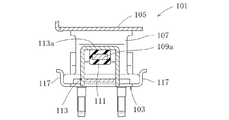
例えば、特許文献1には、図11及び図12に示すように、三方向でストッパとして機能する防振装置が開示されている。この防振装置101は、鉄製の長方形の平板である上板金具105と、上板金具105の下面の長手方向の両端側に固定されて下方に突出した略U字状の係合金具109と、上板金具105に対して係合金具109を挟んで所定距離を隔てて対向配置された下板金具103と、下板金具103の長手方向中間位置にて立設されて係合金具109の底板109aを囲む第2係合金具113と、上板金具105の下面の両端側にそれぞれ接着されて下板金具103に向けて延び、各先端部分が下板金具103の各保持部103a,103aに圧入により嵌合固定されて上板金具105及び下板金具103間を弾性的に連結する一対の支持ゴム弾性体107,107と、支持ゴム弾性体107,107と一体で形成されて係合金具109の底板109aの表面を被覆するゴム弾性体被覆部111とにより構成されている。
For example,
この防振装置101では、上方に大きな荷重が入力すると、第2係合金具113の水平板部113aが係合金具109の底板109aに当接することにより、支持ゴム弾性体107,107の上方への過大な変位が抑えられるようになっている。また、支持ゴム弾性体107,107の長手方向及び幅方向への移動は、第1係止片115,115及び第2係止片117,117によって確実に抑えられるように構成されている。
ところで、互いに平行な取付板間にゴム弾性体を挟着してなる防振ゴムでは、圧縮剛性に比してせん断剛性が非常に小さい(柔らかい)バネ特性となっているが、例えば、変速機が車体に対しローリング方向に大きく振動して車幅方向に大きな荷重が入力した場合や、車両が急停車又は急発進したときの変速機の慣性力により車両前後方向に大きな荷重が入力した場合を考慮して、防振装置に対して上下方向、車幅方向及び車両前後方向のバネ特性として2:1:1という比率が要求されることがある。 By the way, an anti-vibration rubber in which a rubber elastic body is sandwiched between mounting plates parallel to each other has a spring characteristic in which shear rigidity is very small (soft) as compared with compression rigidity. Considering when a large load is input in the vehicle width direction due to large vibration in the rolling direction with respect to the vehicle body, or when a large load is input in the vehicle longitudinal direction due to the inertial force of the transmission when the vehicle suddenly stops or starts suddenly Thus, a ratio of 2: 1: 1 may be required as a spring characteristic in the vertical direction, the vehicle width direction, and the vehicle longitudinal direction with respect to the vibration isolator.
ここで、特許文献1のものは、上下方向及び長手方向(車幅方向)では、支持ゴム弾性体107,107の角度を調整して支持ゴム弾性体107,107に圧縮方向の荷重を作用させることにより、高いバネ特性を得ることができるが、上下方向と長手方向とに直交する長手直角方向(車両前後方向)では、支持ゴム弾性体107,107の角度を調整しても、せん断方向の荷重が作用することから、高いバネ特性を得ることが困難になるという問題がある。また、長手直角方向において高いバネ特性を得るために支持ゴム弾性体107,107を大きくすると、防振装置101が大型化するという問題がある。
Here, the thing of
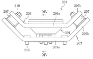
このような問題を解決するために、図13及び図14に示すような防振装置201を用いることが考えられる。この防振装置201は、平面視略長方形状に形成されていて、ボルト215により車体に取り付けられる下側水平部203aと、該下側水平部203aの長手方向両端部から外側に行くに従って上方に延びる一対の下側傾斜部203b,203bとを有している下側取付金具203と、上側水平部205aと該上側水平部205aの長手方向両端部から外側に行くに従って上方に延び、ボルト219により変速機に取り付けられる一対の上側傾斜部205b,205bとを有し、下側取付金具203と対向配置されている上側取付金具205と、一対の上側傾斜部205b,205bと一対の下側傾斜部203b,203bとをそれぞれ連結している一対の支持ゴム弾性体207,207とを備えているとともに、上下方向と長手方向とに直交する長手直角方向のバネ特性を高めるためのゴム弾性体307を有する防振マウント301をさらに備えている。
In order to solve such a problem, it is conceivable to use a
この防振装置201によれば、上下方向、長手方向及び長手直角方向で高いバネ特性を得ることができるが、製造工程及び部品点数の増大し、生産性が低下するという問題がある。
According to the
さらに、この防振装置では、防振マウントは長手直角方向の支持ゴムとしての機能しか有しないことから、万が一支持ゴム弾性体207,207が破断した場合には、トランスミッションが大きく傾いて脱落するおそれがある。
Further, in this vibration isolator, since the vibration isolating mount has only a function as a support rubber in the direction perpendicular to the longitudinal direction, if the support rubber
本発明は、かかる点に鑑みてなされたものであり、その目的とするところは、変速機を車体に対して防振支持させる防振装置において、製造工程及び部品点数の増大を抑えつつ三方向で要求される高いバネ特性を得るとともに、変速機の脱落を確実に抑えてフェールセーフを達成する技術を提供することにある。 The present invention has been made in view of the above points, and an object of the present invention is to provide a vibration isolator that supports the transmission with respect to the vehicle body in three directions while suppressing an increase in the manufacturing process and the number of parts. It is an object of the present invention to provide a technology that achieves fail-safeness while ensuring the high spring characteristics required in the above-mentioned method and reliably suppressing the dropout of the transmission.
第1の発明は、長尺物の金具であって、車体に取り付けられる下側水平部と、該下側水平部の金具長手方向両端部から金具長手方向外側に行くに従って上方に傾斜して延びている一対の下側傾斜部とを有している下側取付金具と、中央に上下方向に延びる貫通孔が形成されている上側水平部と、該上側水平部の金具長手方向両端部から金具長手方向外側に行くに従って上方に傾斜して延びている一対の上側傾斜部と、該上側傾斜部の金具長手方向両端部から金具長手方向外側に延びていて変速機に取り付けられる上側取付部とを有し、上記下側取付金具と対向配置されている上側取付金具と、上記各上側傾斜部と上記各下側傾斜部とをそれぞれ連結している一対の支持ゴム弾性体と、上記貫通孔の内周面及び周縁部を覆うように上記上側水平部に形成されている環状のストッパラバーと、上記環状のストッパラバーとその径方向に所定間隔を空けて該ストッパラバーを貫通しているストッパピンと、上記上側水平部の上方で上記ストッパピンに取り付けられているストッパプレートと、上記ストッパピンの下端部が固定され、上記下側水平部に取り付けられている架台とを備えており、上記各下側傾斜部には、該各下側傾斜部の傾斜方向に延び、上記各支持ゴム弾性体の下端部を切り欠くように該傾斜方向から見て断面略逆V字状に形成されている補強本体部を有する下側補強部がそれぞれ設けられている一方、上記各上側傾斜部には、上下方向と金具長手方向とに直交する金具長手直角方向から上記各支持ゴム弾性体の上端部を挟むように形成されている上側補強部がそれぞれ設けられていることを特徴とするものである。 1st invention is a metal fitting of a long thing, and it inclines upwards as it goes to the metal plate longitudinal direction outside from the metal plate longitudinal direction both ends attached to a vehicle body, and the lower horizontal part. A lower mounting bracket having a pair of lower inclined portions, an upper horizontal portion in which a through-hole extending in the vertical direction is formed in the center, and a bracket from both ends of the upper horizontal portion in the longitudinal direction of the bracket A pair of upper inclined portions extending obliquely upward as going outward in the longitudinal direction, and an upper mounting portion extending from the both ends of the upper inclined portion in the longitudinal direction of the bracket to the outer side in the longitudinal direction of the bracket and attached to the transmission An upper mounting bracket disposed opposite to the lower mounting bracket, a pair of support rubber elastic bodies respectively connecting the upper inclined portions and the lower inclined portions, and the through holes The upper horizontal so as to cover the inner peripheral surface and peripheral edge An annular stopper rubber formed on the annular stopper rubber, a stopper pin passing through the stopper rubber with a predetermined interval in the radial direction thereof, and an upper stopper attached to the stopper pin above the upper horizontal portion. A stopper plate, and a base attached to the lower horizontal portion, the lower end portion of the stopper pin being fixed, and each lower inclined portion includes an inclination of each lower inclined portion. A lower reinforcing portion having a reinforcing main body portion extending in a direction and having a substantially V-shaped cross section when viewed from the inclined direction so as to cut out the lower end portion of each of the supporting rubber elastic bodies is provided. On the other hand, each upper inclined portion is provided with an upper reinforcing portion formed so as to sandwich the upper end portion of each supporting rubber elastic body from the vertical direction of the bracket perpendicular to the vertical direction and the longitudinal direction of the bracket. And it is characterized in that it is.
第1の発明によれば、各支持ゴム弾性体は、上側取付金具の各上側傾斜部と下側取付金具の各下側傾斜部とをそれぞれ連結しているので、各傾斜部の角度を調整して各支持ゴム弾性体に圧縮方向の荷重を作用させることで、上下方向及び金具長手方向における防振装置のバネ特性を高く設定することができる。 According to the first invention, each supporting rubber elastic body connects each upper inclined portion of the upper mounting bracket and each lower inclined portion of the lower mounting bracket, so that the angle of each inclined portion is adjusted. By applying a load in the compression direction to each supporting rubber elastic body, the spring characteristics of the vibration isolator in the vertical direction and the metal fitting longitudinal direction can be set high.
また、各下側傾斜部には、該各下側傾斜部の傾斜方向に延び、各支持ゴム弾性体の下端部を切り欠くように該傾斜方向から見て断面逆V字状に形成されている下側補強部が設けられている一方、各上側傾斜部には、上下方向と金具長手方向とに直交する金具長手直角方向から各支持ゴム弾性体を挟むように形成されている上側補強部が設けられているので、簡単な構造でせん断方向の荷重を圧縮方向の荷重として各支持ゴム弾性体に作用させ、金具長手直角方向における防振装置のバネ特性を高く設定することができる。 Each lower inclined portion is formed in an inverted V-shaped cross section when viewed from the inclined direction so as to extend in the inclination direction of each lower inclined portion and cut out the lower end portion of each supporting rubber elastic body. On the other hand, each upper inclined portion is formed so as to sandwich each supporting rubber elastic body from the metal longitudinal direction perpendicular to the vertical direction and the metal longitudinal direction. Therefore, the spring characteristic of the vibration isolator can be set high in the direction perpendicular to the longitudinal direction of the metal fitting by applying a load in the shearing direction as a load in the compression direction to each supporting rubber elastic body with a simple structure.
さらに、上側取付金具の貫通孔をストッパピンが貫通しており、且つ上側取付金具がストッパプレートと架台によって上下方向に挟まれているので、万が一支持ゴム弾性体が破断した場合にも、変速機が大きく傾いて脱落するのを抑制することができる。 Further, since the stopper pin penetrates the through hole of the upper mounting bracket and the upper mounting bracket is sandwiched in the vertical direction by the stopper plate and the gantry, even if the support rubber elastic body is broken, the transmission Can be prevented from falling off with a large inclination.
したがって、製造工程及び部品点数の増大を抑えつつ三方向でそれぞれ所望のバネ特性を得るとともに、変速機の脱落を確実に抑えてフェールセーフを達成することができる。 Accordingly, desired spring characteristics can be obtained in each of the three directions while suppressing an increase in the number of manufacturing steps and the number of parts, and fail-safe can be achieved by reliably suppressing the dropout of the transmission.
第2の発明は、上記第1の発明において、上記各上側補強部は、上記傾斜方向から見て断面略逆U字状に形成され、該傾斜方向に延びていることを特徴とするものである。 A second invention is characterized in that, in the first invention, each of the upper reinforcing portions is formed in a substantially inverted U-shaped cross section when viewed from the inclined direction, and extends in the inclined direction. is there.
第2の発明によれば、各上側補強部は、傾斜方向から見て断面逆U字状に形成されているので、金具長手直角方向から各支持ゴム弾性体を挟むことができる。したがって、簡単な構造で、金具長手直角方向のバネ特性を高く設定することができる。 According to the second invention, each upper reinforcing portion is formed in an inverted U-shaped cross section when viewed from the inclined direction, so that each supporting rubber elastic body can be sandwiched from the direction perpendicular to the longitudinal direction of the metal fitting. Therefore, the spring characteristic in the direction perpendicular to the longitudinal direction of the bracket can be set high with a simple structure.
第3の発明は、上記第1の発明において、上記各上側補強部は、金具長手直角方向両端部における中央部が上記各下側傾斜部に向かって膨出していることにより、金具長手直角方向両端部が金具長手直角方向から見て断面略逆ハット状に形成されているとともに上記傾斜方向中央部が傾斜方向から見て断面略ハット状に形成されていることを特徴とするものである。 According to a third aspect of the present invention, in the first aspect of the present invention, each upper reinforcing portion has a central portion bulging toward the lower inclined portion at both ends in the bracket longitudinal direction, whereby the bracket longitudinal direction Both end portions are formed in a substantially inverted hat shape in cross section when viewed from the direction perpendicular to the longitudinal direction of the metal fitting, and the central portion in the inclined direction is formed in a substantially hat shape in cross section as viewed from the inclined direction.
第3の発明によれば、各上側補強部は、金具長手直角方向両端部が金具長手直角方向から見て断面逆ハット状をなすように上記各支持ゴム弾性体が延びる方向へ膨出しているので、これら両端部(エッジ)は金具長手直角方向に延びている。したがって、支持ゴム弾性体の成形用金型が金具長手直角方向と同じ方向に開閉する場合には、上側補強部のシール性を容易に確保することができる。 According to the third aspect of the present invention, each upper reinforcing portion bulges in the direction in which each of the supporting rubber elastic bodies extends so that both ends of the bracket in the direction perpendicular to the longitudinal direction of the metal have a reverse hat shape when viewed from the direction perpendicular to the longitudinal direction of the bracket. Therefore, these both end portions (edges) extend in the direction perpendicular to the metal fitting longitudinal direction. Therefore, when the molding die for the supporting rubber elastic body opens and closes in the same direction as the metallographic longitudinally perpendicular direction, the sealing property of the upper reinforcing portion can be easily ensured.
また、金具長手直角方向の両端部膨出することで、該各上側傾斜部の傾斜方向から見て断面略ハット状に形成されているので、金具長手直角方向から各支持ゴム弾性体を挟むことができる。したがって、防振装置の金具長手直角方向のバネ特性を高く設定することができる。 In addition, since both end portions in the direction perpendicular to the longitudinal direction of the metal fitting bulge, the support rubber elastic body is sandwiched from the direction perpendicular to the longitudinal direction of the metal fitting because the cross section is formed in a substantially hat shape when viewed from the inclination direction of each upper inclined portion. Can do. Therefore, the spring characteristics in the direction perpendicular to the longitudinal direction of the bracket of the vibration isolator can be set high.
さらに、各上側補強部は、金具長手直角方向及び傾斜方向の2方向で屈曲する形状に形成されているので、その耐久性を向上させることができる。 Furthermore, since each upper side reinforcement part is formed in the shape bent in two directions, a metal fitting longitudinal direction and an inclination direction, the durability can be improved.
第4の発明は、上記第3の発明において、上記各上側補強部は、上記各上側傾斜部を折り曲げ加工することにより形成されていることを特徴とするものである。 According to a fourth invention, in the third invention, each of the upper reinforcing portions is formed by bending each of the upper inclined portions.
第4の発明によれば、製造工程及び部品点数を減らしつつ、上記第3の発明と同様の効果を得ることができる。 According to the fourth invention, the same effects as in the third invention can be obtained while reducing the number of manufacturing steps and the number of parts.
第5の発明は、上記第1〜4のいずれか1つの発明において、上記下側及び上側取付金具は、金具長手方向が車幅方向と略一致するように、車体及び変速機にそれぞれ取り付けられることを特徴とするものである。 According to a fifth invention, in any one of the first to fourth inventions, the lower and upper mounting brackets are respectively attached to the vehicle body and the transmission such that the longitudinal direction of the bracket substantially coincides with the vehicle width direction. It is characterized by this.
第5の発明によれば、下側及び上側取付金具は、金具長手方向が車幅方向と略一致するように車体及び変速機に取り付けられているので、例えば、変速機が車体に対しローリング方向に大きく振動して車幅方向に大きな荷重が入力した場合にも、変速機と車体との相対振動を支持ゴム弾性体によって吸収することができる。 According to the fifth aspect of the present invention, the lower and upper mounting brackets are mounted on the vehicle body and the transmission so that the longitudinal direction of the bracket is substantially coincident with the vehicle width direction. For example, the transmission is in the rolling direction with respect to the vehicle body. Even when a large load is input in the vehicle width direction due to large vibrations, relative vibration between the transmission and the vehicle body can be absorbed by the support rubber elastic body.
さらに、各支持ゴム弾性体は、下側及び上側補強部により金具長手直角方向(車両前後方向)のバネ特性が高く設定されているので、例えば、車両が急停車したときや急発進したときのように、変速機の慣性力により車両前後方向に大きな荷重が入力した場合にも、変速機と車体との相対振動を支持ゴム弾性体によって吸収することができる。 Furthermore, since each support rubber elastic body is set to have a high spring characteristic in the direction perpendicular to the longitudinal direction of the bracket (vehicle longitudinal direction) by the lower and upper reinforcing portions, for example, when the vehicle suddenly stops or suddenly starts. In addition, even when a large load is input in the longitudinal direction of the vehicle due to the inertial force of the transmission, the relative vibration between the transmission and the vehicle body can be absorbed by the support rubber elastic body.
本発明によれば、各傾斜部の角度を調整することで、上下方向及び金具長手方向における防振装置のバネ特性を設定することができ、且つ各下側傾斜部に下側補強部を設ける一方、各上側傾斜部に上側補強部を設ける簡単な構造で、金具長手直角方向における防振装置のバネ特性を高く設定することができるとともにに、上側取付金具の貫通孔をストッパピンが貫通し、且つ上側取付金具がストッパプレートと架台によって上下方向に挟まれているので、変速機の脱落を確実に抑えてフェールセーフを達成することができる。 According to the present invention, by adjusting the angle of each inclined portion, the spring characteristics of the vibration isolator in the vertical direction and the longitudinal direction of the metal fitting can be set, and the lower reinforcing portion is provided in each lower inclined portion. On the other hand, with a simple structure in which an upper reinforcing part is provided on each upper inclined part, the spring characteristics of the vibration isolator in the direction perpendicular to the longitudinal direction of the bracket can be set high, and the stopper pin penetrates the through hole of the upper mounting bracket. In addition, since the upper mounting bracket is sandwiched between the stopper plate and the gantry in the vertical direction, the dropout of the transmission can be reliably suppressed and fail-safe can be achieved.
以下、本発明の実施形態を図面に基づいて詳細に説明する。 Hereinafter, embodiments of the present invention will be described in detail with reference to the drawings.
(実施形態1)
−防振装置の構成−
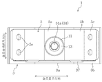
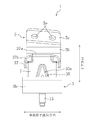
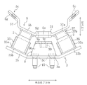
図1は、本発明に係る防振装置を示す正面図であり、図2は上面図であり、図3は側面図である。この防振装置1は、トランスミッション(変速機)25と車両のクロスメンバ(車体)27との連結部分に用いられ(図8参照)、トランスミッション25の振動がクロスメンバ27に伝わるのを緩和し、また、トルク反力や路面からの入力荷重によるトランスミッション25の移動変位を規制しつつトランスミッション25の重量を支えるようになっている。
(Embodiment 1)
-Configuration of anti-vibration device-
FIG. 1 is a front view showing a vibration isolator according to the present invention, FIG. 2 is a top view, and FIG. 3 is a side view. The
この防振装置1は、上記クロスメンバ27に取り付けられる下側取付金具3と、トランスミッション25に取り付けられる上側取付金具5と、該両取付金具3,5を一体に連結している一対の支持ゴム弾性体(インシュレータ)7,7と、該下側取付金具3に取り付けられている架台9と、該架台9に固定されているストッパボルト31と、該ストッパボルト31に取り付けられているストッパプレート13と、該上側取付金具5に一体形成されているストッパラバー11と、該下側取付金具3をクロスメンバ27に取り付けるための2本のカシメボルト(締結部材)15,15とを備えている。
The
上記下側取付金具3は、略長方形状の鋼板を折り曲げ加工した長尺物の金具である。この下側取付金具3は、上記クロスメンバ27に取り付けられる下側水平部3aと、金具長手方向(上記一対の支持ゴム弾性体7,7を結ぶ方向)における該下側水平部3aの金具長手方向両端部から金具長手方向外側に行くに従って上方に傾斜して延びている一対の下側傾斜部3b,3bとを有している。
The
上記下側水平部3aには、上下方向に延びるボルト挿通孔3c,3cが金具長手方向に2つ並設されている。これらのボルト挿通孔3c,3cには、カシメボルト15,15が挿通されている。カシメボルト15,15は、ボルト挿通孔3c,3cの孔壁部をかしめることにより下側水平部3aに取り付けられている。そして、下側取付金具3は、これらカシメボルト15,15を車両のクロスメンバ27に締結することで、車体に固定されるようになっている。また、この下側水平部3aには、上記架台9が取り付けられている。
The lower
上記各下側傾斜部3b,3bは、下側水平部3aの金具長手方向両端から略30度傾斜して斜め上方に延びている。これら各下側傾斜部3b,3bには、上下方向と金具長手方向とに直交する金具長手直角方向における防振装置1のバネ特性を高めるための下側補強部35,35がそれぞれ設けられている。
Each of the lower
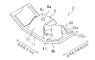
上記架台9は、鋼板を折り曲げ加工したものであり、略長方形状の頂壁部9aと、該頂壁部9aの金具長手直角方向両端部から下方に行くほど金具長手直角方向外側に傾斜して延びている略台形状の側壁部9b,9bとを有している。架台9は、各側壁部9b,9bの下端を下側水平部3aに溶接することにより、図4に示すように、金具長手方向に開口する閉断面を形成し、2つカシメボルト15,15を跨ぐように下側水平部3aに固定されている。換言すると、架台9は、金具長手方向から見て下側水平部3aを下底とする中空台形状に形成されていて、2つのカシメボルト15,15を覆うように金具長手方向に延びている。また、頂壁部9aの中央には、上記ストッパボルト31を取付固定するための上下方向に延びている取付孔9cが形成されている。さらに、頂壁部9aの下面には、この取付孔9cの周縁部を覆うようにナット39が溶接で取り付けられている。
The
このように架台9は、金具長手方向に開口する閉断面を形成し且つカシメボルト15,15を跨ぐように下側水平部3aに取り付けられているので、カシメボルト15,15の本数が増えたり、カシメボルト15,15同士の金具長手方向の間隔が拡がったりしても、カシメボルト15,15との干渉を回避することができる。したがって、カシメボルト15,15との干渉を避けるために架台9を大きくする必要がないので、防振装置1が大型化するのを抑えることができる。
As described above, the
さらに、架台9は、下側取付金具3と閉断面を形成しているとともに、その側壁部9bが金具長手方向に延びていて下側取付金具3のリブとしても機能するので、防振装置1の金具長手方向の剛性を高めることができる。
Further, the
一方、上記下側補強部35は、下側取付金具3よりも厚さの薄い鋼板を折り曲げ加工したものであり、該下側傾斜部3bの傾斜方向に延び、支持ゴム弾性体7の下端部を切り欠くように該傾斜方向から見て断面逆V字状に形成されている補強本体部35aと、該補強本体部35aの下端部から金具長手直角方向外側に延びているフランジ部35b,35bとを有している。各下側補強部35,35は、フランジ部35b,35bを各下側傾斜部3b,3bに溶接することで、下側取付金具3に取り付けられている。
On the other hand, the lower reinforcing
上記上側取付金具5は、略長方形状の鋼板を折り曲げ加工したものであり、上側水平部5aと、該上側水平部5aの金具長手方向両端部から金具長手方向外側に行くに従って上方に傾斜して延びている一対の上側傾斜部5b,5bと、これら上側傾斜部5b,5bから外側に延びていてトランスミッション25に取り付けられる一対の上側取付部5c,5cとを有していて、上記下側取付金具3と対向配置されている。
The
上記上側水平部5aは、上記架台9の頂壁部9aと上下方向に所定間隔を空けて、上記下側取付金具3の下側水平部3aの上方に対向配置されている。この上側水平部5aには、その中央に上下方向に延びる貫通孔5dが形成されている。
The upper
上記各上側傾斜部5b,5bは、上側水平部5aの金具長手方向両端から略30度傾斜して(各下側傾斜部3b,3bと平行に)斜め上方に延びており、各下側傾斜部3b,3bの斜め上方に対向配置されている。各上側傾斜部5b,5bには、防振装置1の金具長手直角方向におけるバネ特性を高めるための上側補強部37,37がそれぞれ設けられている。
Each of the upper
上記各上側取付部5c,5cは、上記各上側傾斜部5b,5bの金具長手方向の端部から上方に延びる立壁部5f,5fと、該各立壁部5f,5fの上端から略45度傾斜して斜め上方にそれぞれ延びている傾斜部5g,5gとを有している。このように、各上側取付部5c,5cに立壁部5f,5fを形成しているのは、防振装置1をトランスミッション25に取り付けた状態で、トランスミッション25と防振装置1との上下方向の間隔を確保する(上記ストッパボルト31とトランスミッション25との干渉を抑える)ためである。各傾斜部5g,5gには、該傾斜部5g,5gと直交する方向に延びるボルト挿通孔5e,5eが2つづつ形成されており、該ボルト挿通孔5e,5eに挿通されるボルト(図示せず)により、防振装置1がトランスミッション25に取り付けられるようになっている。
The
上記各上側補強部37,37は、上側取付金具5よりも厚さの薄い鋼板を折り曲げ加工したものであり、頂壁部37aと、該頂壁部37aの金具長手直角方向両端から外側に膨らむ湾曲形状をなしながら下方に延びる側壁部37b,37bを有していて、金具長手直角方向から各支持ゴム弾性体7,7の上端部を挟むように形成されている。換言すると、各上側補強部37,37は、各上側傾斜部5b,5bの傾斜方向に延び、図5に示すように、該傾斜方向から見て断面逆U字状に形成されていて、頂壁部37aと側壁部37b,37bとによって、各支持ゴム弾性体7,7の上端部を囲むようになっている。各上側補強部37,37は、各頂壁部37a,37aを各上側傾斜部5b,5bに溶接することで、上側取付金具5に取り付けられている。なお、各側壁部37b,37bは、上記下側補強部35と上下方向に重ならない範囲で下方に延びている。
Each of the upper reinforcing
上記各支持ゴム弾性体7,7は、加硫成形により上側取付金具5及び下側取付金具3と一体化されたゴム部材であり、下方に行くほど金具長手方向外側に傾斜していて、左側の上側傾斜部5bと左側の下側傾斜部3bとを、また右側の上側傾斜部5bと右側の下側傾斜部3bとをそれぞれ連結している。より詳しくは、各支持ゴム弾性体7,7は、左側の上側補強部37と左側の下側補強部35とを、また右側の上側補強部37と右側の下側補強部35とをそれぞれ連結している。換言すると、各支持ゴム弾性体7,7は、その上端が上側取付金具5の各上側補強部37,37に加硫接着されているとともに、その下端が下側取付金具3の各下側補強部35,35に加硫接着されている。各支持ゴム弾性体7,7は略30度傾いていて、上下方向と金具長手方向とのバネ特性の比が略2:1に設定されている。
Each of the supporting rubber
ここで、従来の防振装置では、上側傾斜部及び下側傾斜部の傾斜角度を調整することにより、上下方向又は金具長手方向から入力した荷重や振動を、支持ゴム弾性体に圧縮方向の荷重や振動として作用させることで、上下方向及び水平一方向において高いバネ特性が得られるようになっているが、金具長手直角方向から荷重や振動が入力した場合、支持ゴム弾性体の角度を調整しても、支持ゴム弾性体にはせん断方向の荷重や振動が作用することから、高いバネ特性を得ることが困難であった。このため、例えば、上下方向、金具長手方向(車幅方向)及び金具長手直角方向(車両前後方向)のバネ特性の比が略2:1:0.625となり、防振装置に対して車両前後方向に大きな荷重が入力された場合、車体に振動が伝わるのを押さえることが困難であった。 Here, in the conventional vibration isolator, by adjusting the inclination angle of the upper inclined portion and the lower inclined portion, the load or vibration input from the vertical direction or the metal fitting longitudinal direction is applied to the support rubber elastic body in the compression direction. By acting as a vibration, it is possible to obtain high spring characteristics in the vertical direction and horizontal one direction, but when a load or vibration is input from the direction perpendicular to the longitudinal direction of the bracket, the angle of the support rubber elastic body is adjusted. However, since the load and vibration in the shear direction act on the support rubber elastic body, it is difficult to obtain high spring characteristics. For this reason, for example, the ratio of spring characteristics in the vertical direction, the longitudinal direction of the bracket (vehicle width direction), and the direction perpendicular to the longitudinal direction of the bracket (vehicle longitudinal direction) is approximately 2: 1: 0.625, which is When a large load is input in the direction, it is difficult to suppress the transmission of vibration to the vehicle body.
これに対し、本実施形態の支持ゴム弾性体7,7は、上述のように、その上端部が上側補強部37,37によって金具長手直角方向から挟まれているとともに、その下端部が下側補強部35,35によって金具長手直角方向への移動が規制されているので、金具長手直角方向から荷重や振動が入力した場合、支持ゴム弾性体7,7には圧縮方向の荷重や振動が作用することから、所望の高いバネ特性が得られるようになっている。
On the other hand, as described above, the support rubber
また、支持ゴム弾性体7,7は、下側補強部35,35によって下端部が切り欠かれているが、上側補強部37,37を断面逆U字状に形成することで、支持ゴム弾性体7,7における金具長手直角方向中央部のラバーボリューム(ゴム弾性体の体積)が確保されているので、その上下方向や金具長手方向におけるバネ特性の低下が抑えられている。したがって、本実施形態の防振装置1によれば、例えば、上下方向、車幅方向及び車両前後方向のバネ特性の比を略2:1:1に設定することが可能となる。なお、上下方向又は金具長手方向における防振装置1のバネ特性は、上側傾斜部5b及び下側傾斜部3bの傾斜角度を調整することにより設定されるのに対し、金具長手直角方向における防振装置1のバネ特性は、例えば、断面逆V字状に形成されている補強本体部35aの開き角度を調整することにより設定される。
Further, the lower end portions of the supporting rubber
上記ストッパラバー11は、環状をなしていて、図6に示すように、貫通孔5dの内周面及び周縁部を覆うように上側水平部5aに一体形成されている。なお、ストッパラバー11は、成形用金型に形成された1つの注入孔でゴム部材を成形するために、上記各支持ゴム弾性体7,7と連結されている。
The
上記ストッパボルト31は、環状のストッパラバー11とその径方向に間隔を空けて該ストッパラバー11(貫通孔5d)を貫通している。このストッパボルト31は、その下端部が上記架台9の頂壁部9aに形成されている取付孔9cに挿通されていて上記ナット39で固定されている。
The
上記ストッパプレート13は、環状に形成されており、上側水平部5aよりも上側でストッパボルト31に取り付けられていて、その外径が上側水平部5aの貫通孔5dよりも大径となっている。より詳しくは、ストッパプレート13は、ストッパボルト31を囲むように架台9の頂壁部9aに載置されている筒状のスペーサー33の上端に載置されていることで、上記ストッパラバー11の上方に位置しており、該スペーサー33の上端とストッパボルト31の頭部31aとに挟まれている。このスペーサー33は、環状のストッパラバー11とその径方向に所定間隔を空けて該ストッパラバー11を貫通している。なお、径方向に所定間隔を空けて環状のストッパラバー11を貫通し、ストッパプレート13が取り付けられているとともに架台9の上端部に固定されている、本発明で言うところのストッパピンは、ストッパボルト31及びスペーサー33に対応する。
The
−防振装置の組立手順−
次に、防振装置1の組立手順について説明する。
-Assembly procedure of vibration isolator-
Next, the assembly procedure of the
先ず、上記下側取付金具3の下側水平部3aに形成されているボルト挿通孔3c,3cに上記カシメボルト15,15を挿通し、カシメボルト15,15を下側水平部3aに取付固定する。次いで、上記ナット39が溶接された上記架台9をカシメボルト15,15を跨ぐように下側取付金具3の下側水平部3aに配置し、該架台9の各側壁部9b,9bの下端を該下側水平部3aに溶接することにより、架台9を下側取付金具3に取り付ける。また、下側取付金具3の各下側傾斜部3b,3bにフランジ部35b,35bを溶接することで、下側補強部35,35を下側取付金具3に取り付ける。
First, the
一方、上側取付金具5の各上側傾斜部5b,5bには、該各上側傾斜部5b,5bの傾斜方向から見て断面逆U字状をなすように上側補強部37,37を配置し、頂壁部37a,37aを上側傾斜部5b,5bに溶接することで、上側補強部37,37を上側取付金具5に取り付ける。
On the other hand, the upper reinforcing
そして、下側取付金具3の金具長手直角方向と同じ方向に開閉する成形用金型を用意し、上側取付金具5の上側水平部5aが、架台9の頂壁部9aと所定間隔を空けて下側取付金具3の下側水平部3aと対向し、上側取付金具5の一対の上側傾斜部5b,5bが、下側取付金具3の一対の下側傾斜部3b,3bと対向するような位置関係で、両取付金具3,5を該成形用金型内にセットする。
Then, a molding die that opens and closes in the same direction as the bracket longitudinal direction of the
次いで、未加硫ゴム組成物を射出して、それを図示しないゴム注入孔を介して成形用金型内のキャビティに充填する。そして、型締めを行い、所定温度で所定時間そのままの状態を保持する。このとき、ゴムが加硫して一対の支持ゴム弾性体7,7及びストッパラバー11が成形されるとともに、これらゴム部材が下側補強部35,35や上側補強部37,37や上側水平部5aに加硫接着されて一体化する。
Next, an unvulcanized rubber composition is injected and filled into a cavity in a molding die through a rubber injection hole (not shown). Then, mold clamping is performed, and the state is maintained at a predetermined temperature for a predetermined time. At this time, the rubber is vulcanized to form a pair of support rubber
その後、成形用金型を開き、図7に示すように、下側取付金具3と上側取付金具5と一対の支持ゴム弾性体7,7とストッパラバー11とが一体に加硫成形された半製品を取り出す。
Thereafter, the molding die is opened, and as shown in FIG. 7, the
次いで、上記スペーサー33を上側水平部5aの貫通孔5dに挿通し、該スペーサー33の下端を架台9に形成された取付孔9cの周縁部に当接させる。そして、ストッパプレート13をスペーサー33の上端に載置した状態で、上記ストッパボルト31を上方からストッパプレート13及びスペーサー33に挿通し、その下端部をナット39で締め付けることで、ストッパボルト31及びスペーサー33(ストッパピン)とストッパプレート13とを架台9に固定する。
Next, the
−防振装置の車体及び変速機への取付状態−
図8は、防振装置のトランスミッションへの取付状態を模式的に示す側面図である。図8中の符合23は、エンジンを示し、符合25は、マニュアルトランスミッションを示し、符合27は、車両のクロスメンバを示す。この車両は四輪駆動車であり、エンジン23が縦置きに搭載されている。また、クロスメンバ27は、マニュアルトランスミッション25の後端部を横切るように車幅方向に延びている。
-Mounting state of the vibration isolator to the vehicle body and transmission-
FIG. 8 is a side view schematically showing an attachment state of the vibration isolator to the transmission.
マニュアルトランスミッション25は、その配置、重量、支持点数、出力等との関係上、上下方向及び車幅方向に大きな荷重が入力されるようになっている。このため、防振装置1は、上記金具長手方向が車幅方向と略一致するように、クロスメンバ27及びマニュアルトランスミッション25に取り付けられている。
The
具体的には、防振装置1は、下側取付金具3の下側水平部3aをクロスメンバ27の上面に載置し、該下側水平部3aのボルト挿通孔3c,3cに挿通されているカシメボルト15,15を、クロスメンバ27に形成されているボルト挿通孔27a,27aに挿通して図示しないナットで締め付けることにより、クロスメンバ27に締結されている。
Specifically, in the
一方、防振装置1は、上側取付金具5の傾斜部5g,5gをマニュアルトランスミッション25に当接させた状態で、該傾斜部5g,5gに形成されたボルト挿通孔5e,5eに挿通されたボルトをマニュアルトランスミッション25に設けられたナット(図示せず)で締め付けることで、該マニュアルトランスミッション25に取り付けられている。
On the other hand, the
−防振装置の動作−
次に、防振装置1の作用について説明する。
-Operation of vibration isolator-
Next, the operation of the
例えば、エンジン23始動後のようにマニュアルトランスミッション25から入力される振動や荷重が小さい場合には、上記各支持ゴム弾性体7,7が主として上下方向及び車幅方向の振動を吸収して減衰させて、振動が車体に伝わるのを緩和する。
For example, when the vibration and load input from the
これに対し、例えば悪路走行時等において、防振装置1に対し下向きに大きな荷重が作用すると、支持ゴム弾性体7,7が下方に変形し、それに伴って上記上側取付金具5が下方に変位する。そして、上側水平部5aに形成された貫通孔5dの周縁部を覆うストッパラバー11が架台9の頂壁部9aに当接することで、支持ゴム弾性体7,7の下方への過度の変形が抑えられる。一方、上方へのリバウンド時には、ストッパラバー11がストッパプレート13の下面に当接するので、支持ゴム弾性体7,7の上方への過大な変位を抑えられる。
On the other hand, for example, when traveling on a rough road, if a large downward load is applied to the
また、例えば車両が急停車したときや急発進したときのように、マニュアルトランスミッション25の慣性力により、防振装置1に対し車両前後方向に大きな荷重が作用すると、下側補強部35,35及び上側補強部37,37によりバネ特性が高められた支持ゴム弾性体7,7が荷重を吸収するとともに車両前後方向(金具長手直角方向)に変形し、それに伴って上側取付金具5が車両前後方向に変位する。そして、貫通孔5dの内周面を覆うストッパラバー11がスペーサー33(ストッパピン)に当接し、支持ゴム弾性体7,7の車両前後方向への過度の変形が抑えられる。
Further, when a large load is applied to the
さらに、マニュアルトランスミッション25が車体に対しローリング方向に大きく振動して防振装置1に対し車幅方向(金具長手方向)に荷重が入力したときには、上側取付金具5が車幅方向に変位して貫通孔5dの内周面を覆うストッパラバー11がスペーサー33に当接し、支持ゴム弾性体7,7の車幅方向への変形が抑えられる。
Further, when the
−効果−
本実施形態によれば、各支持ゴム弾性体7,7は、上側取付金具5の各上側傾斜部5b,5bと下側取付金具3の各下側傾斜部3b,3bとをそれぞれ連結しているので、各傾斜部3b,3b,5b,5bの角度を調整して各支持ゴム弾性体7,7に圧縮方向の荷重を作用させることで、上下方向及び金具長手方向における防振装置1のバネ特性を高く設定することができる。
-Effect-
According to the present embodiment, the support rubber
また、各下側傾斜部3b,3bには、該各下側傾斜部3b,3bの傾斜方向に延び、各支持ゴム弾性体7,7の下端部を切り欠くように該傾斜方向から見て断面逆V字状に形成されている下側補強部35,35が設けられている一方、各上側傾斜部5b,5bには、金具長手直角方向から各支持ゴム弾性体7,7を挟むように形成されている上側補強部37,37が設けられているので、簡単な構造でせん断方向の荷重を圧縮方向の荷重として各支持ゴム弾性体7,7に作用させ、金具長手直角方向における防振装置1のバネ特性を高く設定することができる。
Further, the lower
さらに、上側取付金具5の貫通孔5dをストッパボルト31及びスペーサー33が貫通しており、且つ上側取付金具5がストッパプレート13と架台9によって上下方向に挟まれているので、万が一支持ゴム弾性体7,7が破断した場合にも、マニュアルトランスミッション25が大きく傾いて脱落するのを抑制することができる。
Furthermore, since the
したがって、製造工程及び部品点数の増大を抑えつつ三方向でそれぞれ所望のバネ特性を得るとともに、マニュアルトランスミッション25の脱落を確実に抑えてフェールセーフを達成することができる。
Accordingly, desired spring characteristics can be obtained in each of the three directions while suppressing an increase in the number of manufacturing steps and the number of parts, and fail-safe can be achieved by reliably preventing the
また、各上側補強部37,37は、傾斜方向から見て断面逆U字状に形成されているので、金具長手直角方向から各支持ゴム弾性体7,7を挟むことができる。したがって、簡単な構造で、金具長手直角方向における防振装置1のバネ特性を高く設定することができる。
Moreover, since each upper
さらに、下側及び上側取付金具3,5は、金具長手方向が車幅方向と略一致するようにクロスメンバ27及びマニュアルトランスミッション25に取り付けられているので、例えば、マニュアルトランスミッション25が車体に対しローリング方向に大きく振動して車幅方向に大きな荷重が入力した場合にも、マニュアルトランスミッション25とクロスメンバ27との相対振動を支持ゴム弾性体7,7によって吸収することができる。
Furthermore, since the lower and upper mounting
また、各支持ゴム弾性体7,7は、下側及び上側補強部35,35,37,37により金具長手直角方向(車両前後方向)のバネ特性が高く設定されているので、例えば、車両が急停車したときや急発進したときのように、マニュアルトランスミッション25の慣性力により車両前後方向に大きな荷重が入力した場合にも、マニュアルトランスミッション25とクロスメンバ27との相対振動を支持ゴム弾性体7,7によって吸収することができる。
In addition, since each of the supporting rubber
(実施形態2)
本実施形態は、各上側補強部47,47の形状が実施形態1と異なるものである。以下、実施形態1と異なる点について説明する。
(Embodiment 2)
In the present embodiment, the shapes of the upper reinforcing
図9は、金具長手方向一側の上側及び下側補強部並びに支持ゴム弾性体を示す図である。以下、金具長手方向一側の上側補強部47について説明するが、金具長手方向他側の上側補強部47の構成も該一側の上側補強部47と同様である。なお、図9では、架台9やストッパラバー11等は図示省略している。
FIG. 9 is a diagram showing the upper and lower reinforcing portions on one side of the metal fitting longitudinal direction and the supporting rubber elastic body. Hereinafter, the upper reinforcing
上側補強部47は、略矩形状のフラット鋼板をプレス加工したものであり、金具長手直角方向両端における中央部が下側傾斜部に向かって膨出することにより、金具長手直角方向両端部が金具長手直角方向から見て断面逆ハット状に形成されているとともに、傾斜方向中央部が傾斜方向から見て断面略ハット状に形成されている。
The upper reinforcing
より詳しくは、上側補強部47の金具長手直角方向両端部には、金具長手直角方向から見て断面逆ハット状に形成されている膨出部47a,47aが形成されている。各膨出部47a,47aは、フラット鋼板の金具長手直角方向両端部における中央部を斜め下方(上側傾斜部5bから下側傾斜部3bへ向かう方向)へ膨出させることで、上側傾斜部5bと略平行に形成された底壁部47bと、中央部の膨出に伴って形成され、該底壁部47bの傾斜方向両端部から上方に末広がりに傾斜して延びている第1傾斜部47c,47cと、フラット形状を維持していて、該第1傾斜部47c,47cの上端部から傾斜方向外側に延びている第1頂壁部47e,47eと、下側水平部47bの金具長手直角方向内側の端部から上方に行くに従って金具長手直角方向内側に傾斜して延びている第2傾斜部47dとを有している。第2傾斜部47d,47dは、第1傾斜部47c,47cの金具長手直角方向内側の端部と繋がっており、図9(a)に示すように、各膨出部47a,47aの妻壁を構成している。
More specifically, bulging
このように、上側補強部47の金具長手直角方向両端部に、膨出部47a,47aが形成されていることにより、傾斜方向中央部は、図9(b)に示すように、傾斜方向から見て、フラット形状を維持している第2頂壁部47fと、第2傾斜部47d,47dと、底壁部47b,47bとからなる断面略ハット状に形成されている。
In this way, the bulging
第1頂壁部47e,47eは金具長手直角方向に延びている一方、第2頂壁部47fは傾斜方向に延びており、これら第1及び第2頂壁部47e,47e,47fが、フラットで且つH字状をなす頂壁部を形成している。そして、上側補強部47は、上側傾斜部5bの下面に頂壁部47e,47e,47fを溶接することにより、上側傾斜部5bに取り付けられている。
The first
これにより、一方側の支持ゴム弾性体の上端部が、金具長手直角方向両端部に形成された膨出部47a,47aによって、金具長手直角方向両側から挟まれることになる。
As a result, the upper end portion of the support rubber elastic body on one side is sandwiched from the both sides of the bracket longitudinal direction by the bulging
また、下側水平部47b、第1傾斜部47c,47c及び上側水平部47e,47eの端部(エッジ)は、金具長手直角方向外側を向いているので、支持ゴム弾性体7を加硫成形する際には、金具長手直角方向と同じ方向に開閉する成形用金型を用意し、該成形用金型に膨出部47aと同じ逆ハット状の溝を形成し、該溝に膨出部47aのエッジを差し込むことで、シール性を容易に確保することができる。
Further, since the end portions (edges) of the lower
−効果−
本実施形態によれば、金具長手直角方向の両端部膨出することで、上側傾斜部5bの傾斜方向から見て断面略ハット状に形成されているので、金具長手直角方向から各支持ゴム弾性体7,7を挟むことができる。したがって、簡単な構造で、防振装置1の金具長手直角方向のバネ特性を高く設定することができる。
-Effect-
According to the present embodiment, both end portions in the direction perpendicular to the longitudinal direction of the metal fitting bulge out so that the cross section is substantially hat-shaped when viewed from the inclination direction of the upper
さらに、各上側補強部35,35は、金具長手直角方向及び傾斜方向の2方向で屈曲する形状に形成されているので、その耐久性を向上させることができる。
Furthermore, since each upper
(実施形態3)
本実施形態は、各上側補強部57,57が実施形態1及び2と異なるものである。以下、実施形態1及び2と異なる点について説明する。
(Embodiment 3)
In the present embodiment, the upper reinforcing
図10は、金具長手方向一側の上側及び下側補強部並びに支持ゴム弾性体を示す図である。以下、金具長手方向一側の上側補強部57について説明するが、金具長手方向他側の上側補強部57の構成も該一側の上側補強部57と同様である。なお、図10では、架台9やストッパラバー11等は図示省略している。
FIG. 10 is a diagram showing the upper and lower reinforcing portions on one side of the metal fitting longitudinal direction and the supporting rubber elastic body. Hereinafter, the upper reinforcing
上側補強部57は、上側傾斜部5bをプレス加工することにより、上記実施形態2の上側補強部47とほぼ同様の形状に形成されている。
The upper reinforcing
より詳しくは、上側補強部57の金具長手直角方向両端部には、金具長手直角方向から見て断面逆ハット状に形成されている膨出部57a,57aが形成されている。各膨出部57a,57aは、上側傾斜部5bの金具長手直角方向両端部における中央部を斜め下方(上側傾斜部5bから下側傾斜部3bへ向かう方向)へ膨出させることで形成された底壁部57bと、中央部の膨出に伴って形成された第1傾斜部57c,57cと、フラット形状を維持している第1頂壁部57e,57eと、各膨出部57a,57aの妻壁を構成している第2傾斜部57dとを有している。
More specifically, bulging
このように、上側補強部57の金具長手直角方向両端部に、膨出部57a,57aが形成されていることにより、傾斜方向中央部は、図10(b)に示すように、傾斜方向から見て、フラット形状を維持している第2頂壁部57fと、第2傾斜部57d,57dと、底壁部57b,57bとからなる断面略ハット状に形成されている。
In this way, the bulging
−効果−
本実施形態によれば、製造工程及び部品点数を減らしつつ、上記実施形態2と同様の効果を得ることができる。
-Effect-
According to the present embodiment, it is possible to obtain the same effects as those of the second embodiment while reducing the manufacturing process and the number of parts.
(その他の実施形態)
上記各実施形態では、長手方向と車幅方向とが略一致するように、防振装置1をクロスメンバ27及びトランスミッション25に取り付けたが、これに限らず、例えば、車幅方向よりも車両前後方向の振動が大きくなるように設定配置されたトランスミッション25を防振支持する場合には、長手直角方向と車幅方向とが略一致するように、防振装置1をクロスメンバ27及びトランスミッション25に取り付けてもよい。
(Other embodiments)
In each of the above embodiments, the
さらに、上記実施形態1では、防振装置1をマニュアルトランスミッション25にボルト締結したが、これに限らず、例えば、オートマチックトランスミッションにボルト締結してもよい。
Further, in the first embodiment, the
また、上記各実施形態では、防振装置1をクロスメンバ27に取り付けたが、これに限らず、他の車体フレーム部材に防振装置1を取り付けてもよい。
Moreover, in each said embodiment, although the
さらに、上記各実施形態では、ストッパボルト31とスペーサー33とによりストッパピンを構成したが、これに限らず、例えば、十分な強度を有し、ストッパプレート13と一体に形成される大径のストッパボルト31を用いるのであれば、スペーサー33を用いなくてもよい。
Furthermore, in each said embodiment, although the stopper pin was comprised by the
本発明は、実施形態に限定されず、その精神又は主要な特徴から逸脱することなく他の色々な形で実施することができる。 The present invention is not limited to the embodiments, and can be implemented in various other forms without departing from the spirit or main features thereof.
このように、上述の実施形態はあらゆる点で単なる例示に過ぎず、限定的に解釈してはならない。さらに、特許請求の範囲の均等範囲に属する変形や変更は、全て本発明の範囲内のものである。 As described above, the above-described embodiment is merely an example in all respects and should not be interpreted in a limited manner. Further, all modifications and changes belonging to the equivalent scope of the claims are within the scope of the present invention.
以上説明したように、本発明は、変速機を車体に対して防振支持させる防振装置等について有用である。 As described above, the present invention is useful for an anti-vibration device or the like that supports an anti-vibration of a transmission with respect to a vehicle body.
1 防振装置
3 下側取付金具
3a 下側水平部
3b 下側傾斜部
5 上側取付金具
5a 上側水平部
5b 上側傾斜部
5c 上側取付部
5d 貫通孔
7 支持ゴム弾性体
9 架台
11 ストッパラバー
13 ストッパプレート
27 クロスメンバ(車体)
25 トランスミッション(変速機)
31 ストッパボルト(ストッパピン)
33 スペーサー(ストッパピン)
35 下側補強部
37 上側補強部
DESCRIPTION OF
25 Transmission (Transmission)
31 Stopper bolt (stopper pin)
33 Spacer (Stopper pin)
35
Claims (5)
中央に上下方向に延びる貫通孔が形成されている上側水平部と、該上側水平部の金具長手方向両端部から金具長手方向外側に行くに従って上方に傾斜して延びている一対の上側傾斜部と、該上側傾斜部の金具長手方向両端部から金具長手方向外側に延びていて変速機に取り付けられる上側取付部とを有し、上記下側取付金具と対向配置されている上側取付金具と、
上記各上側傾斜部と上記各下側傾斜部とをそれぞれ連結している一対の支持ゴム弾性体と、
上記貫通孔の内周面及び周縁部を覆うように上記上側水平部に形成されている環状のストッパラバーと、
上記環状のストッパラバーとその径方向に所定間隔を空けて該ストッパラバーを貫通しているストッパピンと、
上記上側水平部の上方で上記ストッパピンに取り付けられているストッパプレートと、
上記ストッパピンの下端部が固定され、上記下側水平部に取り付けられている架台とを備えており、
上記各下側傾斜部には、該各下側傾斜部の傾斜方向に延び、上記各支持ゴム弾性体の下端部を切り欠くように該傾斜方向から見て断面略逆V字状に形成されている補強本体部を有する下側補強部がそれぞれ設けられている一方、上記各上側傾斜部には、上下方向と金具長手方向とに直交する金具長手直角方向から上記各支持ゴム弾性体の上端部を挟むように形成されている上側補強部がそれぞれ設けられていることを特徴とする防振装置。 A pair of lower parts, which is a long metal fitting, extending downwardly from the lower horizontal part of the lower horizontal part and extending from both ends of the lower metal part in the longitudinal direction to the outer side in the longitudinal direction of the metal part. A lower mounting bracket having an inclined portion;
An upper horizontal portion in which a through-hole extending in the vertical direction is formed at the center, and a pair of upper inclined portions extending obliquely upward from the both ends in the longitudinal direction of the metal fitting to the outside in the metal longitudinal direction An upper mounting part that extends from both ends of the upper inclined part in the longitudinal direction of the bracket and is attached to the transmission, and that is disposed opposite to the lower mounting bracket.
A pair of support rubber elastic bodies respectively connecting the upper inclined portions and the lower inclined portions;
An annular stopper rubber formed on the upper horizontal part so as to cover the inner peripheral surface and the peripheral part of the through hole;
The annular stopper rubber and a stopper pin penetrating the stopper rubber at a predetermined interval in the radial direction;
A stopper plate attached to the stopper pin above the upper horizontal portion;
A lower end of the stopper pin is fixed, and includes a base attached to the lower horizontal part,
Each of the lower inclined portions is formed in a substantially inverted V-shaped cross section when viewed from the inclined direction so as to extend in the inclination direction of each lower inclined portion and cut out the lower end portion of each of the supporting rubber elastic bodies. A lower reinforcing portion having a reinforcing main body portion is provided, and each upper inclined portion is provided with an upper end of each supporting rubber elastic body from the vertical direction of the bracket perpendicular to the vertical direction and the longitudinal direction of the bracket. An anti-vibration device comprising upper reinforcing portions formed so as to sandwich the portion.
上記各上側補強部は、上記傾斜方向から見て断面略逆U字状に形成され、該傾斜方向に延びていることを特徴とする防振装置。 The vibration isolator according to claim 1, wherein
Each said upper reinforcement part is formed in the cross-sectional substantially reverse U shape seeing from the said inclination direction, The vibration isolator characterized by extending in this inclination direction.
上記各上側補強部は、金具長手直角方向両端部における中央部が上記各下側傾斜部に向かって膨出していることにより、金具長手直角方向両端部が金具長手直角方向から見て断面略逆ハット状に形成されているとともに上記傾斜方向中央部が傾斜方向から見て断面略ハット状に形成されていることを特徴とする防振装置。 The vibration isolator according to claim 1, wherein
Each of the upper reinforcing portions has a substantially opposite cross section when viewed from the direction perpendicular to the longitudinal direction of the bracket, since the central portion of both ends in the direction perpendicular to the longitudinal direction of the bracket bulges toward the lower inclined portion. An anti-vibration device characterized by being formed in a hat shape and having a central section in the inclined direction as viewed in the inclined direction.
上記各上側補強部は、上記各上側傾斜部を折り曲げ加工することにより形成されていることを特徴とする防振装置。 The vibration isolator according to claim 3,
Each said upper reinforcement part is formed by bending each said upper inclination part, The vibration isolator characterized by the above-mentioned.
上記下側及び上側取付金具は、金具長手方向が車幅方向と略一致するように、車体及び変速機にそれぞれ取り付けられることを特徴とする防振装置。 In the vibration isolator as described in any one of Claims 1-4,
The anti-vibration device according to claim 1, wherein the lower and upper mounting brackets are mounted on the vehicle body and the transmission, respectively, such that the longitudinal direction of the bracket substantially coincides with the vehicle width direction.
Priority Applications (1)
| Application Number | Priority Date | Filing Date | Title |
|---|---|---|---|
| JP2008251538A JP5004361B2 (en) | 2008-09-29 | 2008-09-29 | Vibration isolator |
Applications Claiming Priority (1)
| Application Number | Priority Date | Filing Date | Title |
|---|---|---|---|
| JP2008251538A JP5004361B2 (en) | 2008-09-29 | 2008-09-29 | Vibration isolator |
Publications (2)
| Publication Number | Publication Date |
|---|---|
| JP2010084792A true JP2010084792A (en) | 2010-04-15 |
| JP5004361B2 JP5004361B2 (en) | 2012-08-22 |
Family
ID=42248962
Family Applications (1)
| Application Number | Title | Priority Date | Filing Date |
|---|---|---|---|
| JP2008251538A Active JP5004361B2 (en) | 2008-09-29 | 2008-09-29 | Vibration isolator |
Country Status (1)
| Country | Link |
|---|---|
| JP (1) | JP5004361B2 (en) |
Cited By (2)
| Publication number | Priority date | Publication date | Assignee | Title |
|---|---|---|---|---|
| JP2013253619A (en) * | 2012-06-05 | 2013-12-19 | Toyo Tire & Rubber Co Ltd | Damper |
| CN104553726A (en) * | 2015-02-02 | 2015-04-29 | 重庆凯特动力科技有限公司 | Engine assembly with suspension |
Citations (5)
| Publication number | Priority date | Publication date | Assignee | Title |
|---|---|---|---|---|
| JPS54118591U (en) * | 1978-02-07 | 1979-08-20 | ||
| JPH0439346U (en) * | 1990-07-26 | 1992-04-03 | ||
| JPH09151991A (en) * | 1995-11-28 | 1997-06-10 | Tokai Rubber Ind Ltd | Anti-vibration support device for vehicle |
| JP2004003597A (en) * | 2002-03-26 | 2004-01-08 | Tokai Rubber Ind Ltd | Anti-vibration support device |
| JP2006273156A (en) * | 2005-03-29 | 2006-10-12 | Tokai Rubber Ind Ltd | Anti-vibration support structure for engine mount and power unit using the same |
-
2008
- 2008-09-29 JP JP2008251538A patent/JP5004361B2/en active Active
Patent Citations (5)
| Publication number | Priority date | Publication date | Assignee | Title |
|---|---|---|---|---|
| JPS54118591U (en) * | 1978-02-07 | 1979-08-20 | ||
| JPH0439346U (en) * | 1990-07-26 | 1992-04-03 | ||
| JPH09151991A (en) * | 1995-11-28 | 1997-06-10 | Tokai Rubber Ind Ltd | Anti-vibration support device for vehicle |
| JP2004003597A (en) * | 2002-03-26 | 2004-01-08 | Tokai Rubber Ind Ltd | Anti-vibration support device |
| JP2006273156A (en) * | 2005-03-29 | 2006-10-12 | Tokai Rubber Ind Ltd | Anti-vibration support structure for engine mount and power unit using the same |
Cited By (2)
| Publication number | Priority date | Publication date | Assignee | Title |
|---|---|---|---|---|
| JP2013253619A (en) * | 2012-06-05 | 2013-12-19 | Toyo Tire & Rubber Co Ltd | Damper |
| CN104553726A (en) * | 2015-02-02 | 2015-04-29 | 重庆凯特动力科技有限公司 | Engine assembly with suspension |
Also Published As
| Publication number | Publication date |
|---|---|
| JP5004361B2 (en) | 2012-08-22 |
Similar Documents
| Publication | Publication Date | Title |
|---|---|---|
| JP7444225B2 (en) | Vehicle side structure | |
| JP4865637B2 (en) | Cylindrical vibration isolator | |
| US8801072B2 (en) | Vehicular fastening structure | |
| JP2010100275A (en) | Sub-frame for suspension | |
| US9382961B2 (en) | Vibration damping device | |
| JP2010084791A (en) | Vibration isolating device | |
| US10814915B2 (en) | Vehicle center pillar | |
| JP2015096754A (en) | Vibration-proof device | |
| JP2012006537A (en) | Cowl box | |
| US10661648B2 (en) | Rubber stopper | |
| JP5646213B2 (en) | Vibration isolator | |
| JP2012116242A (en) | Engine mount of vehicle | |
| JP5186138B2 (en) | Anti-vibration rubber stopper for railway vehicles | |
| JP5004361B2 (en) | Vibration isolator | |
| JP3627406B2 (en) | Cylindrical anti-vibration support | |
| WO2012001906A1 (en) | Anti-vibration device | |
| JP5172566B2 (en) | Vibration isolator | |
| US12246772B2 (en) | Automobile suspension structure | |
| JP7148664B1 (en) | Vehicle side door structure | |
| JP3226546U (en) | Body up mount and vehicle using it | |
| JP6393443B2 (en) | Vibration isolator bracket and vibration isolator using the same | |
| JP2019210946A (en) | Dynamic damper | |
| JP2014133520A (en) | Vehicle body front part structure | |
| JP2023150837A (en) | Vehicle side structure | |
| JP4523374B2 (en) | Suspension link |
Legal Events
| Date | Code | Title | Description |
|---|---|---|---|
| A621 | Written request for application examination |
Free format text: JAPANESE INTERMEDIATE CODE: A621 Effective date: 20110805 |
|
| A977 | Report on retrieval |
Free format text: JAPANESE INTERMEDIATE CODE: A971007 Effective date: 20120406 |
|
| TRDD | Decision of grant or rejection written | ||
| A01 | Written decision to grant a patent or to grant a registration (utility model) |
Free format text: JAPANESE INTERMEDIATE CODE: A01 Effective date: 20120424 |
|
| A01 | Written decision to grant a patent or to grant a registration (utility model) |
Free format text: JAPANESE INTERMEDIATE CODE: A01 |
|
| A61 | First payment of annual fees (during grant procedure) |
Free format text: JAPANESE INTERMEDIATE CODE: A61 Effective date: 20120521 |
|
| FPAY | Renewal fee payment (event date is renewal date of database) |
Free format text: PAYMENT UNTIL: 20150601 Year of fee payment: 3 |
|
| R150 | Certificate of patent or registration of utility model |
Free format text: JAPANESE INTERMEDIATE CODE: R150 Ref document number: 5004361 Country of ref document: JP Free format text: JAPANESE INTERMEDIATE CODE: R150 |
|
| R250 | Receipt of annual fees |
Free format text: JAPANESE INTERMEDIATE CODE: R250 |
|
| R250 | Receipt of annual fees |
Free format text: JAPANESE INTERMEDIATE CODE: R250 |
|
| R250 | Receipt of annual fees |
Free format text: JAPANESE INTERMEDIATE CODE: R250 |
|
| R250 | Receipt of annual fees |
Free format text: JAPANESE INTERMEDIATE CODE: R250 |
|
| R250 | Receipt of annual fees |
Free format text: JAPANESE INTERMEDIATE CODE: R250 |
|
| R250 | Receipt of annual fees |
Free format text: JAPANESE INTERMEDIATE CODE: R250 |
|
| R250 | Receipt of annual fees |
Free format text: JAPANESE INTERMEDIATE CODE: R250 |
|
| R250 | Receipt of annual fees |
Free format text: JAPANESE INTERMEDIATE CODE: R250 |
|
| R250 | Receipt of annual fees |
Free format text: JAPANESE INTERMEDIATE CODE: R250 |
|
| R250 | Receipt of annual fees |
Free format text: JAPANESE INTERMEDIATE CODE: R250 |
|
| R250 | Receipt of annual fees |
Free format text: JAPANESE INTERMEDIATE CODE: R250 |