JP2010141337A - Mobile power supply device - Google Patents
Mobile power supply device Download PDFInfo
- Publication number
- JP2010141337A JP2010141337A JP2009280885A JP2009280885A JP2010141337A JP 2010141337 A JP2010141337 A JP 2010141337A JP 2009280885 A JP2009280885 A JP 2009280885A JP 2009280885 A JP2009280885 A JP 2009280885A JP 2010141337 A JP2010141337 A JP 2010141337A
- Authority
- JP
- Japan
- Prior art keywords
- housing
- light
- power supply
- portable power
- supply device
- Prior art date
- Legal status (The legal status is an assumption and is not a legal conclusion. Google has not performed a legal analysis and makes no representation as to the accuracy of the status listed.)
- Pending
Links
Images


Classifications
-
- H—ELECTRICITY
- H02—GENERATION; CONVERSION OR DISTRIBUTION OF ELECTRIC POWER
- H02S—GENERATION OF ELECTRIC POWER BY CONVERSION OF INFRARED RADIATION, VISIBLE LIGHT OR ULTRAVIOLET LIGHT, e.g. USING PHOTOVOLTAIC [PV] MODULES
- H02S40/00—Components or accessories in combination with PV modules, not provided for in groups H02S10/00 - H02S30/00
- H02S40/30—Electrical components
- H02S40/38—Energy storage means, e.g. batteries, structurally associated with PV modules
-
- H—ELECTRICITY
- H10—SEMICONDUCTOR DEVICES; ELECTRIC SOLID-STATE DEVICES NOT OTHERWISE PROVIDED FOR
- H10F—INORGANIC SEMICONDUCTOR DEVICES SENSITIVE TO INFRARED RADIATION, LIGHT, ELECTROMAGNETIC RADIATION OF SHORTER WAVELENGTH OR CORPUSCULAR RADIATION
- H10F77/00—Constructional details of devices covered by this subclass
- H10F77/40—Optical elements or arrangements
- H10F77/42—Optical elements or arrangements directly associated or integrated with photovoltaic cells, e.g. light-reflecting means or light-concentrating means
- H10F77/488—Reflecting light-concentrating means, e.g. parabolic mirrors or concentrators using total internal reflection
-
- H—ELECTRICITY
- H02—GENERATION; CONVERSION OR DISTRIBUTION OF ELECTRIC POWER
- H02S—GENERATION OF ELECTRIC POWER BY CONVERSION OF INFRARED RADIATION, VISIBLE LIGHT OR ULTRAVIOLET LIGHT, e.g. USING PHOTOVOLTAIC [PV] MODULES
- H02S10/00—PV power plants; Combinations of PV energy systems with other systems for the generation of electric power
-
- H—ELECTRICITY
- H02—GENERATION; CONVERSION OR DISTRIBUTION OF ELECTRIC POWER
- H02S—GENERATION OF ELECTRIC POWER BY CONVERSION OF INFRARED RADIATION, VISIBLE LIGHT OR ULTRAVIOLET LIGHT, e.g. USING PHOTOVOLTAIC [PV] MODULES
- H02S10/00—PV power plants; Combinations of PV energy systems with other systems for the generation of electric power
- H02S10/40—Mobile PV generator systems
-
- H—ELECTRICITY
- H02—GENERATION; CONVERSION OR DISTRIBUTION OF ELECTRIC POWER
- H02S—GENERATION OF ELECTRIC POWER BY CONVERSION OF INFRARED RADIATION, VISIBLE LIGHT OR ULTRAVIOLET LIGHT, e.g. USING PHOTOVOLTAIC [PV] MODULES
- H02S40/00—Components or accessories in combination with PV modules, not provided for in groups H02S10/00 - H02S30/00
- H02S40/20—Optical components
- H02S40/22—Light-reflecting or light-concentrating means
-
- Y—GENERAL TAGGING OF NEW TECHNOLOGICAL DEVELOPMENTS; GENERAL TAGGING OF CROSS-SECTIONAL TECHNOLOGIES SPANNING OVER SEVERAL SECTIONS OF THE IPC; TECHNICAL SUBJECTS COVERED BY FORMER USPC CROSS-REFERENCE ART COLLECTIONS [XRACs] AND DIGESTS
- Y02—TECHNOLOGIES OR APPLICATIONS FOR MITIGATION OR ADAPTATION AGAINST CLIMATE CHANGE
- Y02E—REDUCTION OF GREENHOUSE GAS [GHG] EMISSIONS, RELATED TO ENERGY GENERATION, TRANSMISSION OR DISTRIBUTION
- Y02E10/00—Energy generation through renewable energy sources
- Y02E10/50—Photovoltaic [PV] energy
-
- Y—GENERAL TAGGING OF NEW TECHNOLOGICAL DEVELOPMENTS; GENERAL TAGGING OF CROSS-SECTIONAL TECHNOLOGIES SPANNING OVER SEVERAL SECTIONS OF THE IPC; TECHNICAL SUBJECTS COVERED BY FORMER USPC CROSS-REFERENCE ART COLLECTIONS [XRACs] AND DIGESTS
- Y02—TECHNOLOGIES OR APPLICATIONS FOR MITIGATION OR ADAPTATION AGAINST CLIMATE CHANGE
- Y02E—REDUCTION OF GREENHOUSE GAS [GHG] EMISSIONS, RELATED TO ENERGY GENERATION, TRANSMISSION OR DISTRIBUTION
- Y02E10/00—Energy generation through renewable energy sources
- Y02E10/50—Photovoltaic [PV] energy
- Y02E10/52—PV systems with concentrators
-
- Y—GENERAL TAGGING OF NEW TECHNOLOGICAL DEVELOPMENTS; GENERAL TAGGING OF CROSS-SECTIONAL TECHNOLOGIES SPANNING OVER SEVERAL SECTIONS OF THE IPC; TECHNICAL SUBJECTS COVERED BY FORMER USPC CROSS-REFERENCE ART COLLECTIONS [XRACs] AND DIGESTS
- Y02—TECHNOLOGIES OR APPLICATIONS FOR MITIGATION OR ADAPTATION AGAINST CLIMATE CHANGE
- Y02E—REDUCTION OF GREENHOUSE GAS [GHG] EMISSIONS, RELATED TO ENERGY GENERATION, TRANSMISSION OR DISTRIBUTION
- Y02E70/00—Other energy conversion or management systems reducing GHG emissions
- Y02E70/30—Systems combining energy storage with energy generation of non-fossil origin
Landscapes
- Photovoltaic Devices (AREA)
- Charge And Discharge Circuits For Batteries Or The Like (AREA)
Abstract
【課題】本発明は、電力を持続的に提供することができる携帯型電力供給装置を提供することを目的とする。
【解決手段】本発明に係る携帯型電力供給装置は、その少なくとも一部分の外表面から太陽光を内部に入射し、且つ第一屈折率を有する中空状のハウジングと、前記ハウジングの内表面に接触し、且つ前記第一屈折率より大きい第二屈折率を有する導光素子と、前記ハウジングの内部に設置され、且つ前記導光素子の近傍に位置し、光エネルギーを電気エネルギーに変換する光エネルギー変換器と、前記ハウジングの内部に設置され、且つ前記光エネルギー変換器の前記導光素子に隣り合う片側に位置し、前記導光素子が伝送する光線を前記光エネルギー変換器に集めるコンデンサーレンズと、前記光エネルギー変換器に電気接続し、且つ前記光エネルギー変換器により変換された電気エネルギーを出力する電気エネルギー出力素子と、を備える。
【選択図】図2An object of the present invention is to provide a portable power supply device capable of continuously providing power.
A portable power supply apparatus according to the present invention has a hollow housing that receives sunlight from the outer surface of at least a portion thereof and has a first refractive index, and contacts the inner surface of the housing. And a light guide element having a second refractive index greater than the first refractive index, and a light energy installed inside the housing and located in the vicinity of the light guide element to convert light energy into electrical energy. A condenser, a condenser lens that is installed inside the housing and is located on one side of the light energy converter adjacent to the light guide element, and collects light rays transmitted by the light guide element in the light energy converter; An electrical energy output element that is electrically connected to the optical energy converter and outputs electrical energy converted by the optical energy converter. That.
[Selection] Figure 2
Description
本発明は、携帯型電力供給装置に関するものであって、特に太陽光エネルギーを電気エネルギーに変換してから電力を供給する携帯型電力供給装置に関するものである。 The present invention relates to a portable power supply apparatus, and more particularly to a portable power supply apparatus that supplies electric power after converting solar energy into electrical energy.
現在、携帯電話、MP3などの携帯型電子装置は、既に人々の日常生活用品として広く応用されている。前記携帯型電子装置は、一般的にその本体に装着されている電池が電力を供給する。 At present, portable electronic devices such as mobile phones and MP3 have already been widely applied as daily life goods for people. The portable electronic device is generally supplied with power by a battery attached to the main body thereof.
しかし、前記携帯型電子装置を長時間使って本体に装着されている電池の電力がなくなった場合、予備電池に換えなければならない。予備電池の電力もなくなった場合、前記携帯型電子装置を引き続き使うことができない。 However, when the power of the battery mounted on the main body is exhausted after using the portable electronic device for a long time, it must be replaced with a spare battery. If the spare battery power is also lost, the portable electronic device cannot be used continuously.
本発明の目的は、前記課題を解決し、電力を持続的に提供することができる携帯型電力供給装置を提供することである。 The objective of this invention is providing the portable power supply device which can solve the said subject and can provide electric power continuously.
本発明に係る携帯型電力供給装置は、その少なくとも一部分の外表面から太陽光を内部に入射し、且つ第一屈折率を有する中空状のハウジングと、前記ハウジングの内表面に接触し、且つ前記第一屈折率より大きい第二屈折率を有する導光素子と、前記ハウジングの内部に設置され、且つ前記導光素子の近傍に位置し、光エネルギーを電気エネルギーに変換する光エネルギー変換器と、前記ハウジングの内部に設置され、且つ前記光エネルギー変換器の前記導光素子に隣り合う片側に位置し、前記導光素子が伝送する光線を前記光エネルギー変換器に集めるコンデンサーレンズと、前記光エネルギー変換器に電気接続し、且つ前記光エネルギー変換器により変換された電気エネルギーを出力する電気エネルギー出力素子と、を備える。 The portable power supply device according to the present invention is configured to receive sunlight from the outer surface of at least a part of the portable power supply device and to contact a hollow housing having a first refractive index, the inner surface of the housing, and A light guide element having a second refractive index greater than the first refractive index, a light energy converter installed inside the housing and located in the vicinity of the light guide element, for converting light energy into electrical energy; A condenser lens that is installed inside the housing and is located on one side of the light energy converter adjacent to the light guide element and collects light transmitted by the light guide element in the light energy converter; and the light energy An electrical energy output element that is electrically connected to the converter and outputs the electrical energy converted by the light energy converter.
本発明に係る携帯型電力供給装置において、ハウジングの内部に設置されている導光素子の屈折率が前記ハウジングの屈折率より大きいため、前記ハウジングの内部に入射された太陽光は、前記導光素子と前記ハウジングとの接触面で全反射されて、コンデンサーレンズにより光エネルギー変換器に効果的に集まることができる。前記光エネルギー変換器は、受けた光エネルギーを電気エネルギーに変換してから電気エネルギー出力素子により他の電子装置に出力する。したがって、前記携帯型電力供給装置により他の電子装置に電力を持続的に提供することができ、前記コンデンサーレンズにより光線を前記光エネルギー変換器に効果的に集めるため、前記光エネルギー変換器の光電変換効率が高い。 In the portable power supply device according to the present invention, since the refractive index of the light guide element installed inside the housing is larger than the refractive index of the housing, sunlight incident on the inside of the housing It is totally reflected at the contact surface between the element and the housing, and can be effectively collected in the light energy converter by the condenser lens. The light energy converter converts the received light energy into electric energy, and then outputs the electric energy to another electronic device by an electric energy output element. Therefore, the portable power supply device can continuously provide power to other electronic devices, and the condenser lens effectively collects light rays into the light energy converter. High conversion efficiency.
以下、図面を参照して、本発明の実施形態について説明する。 Embodiments of the present invention will be described below with reference to the drawings.
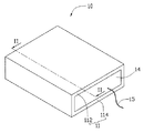
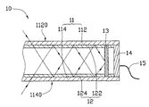
図1及び図2を参照すると、本発明の第一実施形態に係る携帯型電力供給装置10は、透光性を有するハウジング11と、導光素子12と、コンデンサーレンズ13と、光エネルギー変換器14と、電気エネルギー出力素子15と、を備える。
1 and 2, a portable
前記ハウジング11は、中空板状構造であって、頂板112及び底板114を備える。前記頂板112の頂面1120は、前記ハウジング11の第一光入射面であって、前記底板114の底面1140は、前記ハウジング11の第二光入射面である。太陽光は、前記頂板112の頂面1120及び前記底板114の底面1140から前記ハウジング11の内部に入射する。前記頂板112及び前記底板114は、第一屈折率を有する。
The
前記導光素子12は、対向設置される第一反射板122及び第二反射板124を備える。前記第一反射板122は、前記頂板112の底面に貼り合わせられ、前記第二反射板124は、前記底板114の頂面に貼り合わせられる。前記第一反射板122及び前記第二反射板124は、前記第一屈折率より大きい第二屈折率を有する。
The
前記光エネルギー変換器14は、前記ハウジング11の内部に設置され、且つ前記導光素子12の近傍に位置し、光エネルギーを電気エネルギーに変換することに用いられる。本実施形態において、前記光エネルギー変換器14は、太陽電池板である。
The
前記コンデンサーレンズ13は、前記ハウジング11の内部に設置され、具体的に前記光エネルギー変換器14の前記導光素子12に隣り合う片側に設置されて、前記導光素子12からの光線を前記光エネルギー変換器14に集めることに用いられる。
The
前記電気エネルギー出力素子15は、前記光エネルギー変換器14に電気接続する。前記光エネルギー変換器14により変換された電気エネルギーは、前記電気エネルギー出力素子15により出力する。
The electrical
前記第一屈折率が前記第二屈折率より小さいため、太陽光は、前記頂板112の頂面1120及び前記底板114の底面1140から前記ハウジング11の内部に順調に入射することができる。前記第二屈折率が前記第一屈折率より大きいため、前記導光素子12に入射した太陽光は、前記第一反射板122と前記頂板112とが接触する表面及び前記第二反射板124と前記底板114とが接触する表面で全反射されて、前記コンデンサーレンズ13に効果的に伝送される。前記コンデンサーレンズ13は、前記太陽光を前記光エネルギー変換器14に集め、前記光エネルギー変換器14は、受けた光エネルギーを電気エネルギーに変換して貯蓄する。前記電気エネルギー出力素子15は、前記光エネルギー変換器14に貯蓄された電気エネルギーを出力して、前記携帯型電力供給装置10以外の他の電子装置に電力を持続的に提供する。なお、前記コンデンサーレンズ13により光線を前記光エネルギー変換器14に集中的に集めるため、前記光エネルギー変換器14の光電変換効率が高い。
Since the first refractive index is smaller than the second refractive index, sunlight can smoothly enter the inside of the
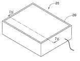
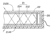
図3及び図4を参照すると、本発明の第二実施形態に係る携帯型電力供給装置20は、前記第一実施形態に係る携帯型電力供給装置10に比べて、保護層28を更に備える。
Referring to FIGS. 3 and 4, the portable
前記保護層28は、前記携帯型電力供給装置20のハウジング21の外表面を覆って、衝撃、強い光線、湿気などの不利要素によって、前記携帯型電力供給装置20が損傷を受けることを防ぐ。前記保護層28の材料は、透光材料又は非透光材料である。前記保護層28の材料が透光材料である場合、前記保護層28で前記ハウジング21の外表面全体を覆って、前記携帯型電力供給装置20が備える他の素子を全て前記保護層28によって覆うことができる。前記保護層28の材料が非透光材料である場合、前記保護層28で前記ハウジング21の一部分の外表面を覆って、頂板212の頂面2120と底板214の底面2140の中の少なくとも一方を暴露させる。本実施形態において、前記頂板212の頂面2120が外部に暴露され、太陽光が前記頂板212の頂面2120から前記ハウジング21内部の導光素子22に入射する。
The
前記携帯型電力供給装置20の作動原理と前記携帯型電力供給装置10の作動原理が同様であるので、それに対する詳細な説明を省略する。
Since the operation principle of the portable
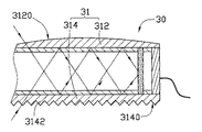
図5を参照すると、本発明の第三実施形態に係る携帯型電力供給装置30は、前記第一実施形態に係る携帯型電力供給装置10とほぼ同じであるが、頂板312の頂面3120が曲面であって、底板314の底面3140には、複数の突出部3142が設置されているため、前記頂面3120と前記底面3140は、平面に相対して比較的大きい面積を有し、従って前記携帯型電力供給装置30に入射する光量を増加し、光エネルギー変換器34の光電変換効率を高めることができる。
Referring to FIG. 5, the portable
前記頂板312の頂面3120及び前記底板314の底面3140の両方が全て曲面であるか、又はその中の一方が平面であることができる。前記頂板312の頂面3120及び前記底板314の底面3140全てに複数の突出部3142を設置することもできる。
Both the
図6及び図7を参照すると、本発明の第四実施形態に係る携帯型電力供給装置40は、透光性を有するハウジング41と、導光素子42と、コンデンサーレンズ43と、光エネルギー変換器44と、電気エネルギー出力素子45と、を備える。
6 and 7, a portable
前記ハウジング41は、中空円柱状構造であって、第一屈折率を有する。
The
前記導光素子42は、前記ハウジング41の内部に設置され、且つ前記ハウジング41の内側壁に貼り合わせられる。前記導光素子42は、前記第一屈折率より大きい第二屈折率を有する。
The
前記光エネルギー変換器44は、前記ハウジング41の内部に設置され、且つ前記導光素子42の近傍に位置し、光エネルギーを電気エネルギーに変換することに用いられる。本実施形態において、前記光エネルギー変換器44は、太陽電池板である。
The
前記コンデンサーレンズ43は、前記ハウジング41の内部に設置され、具体的に前記光エネルギー変換器44の前記導光素子42に隣り合う片側に設置されて、前記導光素子42からの光線を前記光エネルギー変換器44に集めることに用いられる。
The
前記電気エネルギー出力素子45は、前記光エネルギー変換器44に電気接続する。前記光エネルギー変換器44により変換された電気エネルギーは、前記電気エネルギー出力素子45により出力する。
The electric
前記携帯型電力供給装置40の作動原理と前記携帯型電力供給装置10の作動原理が同様であるので、それに対する詳細な説明を省略する。
Since the operation principle of the portable
以上本発明を実施例に基づいて具体的に説明したが、本発明は、上述の実施例に限定されるものではなく、その要旨を逸脱しない範囲において、種種変更可能であることは勿論であって、本発明の保護範囲は、以下の特許請求の範囲から決まる。 The present invention has been specifically described above based on the embodiments. However, the present invention is not limited to the above-described embodiments, and it goes without saying that various modifications can be made without departing from the scope of the present invention. Thus, the protection scope of the present invention is determined from the following claims.
10,20,30,40 携帯型電力供給装置
11,21,41 ハウジング
12,22,42 導光素子
13,43 コンデンサーレンズ
14,34,44 光エネルギー変換器
15,45 電気エネルギー出力素子
28 保護層
112,212,312 頂板
114,214,314 底板
122 第一反射板
124 第二反射板
1120,2120,3120 頂面
1140,2140,3140 底面
3142 突出部
10, 20, 30, 40 Portable
Claims (9)
前記ハウジングの内表面に接触し、且つ前記第一屈折率より大きい第二屈折率を有する導光素子と、
前記ハウジングの内部に設置され、且つ前記導光素子の近傍に位置し、光エネルギーを電気エネルギーに変換する光エネルギー変換器と、
前記ハウジングの内部に設置され、且つ前記光エネルギー変換器の前記導光素子に隣り合う片側に位置し、前記導光素子が伝送する光線を前記光エネルギー変換器に集めるコンデンサーレンズと、
前記光エネルギー変換器に電気接続し、且つ前記光エネルギー変換器により変換された電気エネルギーを出力する電気エネルギー出力素子と、
を備えることを特徴とする携帯型電力供給装置。 A hollow housing for receiving sunlight from the outer surface of at least a portion thereof and having a first refractive index;
A light guide element in contact with the inner surface of the housing and having a second refractive index greater than the first refractive index;
A light energy converter installed inside the housing and located in the vicinity of the light guide element, for converting light energy into electrical energy;
A condenser lens installed inside the housing and located on one side of the light energy converter adjacent to the light guide element, and collecting the light transmitted by the light guide element on the light energy converter;
An electrical energy output element that is electrically connected to the optical energy converter and outputs electrical energy converted by the optical energy converter;
A portable power supply device comprising:
Applications Claiming Priority (1)
| Application Number | Priority Date | Filing Date | Title |
|---|---|---|---|
| CN2008103062589A CN101752441B (en) | 2008-12-15 | 2008-12-15 | Portable power supply device |
Publications (1)
| Publication Number | Publication Date |
|---|---|
| JP2010141337A true JP2010141337A (en) | 2010-06-24 |
Family
ID=42239104
Family Applications (1)
| Application Number | Title | Priority Date | Filing Date |
|---|---|---|---|
| JP2009280885A Pending JP2010141337A (en) | 2008-12-15 | 2009-12-10 | Mobile power supply device |
Country Status (4)
| Country | Link |
|---|---|
| US (1) | US20100147382A1 (en) |
| JP (1) | JP2010141337A (en) |
| KR (1) | KR20100069575A (en) |
| CN (1) | CN101752441B (en) |
Families Citing this family (6)
| Publication number | Priority date | Publication date | Assignee | Title |
|---|---|---|---|---|
| TWI445194B (en) * | 2010-12-06 | 2014-07-11 | Ind Tech Res Inst | Package structure of solar photovoltaic module and method of manufacturing the same |
| US20120214556A1 (en) * | 2011-02-17 | 2012-08-23 | Nokia Corporation | Method and Apparatus for Solar Cell Light Concentrator Panel |
| CN114207845B (en) * | 2019-07-15 | 2024-08-20 | Slt科技公司 | Power photodiode structure, manufacturing method and use method |
| US20220406953A1 (en) * | 2019-07-15 | 2022-12-22 | Slt Technologies, Inc. | Power photodiode structures, methods of making, and methods of use |
| US11575055B2 (en) | 2019-07-15 | 2023-02-07 | SLT Technologies, Inc | Methods for coupling of optical fibers to a power photodiode |
| US11569398B2 (en) * | 2019-07-15 | 2023-01-31 | SLT Technologies, Inc | Power photodiode structures and devices |
Family Cites Families (3)
| Publication number | Priority date | Publication date | Assignee | Title |
|---|---|---|---|---|
| JP3180043B2 (en) * | 1996-12-26 | 2001-06-25 | シャープ株式会社 | Image input device |
| CN2671224Y (en) * | 2003-12-23 | 2005-01-12 | 山东超越数控电子有限公司 | Portable solar power supplier |
| CN101267006B (en) * | 2007-11-08 | 2010-08-18 | 北京恒基伟业投资发展有限公司 | Power supply device for solar mobile terminal mad of multiple photoelectrical material |
-
2008
- 2008-12-15 CN CN2008103062589A patent/CN101752441B/en not_active Expired - Fee Related
-
2009
- 2009-11-09 US US12/615,249 patent/US20100147382A1/en not_active Abandoned
- 2009-12-01 KR KR1020090117841A patent/KR20100069575A/en not_active Withdrawn
- 2009-12-10 JP JP2009280885A patent/JP2010141337A/en active Pending
Also Published As
| Publication number | Publication date |
|---|---|
| CN101752441A (en) | 2010-06-23 |
| US20100147382A1 (en) | 2010-06-17 |
| CN101752441B (en) | 2012-05-23 |
| KR20100069575A (en) | 2010-06-24 |
Similar Documents
| Publication | Publication Date | Title |
|---|---|---|
| US8776783B2 (en) | Solar energy collector and solar energy module having same | |
| CN101752441B (en) | Portable power supply device | |
| EP1662582A3 (en) | Solar cell module | |
| JP2013513938A (en) | Reflective element for photovoltaic modules with double-sided cells | |
| KR101099375B1 (en) | Multi-reflective solar condensing structure | |
| JP5504715B2 (en) | Lighting device | |
| US9231144B2 (en) | Light collecting module | |
| JP2012044024A (en) | Solar battery module | |
| WO2008087690A1 (en) | Light collecting sheet type solar battery | |
| JP2009117446A (en) | Condensing sheet solar power generator | |
| JP7306359B2 (en) | Photoelectric conversion device for photovoltaic power generation | |
| JP2012099681A (en) | Light condensing structure and photovoltaics generator | |
| JP2010055789A (en) | Portable illumination device | |
| JP2020513159A (en) | Solar cell module | |
| JP2014211084A (en) | Roof structure with luminaire, and roof for carport and roof for waiting space using the same | |
| KR200459976Y1 (en) | Cover of panel for focusing of solar cell | |
| CN201732793U (en) | Solar cell panel | |
| TWM465556U (en) | Solar energy module | |
| TWM356016U (en) | A solar reflective and refractive dual light-collecting device | |
| CN217280801U (en) | Improved generation photovoltaic module with clearance reflection of light structure | |
| TW201029201A (en) | Portable power supply device | |
| TWI552368B (en) | High power condenser for solar cells | |
| JP3151300U (en) | Solar power plant | |
| CN201178051Y (en) | Key module with electric power storage function | |
| JP2009092379A (en) | Electronic watch with solar cell |