JP2010141380A - Radio transmitter, and radio communication system - Google Patents
Radio transmitter, and radio communication system Download PDFInfo
- Publication number
- JP2010141380A JP2010141380A JP2008312896A JP2008312896A JP2010141380A JP 2010141380 A JP2010141380 A JP 2010141380A JP 2008312896 A JP2008312896 A JP 2008312896A JP 2008312896 A JP2008312896 A JP 2008312896A JP 2010141380 A JP2010141380 A JP 2010141380A
- Authority
- JP
- Japan
- Prior art keywords
- signal
- wireless
- code string
- frequency
- radio
- Prior art date
- Legal status (The legal status is an assumption and is not a legal conclusion. Google has not performed a legal analysis and makes no representation as to the accuracy of the status listed.)
- Granted
Links
Images

Landscapes
- Channel Selection Circuits, Automatic Tuning Circuits (AREA)
- Digital Transmission Methods That Use Modulated Carrier Waves (AREA)
- Transmitters (AREA)
Abstract
【課題】通信時間が増大するおそれを低減しつつ、無線受信装置におけるIFフィルタの通過帯域幅を狭くすることが容易な無線送信装置、及び無線通信システムを提供する。
【解決手段】無線信号の周波数を、搬送波周波数から偏移させることによって変調し、当該変調された無線信号を無線受信装置へ送信する無線送信装置であって、連続する、n(nは整数)個の論理値「1」を示す符号と、連続する、n個の論理値「0」を示す符号とが交互に繰り返されるビット同期符号列と、ビット同期符号列の後に続き、通信によって伝えたいデータを含むデータ符号列とに対応する信号を生成する信号生成部SGと、信号生成部SGによって生成された信号を変調して得られた無線信号を送信する送信RF回路TRFとを備え、信号生成部SGは、ビット同期符号列の実効的な通信速度を、データ符号列の通信速度より遅くするように、ビット同期符号列を生成するようにした。
【選択図】図4Provided are a wireless transmission device and a wireless communication system that can easily reduce the passband width of an IF filter in a wireless reception device while reducing the possibility of an increase in communication time.
A radio transmission apparatus that modulates a frequency of a radio signal by shifting from a carrier frequency and transmits the modulated radio signal to a radio reception apparatus, and is continuous, n (n is an integer) The bit synchronization code string in which the code indicating the logical value “1” and the code indicating the n logical values “0” are alternately repeated, and the bit synchronization code string follow the bit synchronization code string, and is transmitted by communication A signal generation unit SG that generates a signal corresponding to a data code string including data, and a transmission RF circuit TRF that transmits a radio signal obtained by modulating the signal generated by the signal generation unit SG. The generation unit SG generates the bit synchronization code string so that the effective communication speed of the bit synchronization code string is slower than the communication speed of the data code string.
[Selection] Figure 4
Description
本発明は、FSK(Frequency Shift Keying)、又はFM(Frequency Modulation)変調方式の無線送信装置、及びこれを用いた無線通信システムに関する。 The present invention relates to a radio transmission apparatus using FSK (Frequency Shift Keying) or FM (Frequency Modulation) modulation, and a radio communication system using the same.
高精細な画像や動画など大容量のデータを伝送する無線通信システムにおいて、高速な通信速度が要求されるのは言うまでもないが、機器の制御信号など比較的小容量のデータを伝送する無線通信システムにおいても高速な通信速度が要求される場合がある。その一例は、送信器が電池を電源として駆動している場合である。 In a wireless communication system that transmits a large amount of data such as high-definition images and moving images, it is needless to say that a high communication speed is required, but a wireless communication system that transmits a relatively small amount of data such as a control signal of a device. In some cases, a high communication speed may be required. One example is a case where the transmitter is driven by a battery as a power source.
電池駆動の送信器においては、その消費電力を低減することが特に強く求められる。消費電力を低減することにより、小型の電池が使用可能になり機器を小型化できる、電池交換や充電の必要がなくなる(または頻度を少なくすることができる)ためメンテナンス性が向上したり、電池交換や充電が可能な構造をとる必要がなくなり機器の小型化や低コスト化ができたりするなど、様々な利点を得ることができる。 In battery-powered transmitters, it is particularly strongly required to reduce power consumption. By reducing power consumption, small batteries can be used and the equipment can be miniaturized. There is no need for battery replacement or charging (or frequency can be reduced), so maintenance is improved and battery replacement is possible. In addition, it is not necessary to adopt a structure that can be charged and various advantages can be obtained, such as downsizing and cost reduction of the device.
送信器の消費電力を低減する方法の1つとして、通信時間を短縮することが挙げられる。ある容量のデータを送信する場合に、通信時間を短縮するほど送信器を駆動させる時間を短くすることができる。その結果、消費電力を低減できる。 One method for reducing the power consumption of the transmitter is to shorten the communication time. When transmitting a certain amount of data, the time for driving the transmitter can be shortened as the communication time is shortened. As a result, power consumption can be reduced.
図11は、背景技術に係る無線通信システムの構成を示すブロック図である。図11に示す無線通信システムは、無線送信装置100と、無線受信装置110とを備えている。無線送信装置100は、送信制御回路106、信号生成部101、無線送信部102、パワーアンプ103、送信アンテナ104、及び発振器105から構成される。
FIG. 11 is a block diagram illustrating a configuration of a wireless communication system according to the background art. The wireless communication system illustrated in FIG. 11 includes a
送信制御回路106は送信トリガを検出すると、発振器105と信号生成部101とを動作させる。
The
無線送信部102は、発振器105から出力される正弦波信号を、信号生成部101から出力される送信データで変調し、その変調信号をパワーアンプ103に送出する。発振器105の発振周波数は、搬送波の周波数として用いられる。
The
パワーアンプ103は変調信号を増幅し、送信アンテナ104に伝達して、送信アンテナ104より空間に放射する。
The
無線受信装置110は、受信アンテナ111、ローノイズアンプ112、RFフィルタ113、ミキサ114、IF(Intermediate Frequency)フィルタ115、IFアンプ116、検波器117、ベースバンド回路部118、自動周波数調整回路119、及び局部発振回路120から構成される。
The
受信アンテナ111で受信された高周波信号は、ローノイズアンプ112で増幅されRFフィルタ113で不要周波数成分を除去された後、ミキサ114によって局部発振回路120から出力される局部発振周波数の出力信号とミキシングされ、IF信号に変換される。IF信号はIFフィルタ115にて不要周波数成分を除去された後IFアンプ116で増幅され、検波器117によって周波数−電圧変換された後、ベースバンド回路部118に伝達される。
The high frequency signal received by the
ここで、無線送信装置100の搬送波周波数と無線受信装置110の局部発振周波数とが、温度の影響を受けるなどして互いに設計値からずれている場合、IF信号のIF周波数が設計値から外れる。このとき、検波器117によって周波数−電圧変換された信号も、設計値から外れてしまい、受信感度が低下する。
Here, when the carrier frequency of the
そこで、検波器117の出力信号が自動周波数調整回路119に入力されるようになっている。そして、自動周波数調整回路119によって、IF周波数が設計値に収束するように局部発振回路120の局部発振周波数の設計値からの偏差(ずれ量)と、無線送信装置100の搬送波周波数の設計値からの偏差(ずれ量)とが等しくなるように調節されて、受信感度の低下が抑制されるようになっている(例えば、特許文献1参照。)。
Therefore, the output signal of the
また、一般に、FSK変調方式やFM変調方式の無線通信システムにおいて、通信速度を高速にするほど、変調信号の周波数スペクトラムが広がるため、それに応じて無線受信装置110に設けられているIFフィルタ115の通過帯域幅を広く設計する必要がある。
In general, in a radio communication system using the FSK modulation scheme or the FM modulation scheme, the frequency spectrum of the modulation signal is broadened as the communication speed is increased. Accordingly, the
変調周波数をfMOD、周波数偏移をfDEVとすると、IFフィルタ115に要求される通過帯域幅BIF’は近似的に下記の式(2)で表される(カーソン則)。
When the modulation frequency is f MOD and the frequency shift is f DEV , the pass bandwidth B IF ′ required for the
BIF’≧2×(fMOD+fDEV) ・・・(2)
さらに、無線通信システムの低コスト化を図るために、無線送信装置100側の発振器105や無線受信装置110の局部発振回路120に、温度補償機能をもたない低コストの発振器を使用する場合がある。このような場合、送受信器それぞれの基準発振周波数の温度変化をも考慮する必要があるため、IFフィルタ115に要求される通過帯域幅BIFは、下記の式(3)で示される。
B IF '≧ 2 × (f MOD + f DEV ) (2)
Furthermore, in order to reduce the cost of the wireless communication system, a low-cost oscillator having no temperature compensation function may be used for the
BIF≧2×(fMOD+fDEV+△fTXMAX+△fRXMAX) ・・・(3)
ここで、△fTXMAXは送信装置側における基準発振周波数の最大偏差(偏差の絶対値の最大値)、△fRXMAXは受信装置側における基準発振周波数の最大偏差(偏差の絶対値の最大値)である。
B IF ≧ 2 × (f MOD + f DEV + Δf TXMAX + Δf RXMAX ) (3)
Here, Δf TXMAX is the maximum deviation of the reference oscillation frequency on the transmitter side (maximum value of the deviation), and Δf RXMAX is the maximum deviation of the reference oscillation frequency on the side of the receiver (the maximum value of the absolute value of deviation). It is.
一方、受信器の受信感度SSは、一般に下記の式(4)で表される。 On the other hand, the receiver sensitivity SS of the receiver is generally expressed by the following equation (4).
SS[dBm]= −174[dBm]+10logF+10logBIF+10log(S/N) ・・・(4)
ここで、−174[dBm]は、50Ω系における通過帯域幅BIF=1[Hz]、室温290[K]の条件における熱雑音電力、Fは受信器の雑音指数、10logBIFは通過帯域幅BIFによる雑音電力の変化分、10log(S/N)は受信器として必要なSN比(信号対雑音比)である。
SS [dBm] = − 174 [dBm] +10 log F + 10 log B IF + 10 log (S / N) (4)
Here, -174 [dBm] is the pass bandwidth B IF = 1 [Hz] in the 50Ω system, the thermal noise power under the condition of room temperature 290 [K], F is the noise figure of the receiver, and 10 log B IF is the pass bandwidth. The amount of change in noise power due to B IF , 10 log (S / N) is the SN ratio (signal-to-noise ratio) required for the receiver.
受信感度SSは、無線受信装置110が無線信号を正常に復調するために最低限必要な受信電力であるから、受信感度SSが小さいほど無線受信装置110の感度がよいことを示している。そうすると、式(4)から、IFフィルタ115の通過帯域幅BIFが狭い(値が小さい)ほど、雑音電力の影響が低減されて無線受信装置110の受信感度が向上することが明らかである。さらに、IFフィルタ115の通過帯域幅BIFが狭いほど、隣接チャネル選択度が向上するという利点が得られる。
The reception sensitivity SS is the minimum reception power required for the
しかしながら、変調信号を確実に通過させるためにはIFフィルタ115の通過帯域幅BIFは式(3)を満足する必要があるため、通信速度が高速(従って変調周波数fMODの値が大きくなる)ほどIFフィルタ115の通過帯域幅BIFを広く(大きく)せざるを得ない。
However, since the pass bandwidth B IF of the
ここで、自動周波数調整回路119は、送受信器間での基準発振周波数のズレを補正するために、検波器117の出力信号からIF周波数のズレ(=搬送波周波数の設計値からの偏差と局部発振周波数の設計値からの偏差との差)を検知し、その検知結果を元に局部発振回路120の基準発振周波数を調整してIF周波数のズレを補正する。
Here, the automatic
自動周波数調整回路119による自動周波数調整の完了後は、IF周波数のズレがほぼゼロになるため、検波器117を最も高感度な周波数において動作させることができる。正常な復調動作を行うためには、自動周波数調整回路119は、当該通信システムにおける通信プロトコルにおいて、同一符号が連続する可能性のある最大の数と、ビット長との積に対して十分大きい時定数を持つ必要がある。
After the automatic frequency adjustment by the automatic
そのため、受信を開始してから周波数の調整が完了するまで、時定数に応じた時間がかかってしまうことになる。そして、受信開始から周波数調整完了までの間は、搬送波周波数の設計値からの偏差と局部発振周波数の設計値からの偏差との差が無視できない。 Therefore, it takes time corresponding to the time constant from the start of reception until the frequency adjustment is completed. Then, during the period from the start of reception to the completion of frequency adjustment, the difference between the deviation from the design value of the carrier frequency and the deviation from the design value of the local oscillation frequency cannot be ignored.
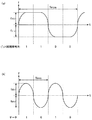
図12は、図11に示す無線通信システムの動作の一例を示す説明図である。無線送信装置100から送信される無線信号は、図12(a)に示すように、大別するとビット同期信号、フレーム同期信号およびデータの3つに分けられる。ビット同期信号は、受信器との間でビット同期をとるための信号で、1010・・・の繰り返し信号である。フレーム同期信号は、受信器との間でフレーム同期をとるための信号で、通信システムに応じて特定のパターンが設定される。データは、実際に通信したい情報を含むビット列で、通信内容によって異なり、一般にはランダムなパターンとなる。
FIG. 12 is an explanatory diagram showing an example of the operation of the wireless communication system shown in FIG. As shown in FIG. 12A, the radio signal transmitted from the
そして、図12(b)に示すように、IF周波数の設計値をfIF0、自動周波数調整回路119による自動周波数調整の開始からの経過時間をt、時間tにおけるIF周波数の設計値からのずれの絶対値の最大値を△fIF(t)とすると、自動周波数調整が開始されるとき(t=0)の設計値fIF0からのずれの絶対値の最大値△fIF(0)は、△fTXMAX+△fRXMAXとなる。
Then, as shown in FIG. 12B, the IF frequency design value is f IF0 , the elapsed time from the start of automatic frequency adjustment by the automatic
そして、自動周波数調整回路119による自動周波数調整の実行と共に(時間tの経過と共に)、局部発振回路120から出力される発振信号の周波数が調整されて、△fIF(t)は略「0」に収束する。
As the automatic
このように、自動周波数調整が完了した後はIF周波数のズレがほぼ「0」になるものの、通信開始直後は、最大で△fIF(0)=△fTXMAX+△fRXMAXだけ送信側と受信側とでIF周波数がずれる可能性がある。このため、自動周波数調整回路119を備えていても、IFフィルタ115の通過帯域幅BIFは、式(3)を満足する必要がある。従って、図12(c)に示すように、時間t=0において、すくなくともBIF=2×(fMOD+fDEV+△fTXMAX+△fRXMAX)となる。
As described above, after the automatic frequency adjustment is completed, the deviation of the IF frequency becomes almost “0”, but immediately after the start of communication, a maximum of Δf IF (0) = Δf TXMAX + Δf RXMAX There is a possibility that the IF frequency shifts with the receiving side. For this reason, even if the automatic
すなわち、基準発振周波数の温度変化が大きい場合、それにしたがってIFフィルタ115の通過帯域幅BIFも広く(大きく)する必要がある。その結果、式(4)に従い受信感度SSが劣化(増大)することになる。
That is, when the temperature change of the reference oscillation frequency is large, the pass bandwidth B IF of the
そこで、自動周波数調整が完了するまでの間、無線送信装置100がダミー信号を送信し続けることで、無線受信装置110側のIFフィルタ115の通過帯域幅BIFを小さくできるようにする通信システムが知られている。
Thus, there is a communication system that allows the
図13は、このような無線通信システムの動作を説明するための説明図である。無線送信装置100は、まず無変調の(搬送波周波数の)ダミー信号を送信し、無線受信装置110における自動周波数調整が完了後、本来送りたい信号を送信する。これにより、無線受信装置110が受信を開始するときは、無線信号(ダミー信号)には変調周波数fMODと、周波数偏移fDEVとが含まれないので、IFフィルタ115に必要とされる通過帯域幅BIFは、図13(c)に示すように、2×(△fTXMAX+△fRXMAX)となり、図12(c)に示す通過帯域幅BIFよりも小さくなるので、ダミー信号を用いない場合よりも通過帯域幅BIFの小さいIFフィルタ115を使用可能となる。
しかしながら、上述のように、ダミー信号を付加すると、その分トータルの通信時間が長くなり、無線送信装置100の消費電力が増加してしまうという問題がある。前述のように、特に電池駆動の送信装置においては、消費電力低減が強く求められており、消費電力増加のデメリットは大きい。
However, as described above, when a dummy signal is added, there is a problem that the total communication time is increased correspondingly, and the power consumption of the
本発明の目的は、通信時間が増大するおそれを低減しつつ、無線受信装置におけるIFフィルタの通過帯域幅を狭くすることが容易な無線送信装置、及び無線通信システムを提供することである。 An object of the present invention is to provide a wireless transmission device and a wireless communication system that can easily reduce the passband width of an IF filter in a wireless reception device while reducing the possibility of an increase in communication time.
本発明に係る無線送信装置は、無線信号の周波数を、搬送波周波数から偏移させることによって変調し、当該変調された無線信号を無線受信装置へ送信する無線送信装置であって、連続する、n(nは整数)個の論理値「1」を示す符号と、連続する、n個の論理値「0」を示す符号とが交互に繰り返される第1符号列と、当該第1符号列の後に続き、通信によって伝えたいデータを含む第2符号列とに対応する信号を生成する信号生成部と、前記信号生成部によって生成された信号に応じて前記変調を行い、当該変調された無線信号を送信する送信部とを備え、前記信号生成部は、前記第1符号列の実効的な通信速度を、前記第2符号列の通信速度より遅くするように、前記第1符号列を生成する。 A radio transmission apparatus according to the present invention is a radio transmission apparatus that modulates a frequency of a radio signal by shifting it from a carrier frequency, and transmits the modulated radio signal to the radio reception apparatus, and is continuous, n (N is an integer) a first code string in which a code indicating a logical value “1” and consecutive codes indicating a logical value “0” are alternately repeated, and after the first code string Subsequently, a signal generation unit that generates a signal corresponding to the second code string including data to be transmitted by communication, the modulation according to the signal generated by the signal generation unit, and the modulated radio signal A transmission unit for transmitting, and the signal generation unit generates the first code string so that an effective communication speed of the first code string is slower than a communication speed of the second code string.
この構成によれば、第1符号列に応じて変調された無線信号は、通信によって伝えたいデータを含む第2符号列を示す無線信号より通信速度が実効的に遅くなっているため、無線信号の周波数帯域幅が狭くなっている。したがって、この無線信号が受信装置で受信された場合、受信装置における自動周波数調整の完了前においてもIFフィルタの通過帯域幅を狭くすることが容易である。さらに第2符合列を送信するときは第1符号列より早い通信速度でデータを送信できるので、通信時間が増大するおそれが少ない。これにより、通信時間が増大するおそれを低減しつつ、受信装置のIFフィルタの通過帯域幅を狭くすることが容易となる。 According to this configuration, the wireless signal modulated according to the first code string has a communication speed that is effectively slower than the wireless signal indicating the second code string including the data to be transmitted by communication. The frequency bandwidth is narrow. Therefore, when this radio signal is received by the receiving device, it is easy to narrow the pass band width of the IF filter even before the automatic frequency adjustment in the receiving device is completed. Furthermore, when transmitting the second code sequence, data can be transmitted at a higher communication speed than the first code sequence, so there is little risk of an increase in communication time. As a result, it is easy to narrow the passband width of the IF filter of the receiving device while reducing the possibility of increasing the communication time.
また、前記第1符号列は、前記第1送信部によって送信される無線信号を受信する無線受信装置がビット同期をとるためのビット同期符号列であることが好ましい。 Moreover, it is preferable that the first code string is a bit synchronization code string for allowing a radio reception apparatus that receives a radio signal transmitted by the first transmission unit to perform bit synchronization.
この構成によれば、第1符号列をビット同期符号列とすることにより、無線送信装置は第1符号列と別にビット同期符号列を送信する必要がなくなる。これにより、通信時間が増大するおそれを低減しつつ、受信装置のIFフィルタの通過帯域幅を狭くすることが容易となる。 According to this configuration, since the first code string is the bit synchronization code string, the wireless transmission device does not need to transmit the bit synchronization code string separately from the first code string. As a result, it is easy to narrow the passband width of the IF filter of the receiving device while reducing the possibility of increasing the communication time.
また、前記第1符号列の継続時間は、前記無線受信装置において、受信された無線信号に基づき受信しようとする無線信号の周波数を調整する自動周波数調整を実行するために必要となる時間として予め設定された調整時間以上に設定されていることが好ましい。 In addition, the duration of the first code string is set in advance as a time required for executing automatic frequency adjustment for adjusting the frequency of a radio signal to be received based on the received radio signal in the radio reception apparatus. It is preferable that the time is set longer than the set adjustment time.
この構成によれば、無線受信装置において、自動周波数調整が完了するまで第1符号列の受信が継続するので、自動周波数調整の完了前に第2符号列の送信が開始されて通信速度が増大し、受信装置においてIFフィルタの通過帯域幅が不足したり、その結果受信感度が低下したりするおそれが低減される。 According to this configuration, since the reception of the first code string is continued until the automatic frequency adjustment is completed in the wireless reception device, the transmission of the second code string is started before the automatic frequency adjustment is completed and the communication speed is increased. In addition, it is possible to reduce the possibility that the IF filter pass bandwidth is insufficient in the receiving apparatus, and as a result, reception sensitivity is lowered.
また、前記送信部によって、前記変調された無線信号の送信が開始される前に無変調の無線信号を送信させる無変調送信部をさらに備え、前記無変調の無線信号の継続時間と前記第1符号列の継続時間との合計が、前記無線受信装置において、受信された無線信号に基づき受信しようとする無線信号の周波数を調整する自動周波数調整を実行するために必要となる時間として予め設定された調整時間以上に設定されていることが好ましい。 The transmitter further includes a non-modulated transmitter that transmits a non-modulated radio signal before transmission of the modulated radio signal is started, and the duration of the non-modulated radio signal and the first The total of the duration of the code string is set in advance as the time required to execute automatic frequency adjustment for adjusting the frequency of the radio signal to be received based on the received radio signal in the radio reception device. The adjustment time is preferably set to be longer than the adjustment time.
この構成によれば、第1符号列の前に無変調信号が付加されるため、無線受信装置において、受信開始時に必要なIFフィルタの通過帯域幅をさらに狭くすることが容易となる。また、背景技術のように、調整時間の間、ダミー信号を送信し続ける必要がない。これにより、このような背景技術よりも通信時間が増大するおそれを低減することができる。さらに、無線受信装置において自動周波数調整が完了するまで無変調信号とそれに続く第1符合列が継続するので、自動周波数調整の完了前に第2符号列の送信が開始されて通信速度が増大し、受信装置においてIFフィルタの通過帯域幅が不足したり、その結果受信感度が低下したりするおそれが低減される。 According to this configuration, since an unmodulated signal is added before the first code string, it is easy to further narrow the pass band width of the IF filter required at the start of reception in the radio reception apparatus. Further, unlike the background art, it is not necessary to keep transmitting the dummy signal during the adjustment time. Thereby, it is possible to reduce the possibility that the communication time is increased as compared with such background art. Furthermore, since the non-modulated signal and the first code sequence that follows are continued until the automatic frequency adjustment is completed in the wireless receiver, transmission of the second code sequence is started before the automatic frequency adjustment is completed, and the communication speed is increased. The risk that the IF filter pass bandwidth is insufficient in the receiving apparatus or the reception sensitivity is lowered as a result is reduced.
また、前記信号生成部は、前記nを2以上の整数とすることにより、前記第1符号列の実効的な通信速度を、前記第2符号列の通信速度の1/nに減じることが好ましい。 The signal generator preferably reduces the effective communication speed of the first code string to 1 / n of the communication speed of the second code string by setting n to an integer of 2 or more. .
この構成によれば、第1符号列において、論理値「1」を示す符号、及び論理値「0」を示す符号それぞれの連続数を2以上にすることで、第1符号列の実効的な通信速度を、第2符号列の1/nに減じることができるので、第1符号列の送信における通信速度の制御が容易である。 According to this configuration, in the first code string, the number of consecutive codes each indicating the logical value “1” and the code indicating the logical value “0” is set to 2 or more, so that Since the communication speed can be reduced to 1 / n of the second code string, it is easy to control the communication speed in the transmission of the first code string.
また、前記信号生成部は、前記nを1とし、前記第1符号列における論理値「1」を示す符号及び論理値「0」を示す符号それぞれについて、一符号の継続時間を、前記第2符号列における一符号の継続時間より長くすることによって、前記第1符号列の実効的な通信速度を前記第2符号列の通信速度より減じるようにしてもよい。 Further, the signal generation unit sets n to 1, and sets the duration of one code for each of a code indicating a logical value “1” and a code indicating a logical value “0” in the first code string, The effective communication speed of the first code string may be reduced from the communication speed of the second code string by making it longer than the duration of one code in the code string.
この構成によれば、第1符号列における一符号の継続時間を、第2符号列における一符号の継続時間より長くすることによって、第1符号列の実効的な通信速度を第2符号列の通信速度より遅くすることができる。 According to this configuration, by setting the duration of one code in the first code sequence to be longer than the duration of one code in the second code sequence, the effective communication speed of the first code sequence is increased. It can be slower than the communication speed.
また、本発明に係る無線通信システムは、上述の無線送信装置と、前記無線信号を受信する無線受信装置とを備え、前記無線受信装置は、前記無線信号を受信する受信部と、局部発振周波数の発振信号を生成する局部発振部と、前記受信部によって取得された受信信号と前記局部発振部によって生成された発振信号とを混合し、前記受信信号を中間周波数に変換して中間周波数信号を生成する混合部と、記混合部で生成された中間周波数信号を濾波する中間周波数フィルタと、前記中間周波数フィルタによって濾波された信号を復調する復調部と、前記受信部によって受信された前記無線信号に基づいて、前記無線送信装置から送信される無線信号の搬送波周波数の予め設定された設計値からの偏差と前記局部発振周波数の予め設定された設計値からの偏差との差を低減するように前記局部発振周波数を調整する自動周波数調整部とを備え、前記中間周波数フィルタの通過帯域幅BIFは、前記無線信号の変調周波数をfMOD、前記設定偏移量をfDEV、前記搬送波周波数の設計値からのずれの最大値である搬送波周波数最大偏差を△fTXMAX、前記局部発振周波数の設計値からのずれの最大値である局部発振周波数最大偏差を△fRXMAXとすると、下記の式(1)
BIF < 2×(fMOD+fDEV+△fTXMAX+△fRXMAX) ・・・(1)
を満たすように設定されている。
A wireless communication system according to the present invention includes the above-described wireless transmission device and a wireless reception device that receives the wireless signal, and the wireless reception device includes a reception unit that receives the wireless signal, and a local oscillation frequency. The local oscillation unit that generates the oscillation signal of the above, the reception signal acquired by the reception unit and the oscillation signal generated by the local oscillation unit are mixed, and the reception signal is converted into an intermediate frequency to convert the intermediate frequency signal A generating unit; an intermediate frequency filter for filtering the intermediate frequency signal generated by the mixing unit; a demodulating unit for demodulating the signal filtered by the intermediate frequency filter; and the radio signal received by the receiving unit On the basis of the deviation of the carrier frequency of the radio signal transmitted from the radio transmitter from a preset design value and the preset setting of the local oscillation frequency. And an automatic frequency adjusting unit that adjusts the local oscillation frequency so as to reduce the difference between the deviation from the values, the intermediate passband width of the frequency filter B IF is the modulation frequency of the radio signal f MOD, the The set deviation amount is f DEV , the carrier frequency maximum deviation that is the maximum deviation from the design value of the carrier frequency is Δf TXMAX , and the maximum local oscillation frequency that is the maximum deviation from the design value of the local oscillation frequency When the deviation is Δf RXMAX , the following formula (1)
B IF <2 × (f MOD + f DEV + Δf TXMAX + Δf RXMAX ) (1)
It is set to satisfy.
この構成によれば、上述の無線送信装置を用いることで、背景技術のように、式(3)に基づきIFフィルタに要求される通過帯域幅よりも、通過帯域幅BIFを狭くして受信感度および隣接チャネル選択度を向上させることができる。また、符号としての意味を持たないダミー信号を用いる必要がないので、通信時間が増大するおそれを低減しつつ、無線受信装置におけるIFフィルタの通過帯域幅を狭くすることが容易となる。 According to this configuration, by using the above-described wireless transmission device, reception is performed with the pass bandwidth B IF narrower than the pass bandwidth required for the IF filter based on Expression (3) as in the background art. Sensitivity and adjacent channel selectivity can be improved. In addition, since it is not necessary to use a dummy signal having no meaning as a code, it is easy to narrow the pass band width of the IF filter in the wireless reception device while reducing the possibility of an increase in communication time.
また、前記無線受信装置は、さらに、ユーザの操作指示を受け付ける操作ハンドルと、負荷への給電経路を開閉するスイッチング素子と、前記復調部により復調された信号、及び前記操作ハンドルにより受け付けられた操作指示に応じて、前記開閉部を開閉させるスイッチ制御部とを備えることが好ましい。 In addition, the wireless reception device further includes an operation handle that receives an operation instruction from a user, a switching element that opens and closes a power supply path to a load, a signal demodulated by the demodulation unit, and an operation received by the operation handle It is preferable to include a switch control unit that opens and closes the opening and closing unit according to an instruction.
この構成によれば、無線信号を用いて負荷をオン、オフするスイッチシステムにおいて、上述の無線送信装置を負荷の制御信号を送信する無線送信装置として用いることで、通信時間が増大するおそれを低減しつつ、無線受信装置におけるIFフィルタの通過帯域幅を狭くすることが容易となる。 According to this configuration, in the switch system that turns on and off a load using a radio signal, the above-described radio transmission device is used as a radio transmission device that transmits a load control signal, thereby reducing the possibility of an increase in communication time. However, it becomes easy to narrow the pass band width of the IF filter in the wireless receiver.
このような構成の無線送信装置は、第1符号列に応じて変調された無線信号は、通信によって伝えたいデータを含む第2符号列を示す無線信号より通信速度が実効的に遅くなっているため、無線信号の周波数帯域幅が狭くなっている。したがって、この無線信号が受信装置で受信された場合、受信装置における自動周波数調整の完了前においてもIFフィルタの通過帯域幅を狭くすることが容易である。さらに第2符合列を送信するときは第1符号列より早い通信速度でデータを送信できるので、通信時間が増大するおそれが少ない。これにより、通信時間が増大するおそれを低減しつつ、受信装置のIFフィルタの通過帯域幅を狭くすることが容易となる。 In the wireless transmission device having such a configuration, the wireless signal modulated in accordance with the first code string is effectively slower in communication speed than the wireless signal indicating the second code string including the data to be transmitted by communication. Therefore, the frequency bandwidth of the radio signal is narrowed. Therefore, when this radio signal is received by the receiving device, it is easy to narrow the pass band width of the IF filter even before the automatic frequency adjustment in the receiving device is completed. Furthermore, when transmitting the second code sequence, data can be transmitted at a higher communication speed than the first code sequence, so there is little risk of an increase in communication time. As a result, it is easy to narrow the passband width of the IF filter of the receiving device while reducing the possibility of increasing the communication time.
また、このような構成の無線通信システムは、上述の無線送信装置を用いることで、背景技術のように、式(3)に基づきIFフィルタに要求される通過帯域幅よりも、通過帯域幅BIFを狭くして受信感度および隣接チャネル選択度を向上させることができる。また、符号としての意味を持たないダミー信号を用いる必要がないので、通信時間が増大するおそれを低減しつつ、無線受信装置におけるIFフィルタの通過帯域幅を狭くすることが容易となる。 Further, the wireless communication system having such a configuration uses the above-described wireless transmission device, so that the pass bandwidth B is larger than the pass bandwidth required for the IF filter based on Expression (3) as in the background art. The IF can be narrowed to improve reception sensitivity and adjacent channel selectivity. In addition, since it is not necessary to use a dummy signal having no meaning as a code, it is easy to narrow the pass band width of the IF filter in the wireless reception device while reducing the possibility of an increase in communication time.
以下、本発明に係る実施形態を図面に基づいて説明する。なお、各図において同一の符号を付した構成は、同一の構成であることを示し、その説明を省略する。 Embodiments according to the present invention will be described below with reference to the drawings. In addition, the structure which attached | subjected the same code | symbol in each figure shows that it is the same structure, The description is abbreviate | omitted.
(第1実施形態)
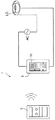
図1は、本発明の一実施形態に係る無線送信装置と、この無線送信装置から送信された無線信号を受信する無線受信装置とを備えた無線通信システムの一例を示す説明図である。図1に示す無線通信システム1は、無線信号を送信する無線送信装置2と、無線信号に応じて照明負荷LDを点滅するスイッチ装置として機能する無線受信装置3とを備えている。無線受信装置3は、照明負荷LDと直列接続されて、電源(商用交流電源)ACに接続されている。なお、負荷は、蛍光灯及び蛍光灯電子安定器などの照明負荷LDに限られず、他の照明負荷や、照明負荷以外の負荷であってもよい。
(First embodiment)
FIG. 1 is an explanatory diagram illustrating an example of a wireless communication system including a wireless transmission device according to an embodiment of the present invention and a wireless reception device that receives a wireless signal transmitted from the wireless transmission device. A
また、無線受信装置3の前面には、操作ハンドル10が設けられている。
An operation handle 10 is provided on the front surface of the
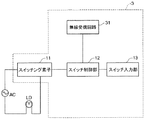
図2は、図1に示す無線受信装置3の構成の一例を示すブロック図である。無線受信装置3は、無線受信回路31、スイッチング素子11、スイッチ制御部12、及びスイッチ入力部13を備えている。
FIG. 2 is a block diagram illustrating an example of the configuration of the
スイッチ入力部13は、例えば操作ハンドル10と連動するように配設されたタクトスイッチを用いて構成されている。スイッチング素子11は、例えばトライアック等のスイッチング素子である。スイッチング素子11は、スイッチ制御部12からの制御信号に応じて照明負荷LDへの給電経路を開閉する。
The
スイッチ制御部12は、例えばマイクロコンピュータを用いて構成されている。そして、スイッチ制御部12は、無線送信装置2から送信され、無線受信回路31によって受信された信号、及びスイッチ入力部13から出力されたオン、オフ信号に応じて、スイッチング素子11を開閉させる。
The
図3は、図2に示す無線受信回路31の構成の一例を示すブロック図である。図3に示す無線受信回路31は、受信アンテナRANT、ローノイズアンプLNA、RFフィルタRFF、ミキサMIX(混合部)、IFフィルタIFF(中間周波数フィルタ)、IFアンプIFA、検波器DTC、ベースバンド回路部RBB、自動周波数調整回路AFC(自動周波数調整部)、及び局部発振回路LOを備えている。この場合、受信アンテナRANT、ローノイズアンプLNA、及びRFフィルタRFFが受信部の一例に相当し、検波器DTC及びベースバンド回路部RBBが復調部の一例に相当している。
FIG. 3 is a block diagram showing an example of the configuration of the
そして、スイッチング素子11のオンオフ指示を示す無線信号が、無線送信装置2から送信され、無線受信回路31の受信アンテナRANTで受信される。受信アンテナRANTで受信された高周波の無線信号は、ローノイズアンプLNAで増幅されRFフィルタRFFで不要周波数成分を除去された後、ミキサMIXによって局部発振回路LOから出力される基準発振周波数(局部発振周波数)の出力信号とミキシングされ、IF信号に変換される。
A wireless signal indicating an on / off instruction of the switching
IF信号はIFフィルタIFFにて不要周波数成分を除去された後IFアンプIFAで増幅され、さらに検波器DTCによって周波数−電圧変換された後ベースバンド回路部RBBに伝達され、さらにベースバンド回路部RBBでベースバンドに変換された受信データが、スイッチ制御部12へ出力される。
The IF signal is freed of unnecessary frequency components by an IF filter IFF, amplified by an IF amplifier IFA, further frequency-voltage converted by a detector DTC, and then transmitted to a baseband circuit unit RBB, and further a baseband circuit unit RBB The reception data converted into the baseband in step S is output to the
これにより、スイッチ制御部12によって、無線送信装置2から送信された無線信号に応じて、スイッチング素子11の開閉が行われる。
Thereby, the
ここで、無線送信装置2の基準発振周波数と無線受信回路31の基準発振周波数とが、温度の影響を受けるなどして互いにずれている場合、IF信号のIF周波数が設計値からずれる。このとき、検波器DTCによって周波数−電圧変換された信号も、設計値からずれてしまい、受信感度が低下する。
Here, when the reference oscillation frequency of the
そこで、検波器DTCの出力信号が自動周波数調整回路AFCに入力される。そして、自動周波数調整回路AFCは、局部発振回路LOの局部発振周波数の設計値からのずれと、無線送信装置100のから送信される無線信号の搬送波周波数の設計値からのずれとが等しくなるように局部発振周波数を調節して、IF周波数を設計値に収束させる。
Therefore, the output signal of the detector DTC is input to the automatic frequency adjustment circuit AFC. Then, the automatic frequency adjustment circuit AFC is configured such that the deviation from the design value of the local oscillation frequency of the local oscillation circuit LO is equal to the deviation from the design value of the carrier frequency of the radio signal transmitted from the
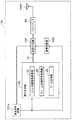
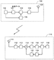
図4は、図1に示す無線送信装置2の構成の一例を示すブロック図である。図4に示す無線送信装置2は、送信制御回路TCC、信号生成部SG、送信RF回路TRF(送信部)、基準発振器OSC、パワーアンプPA、及び送信アンテナTANTを備えている。
FIG. 4 is a block diagram illustrating an example of the configuration of the
送信制御回路TCCは送信トリガを検出すると、基準発振器OSCと信号生成部SGとを動作させる起動回路である。 The transmission control circuit TCC is an activation circuit that operates the reference oscillator OSC and the signal generator SG when a transmission trigger is detected.
信号生成部SGは、例えば所定の演算処理を実行するCPU(Central Processing Unit)と、所定の制御プログラムが記憶されたROM(Read Only Memory)と、データを一時的に記憶するRAM(Random Access Memory)と、これらの周辺回路等とを備えて構成されている。そして、信号生成部SGは、例えばROMに記憶された制御プログラムを実行することにより、ビット同期信号送信部21、フレーム同期信号送信部22、及びデータ送信部23として機能する。
The signal generator SG includes, for example, a central processing unit (CPU) that executes predetermined arithmetic processing, a read only memory (ROM) that stores a predetermined control program, and a random access memory (RAM) that temporarily stores data. ) And these peripheral circuits and the like. The signal generator SG functions as a bit
なお、信号生成部SGは、CPUを用いる例に限られず、例えばステートマシンや論理回路等を用いて構成されていてもよい。 The signal generation unit SG is not limited to an example using a CPU, and may be configured using, for example, a state machine or a logic circuit.
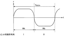
ビット同期信号送信部21は、送信RF回路TRFへ、ビット同期を取るためのビット同期符号列(第1符号列)を表す信号S1を、送信RF回路TRFへ送信することで、送信RF回路TRFによってビット同期信号を送信させる。ビット同期符号列は、連続する、n(nは2以上の整数)個の論理値「1」を示す符号と、連続する、n個の論理値「0」を示す符号とが交互に繰り返されて構成されている。
The bit synchronization
ビット同期信号送信部21は、例えば、n=2の場合、11001100・・・を繰り返すビット同期符号列を生成し、n=3の場合、111000111000・・・を繰り返すビット同期符号列を生成し、信号S1として送信RF回路TRFへ出力する。そうすると、例えばn=2の場合、図5(a)に示すように、送信RF回路TRFによって、ビット同期符号列「11001100・・・」に応じたビット同期信号が生成され、無線信号として送信される。
For example, when n = 2, the bit synchronization
そうすると、ビット同期信号における論理値「1」を示す符号のパルス幅、及び論理値「0」を示す符号のパルス幅は、それぞれ信号S1における2ビット分(nビット分)のパルス幅Wbとなる。 Then, the pulse width of the code indicating the logical value “1” and the pulse width of the code indicating the logical value “0” in the bit synchronization signal respectively become the pulse width Wb of 2 bits (n bits) in the signal S1. .
フレーム同期信号送信部22は、ビット同期信号送信部21によりビット同期符号列が送信された後、信号S1を送信RF回路TRFへ送信することにより、送信RF回路TRFによって、フレーム同期をとるためのフレーム同期符号列を送信させる。
The frame synchronization
データ送信部23は、フレーム同期信号送信部22によりフレーム同期符号列が送信された後、通信によって伝えたいデータを表すデータ符号列(第2符号列)を信号S1として送信RF回路TRFへ送信する。そして、送信RF回路TRFによって、データ符号列に応じたデータ信号が生成され、無線信号として送信される。
After the frame synchronization code sequence is transmitted by the frame synchronization
データ符号列における論理値「1」を示す符号のパルス幅、及び論理値「0」を示す符号のパルス幅は、それぞれ信号S1における1ビット分のパルス幅Wdとなる。この場合、ビット同期信号におけるパルス幅Wbは、データ信号におけるパルス幅Wdのn倍となる。そうすると、通信速度(送信速度)はパルス幅の逆数になるから、ビット同期符号列の実効的な通信速度はデータ符号列の通信速度の1/nに減じられる。 The pulse width of the code indicating the logical value “1” and the pulse width of the code indicating the logical value “0” in the data code string are each a pulse width Wd of 1 bit in the signal S1. In this case, the pulse width Wb in the bit synchronization signal is n times the pulse width Wd in the data signal. Then, since the communication speed (transmission speed) is the reciprocal of the pulse width, the effective communication speed of the bit synchronization code string is reduced to 1 / n of the communication speed of the data code string.
基準発振器OSCは、例えば水晶発振器を用いて構成されており、変調に用いられる搬送波周波数の発振信号を送信RF回路TRFへ出力する。 The reference oscillator OSC is configured by using, for example, a crystal oscillator, and outputs an oscillation signal having a carrier frequency used for modulation to the transmission RF circuit TRF.
送信RF回路TRFは、信号生成部SGから出力された符号列を示す信号S1を、基準発振器OSCから出力された発振信号に基づいてFSK変調し、その変調信号をパワーアンプPAに送出する。 The transmission RF circuit TRF performs FSK modulation on the signal S1 indicating the code string output from the signal generator SG based on the oscillation signal output from the reference oscillator OSC, and sends the modulated signal to the power amplifier PA.
パワーアンプPAは変調信号を増幅し、送信アンテナTANTに伝達する。そうすると、送信アンテナTANTから空間に無線信号が放射される。 The power amplifier PA amplifies the modulation signal and transmits it to the transmission antenna TANT. Then, a radio signal is radiated from the transmission antenna TANT to the space.
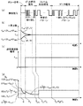
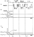
図5は、図1に示す無線通信システム1の動作の一例を説明するための説明図である。図5(a)は無線送信装置2から送信される無線信号を示し、図5(b)はその無線信号が無線受信装置3によって受信された場合にミキサMIXからIFフィルタIFFへ出力されるIF信号の周波数の取り得る範囲(上限と下限)を示し、図5(c)は無線送信装置2におけるFSK変調の周波数偏移量を示し、図5(d)は無線送信装置2におけるIFフィルタIFFで必要となる通過帯域幅BIFを示している。また、図5(a)〜図5(d)の横軸は、自動周波数調整回路AFCによる自動周波数調整の開始からの経過時間tを示している。
FIG. 5 is an explanatory diagram for explaining an example of the operation of the
まず、時間t=0において、無線送信装置2で例えば信号生成部SGに接続された図略の人体センサによって人が検知される等して送信トリガが発生する。このような送信トリガが発生すると、送信制御回路106によって、発振器105と信号生成部101とが起動される。
First, at time t = 0, a transmission trigger is generated when a person is detected by, for example, an unillustrated human body sensor connected to the signal generation unit SG in the
次に、ビット同期信号送信部21は、上述のビット同期符号列、例えば「11001100・・・」を表す信号S1を出力して、送信RF回路TRFから、周波数偏移fDEVのビット同期信号を、無線受信回路31の自動周波数調整回路AFCが自動周波数調整を実行するために必要となる時間として予め設定された調整時間TAFCの間、送信させる。
Next, the bit synchronization
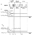
図6は、ビット同期符号列及びデータと、通信速度との関係を説明するための説明図である。図6において、縦軸は無線信号の周波数f、横軸は時間tを示している。図6(a)は、ビット同期符号列「11001100・・・」を送信する際の、無線信号の変調を示している。図6(a)に示すように、ビット同期符号列における4ビット(2n)に対応する期間が、変調周期TMODbに対応している。そうすると、ビット同期信号の通信速度(シンボルレート)は、2/TMODb[bps]となる。 FIG. 6 is an explanatory diagram for explaining the relationship between the bit synchronization code string and data and the communication speed. In FIG. 6, the vertical axis represents the frequency f of the radio signal, and the horizontal axis represents time t. FIG. 6A shows the modulation of the radio signal when transmitting the bit synchronization code string “11001100...”. As shown in FIG. 6A , a period corresponding to 4 bits (2n) in the bit synchronization code string corresponds to the modulation period T MODb . Then, the communication speed (symbol rate) of the bit synchronization signal is 2 / T MODb [bps].
そして、このビット同期信号が無線受信装置3によって受信されると、自動周波数調整回路AFCによる局部発振回路LOの発振周波数の自動調整が開始される(時間t=0)。ここで、無線受信装置3におけるIF周波数の設計値をfIF0、時間tにおけるIF周波数の設計値からのずれの絶対値の最大値を△fIF(t)とすると、自動周波数調整が開始されるとき(t=0)のずれの絶対値の最大値△fIF(0)は、△fTXMAX+△fRXMAXとなる。
When this bit synchronization signal is received by the
すなわち、時間t=0において、IF周波数は、fIF0−(△fTXMAX+△fRXMAX)〜fIF0+(△fTXMAX+△fRXMAX)の範囲となる。このとき、IFフィルタIFFは、この周波数範囲を通過させる必要があるから、時間t=0において必要な通過帯域幅BIFは、式(3)から、下記の式(5)で示される(図5(d))。 That is, at time t = 0, the IF frequency is in the range of f IF0 − (Δf TXMAX + Δf RXMAX ) to f IF0 + (Δf TXMAX + Δf RXMAX ). At this time, since the IF filter IFF needs to pass through this frequency range, the required pass bandwidth B IF at time t = 0 is expressed by the following equation (5) from equation (3) (FIG. 5). 5 (d)).
BIF≧2×{(fMOD/n)+fDEV+△fTXMAX+△fRXMAX} (t=0の場合)・・・(5)
そして、自動周波数調整回路AFCによる自動周波数調整の実行と共に(時間tの経過と共に)、局部発振回路LOから出力される発振信号の周波数が調整されて、自動周波数調整を実行するために必要となる時間である調整時間TAFCの経過後、△fIF(t)は略「0」に収束する。
B IF ≧ 2 × {(f MOD / n) + f DEV + Δf TXMAX + Δf RXMAX } (when t = 0) (5)
Then, along with the execution of the automatic frequency adjustment by the automatic frequency adjustment circuit AFC (with the elapse of time t), the frequency of the oscillation signal output from the local oscillation circuit LO is adjusted, and is necessary for executing the automatic frequency adjustment. after the lapse of the adjustment time T AFC is the time, △ f IF (t) is converged to substantially "0".
ここで、ビット同期信号の符号長は、ビット同期信号を送信するのにかかる時間であるビット送信時間TBが、調整時間TAFCより長くなるように予め設定されている。 Here, the code length of the bit synchronization signal, a bit synchronous signal bit transmission time T B is the time taken to transmit a is previously set to be longer than the adjustment time T AFC.
時間tが、0<t<TAFCの期間において、IFフィルタIFFに要求される通過帯域幅BIFは、下記の式(6)で示される。 When the time t is 0 <t <T AFC , the pass bandwidth B IF required for the IF filter IFF is expressed by the following equation (6).
BIF≧2×{(fMOD/n)+fDEV+△fIF(t)} (0<t<TAFCの場合)・・・(6)
図5(d)においては、n=2の場合の例を示している。
B IF ≧ 2 × {(f MOD / n) + f DEV + Δf IF (t)} (when 0 <t <T AFC ) (6)
FIG. 5D shows an example where n = 2.
その結果、調整時間TAFCが経過した後は、△fIF(t)≒0であるから、時間tが、t≧TAFCの期間において、IFフィルタIFFに要求される通過帯域幅BIFは、下記の式(7)で示される。 As a result, after the adjustment time T AFC elapses, Δf IF (t) ≈0, and therefore, when the time t is t ≧ T AFC , the pass bandwidth B IF required for the IF filter IFF is The following equation (7).
BIF≧2×{(fMOD/n)+fDEV} (t≧TAFCの場合)・・・(7)
図5(d)においては、n=2の場合の例を示している。
B IF ≧ 2 × {(f MOD / n) + f DEV } (when t ≧ T AFC ) (7)
FIG. 5D shows an example where n = 2.
ビット送信時間TBが経過すると、フレーム同期信号送信部22は、上述のビット同期符号列に応じた信号S1を出力して、送信RF回路TRFから、周波数偏移fDEVのフレーム同期信号を送信させる。
When the bit transmission time T B has elapsed, the frame
そして、フレーム同期信号の送信が終わると、データ送信部23は、信号S1を出力して、送信RF回路TRFから、周波数偏移fDEVのデータ信号を送信させる。この場合、データ信号は、例えばスイッチ制御部12にスイッチング素子11のオン、オフを指示する符号列を表しており、一般的にランダムな符号パターンになっている。
When the transmission of the frame synchronization signal ends, the
図6(b)は、データ信号を送信する際の、無線信号の変調を示している。図6(b)においては、説明を容易にするためデータ列として「1010」を送信する例を示している。そうすると、図6(b)に示すように、データ列における2ビットに対応する期間が、変調周期TMODに対応する。そうすると、データ信号の通信速度は、2/TMODとなる。 FIG. 6B shows the modulation of a radio signal when transmitting a data signal. FIG. 6B shows an example in which “1010” is transmitted as a data string for ease of explanation. Then, as shown in FIG. 6B, a period corresponding to 2 bits in the data string corresponds to the modulation period T MOD . Then, the communication speed of the data signal becomes 2 / T MOD .
ここで、ビット同期符号列における4ビット(2n)に対応する期間が変調周期TMODbに対応しており、データ列における2ビットに対応する期間が変調周期TMODに対応しているから、TMODb=n×TMOD となる。そうすると、ビット同期信号の通信速度は、2/TMODb=2/(n×TMOD)となるから、ビット同期信号の実効的な通信速度はデータ信号の1/nとなる。 Here, the period corresponding to 4 bits (2n) in the bit synchronization code string corresponds to the modulation period T MODb , and the period corresponding to 2 bits in the data string corresponds to the modulation period T MOD. MODb = n × T MOD . Then, since the communication speed of the bit synchronization signal is 2 / T MODb = 2 / (n × T MOD ), the effective communication speed of the bit synchronization signal is 1 / n of the data signal.
ここで、ビット同期における変調周波数(=シンボルレート/2)は、1/TMODb=1/(n×TMOD)=fMOD/nとなるから、上記式(6)、式(7)におけるfMOD/nの項が得られる。 Here, the modulation frequency (= symbol rate / 2) in bit synchronization is 1 / T MODb = 1 / (n × T MOD ) = f MOD / n, so in the above formulas (6) and (7) The term f MOD / n is obtained.
なお、nを2以上の整数とすることにより、ビット同期信号の実効的な通信速度を、前記第2符号列の通信速度の1/nに減じる例を示したが、例えば図7に示すように、nを1とし、ビット同期符号列における論理値「1」を示す符号及び論理値「0」を示す符号それぞれについて、一符号の継続時間であるパルス幅Wbを、データ符号列における一符号の継続時間であるパルス幅Wdより長くすることによって(例えばn倍にすることによって)、ビット同期符号列の実効的な通信速度をデータ符号列の通信速度より減じるようにしてもよい。 In addition, although the example in which the effective communication speed of the bit synchronization signal is reduced to 1 / n of the communication speed of the second code string by setting n to an integer of 2 or more is shown, for example, as shown in FIG. N is 1, and for each of the code indicating the logical value “1” and the code indicating the logical value “0” in the bit synchronization code string, the pulse width Wb that is the duration of one code is set as one code in the data code string. The effective communication speed of the bit synchronization code string may be reduced from the communication speed of the data code string by making the pulse width Wd longer than the pulse width Wd (for example, n times).
そして、ビット同期信号やデータ信号を含む無線信号の全体を通じて、これを受信するためにIFフィルタIFFに要求される通過帯域幅BIFは、式(5)及び式(7)から、2×{(fMOD/n)+fDEV+△fTXMAX+△fRXMAX}と、{(fMOD/n)+fDEV}とのうちいずれか大きいほうになる(図5(d)では前者の方が大きい例を示している)。 Then, the pass bandwidth B IF required for the IF filter IFF to receive the entire radio signal including the bit synchronization signal and the data signal is expressed as 2 × {from Equation (5) and Equation (7). (F MOD / n) + f DEV + Δf TXMAX + Δf RXMAX } and {(f MOD / n) + f DEV }, whichever is larger (in FIG. 5D, the former is larger) Example).
一方、図12に示す背景技術では、ビット同期信号における変調周波数が、データ送信時と同じ変調周波数fMODとなるため、IFフィルタ115に要求される通過帯域幅は、式(3)からBIF≧2×(fMOD+fDEVS+△fTXMAX+△fRXMAX)となる。そうすると、IFフィルタIFFに要求される通過帯域幅BIFは、2×{(fMOD/n)+fDEV+△fTXMAX+△fRXMAX}と、{(fMOD/n)+fDEV}とのうちいずれであったとしても、2×(fMOD+fDEVS+△fTXMAX+△fRXMAX)より小さくなる。
On the other hand, in the background art shown in FIG. 12, the modulation frequency in the bit synchronization signal is the same as the modulation frequency f MOD at the time of data transmission, so the pass bandwidth required for
従って、IFフィルタIFFに要求される通過帯域幅BIFを、下記の式(8)を満たす値に設定することが可能となる。 Therefore, the pass bandwidth B IF required for the IF filter IFF can be set to a value satisfying the following equation (8).
BIF<2×(fMOD+fDEVS+△fTXMAX+△fRXMAX) ・・・(8)
そして、IFフィルタIFFに要求される通過帯域幅BIFを、式(8)を満たすように設定することで、式(4)から、図12に示す背景技術よりも、通過帯域幅BIFを狭くして、無線受信回路31の受信感度SSを向上する(小さくする)ことができる。
B IF <2 × (f MOD + f DEVS + Δf TXMAX + Δf RXMAX ) (8)
Then, the pass bandwidth B IF required for the IF filter IFF, by setting so as to satisfy the equation (8), from equation (4), than the background art shown in FIG. 12, the pass band width B IF The reception sensitivity SS of the
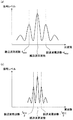
図8は、無線信号のスペクトラム波形を示す図である。図8(a)は、図12に示す背景技術に係るビット同期信号のスペクトラム波形を示し、図8(b)は、図4に示す無線送信装置2(n=2)におけるビット同期信号のスペクトラム波形を示している。 FIG. 8 is a diagram illustrating a spectrum waveform of a radio signal. 8A shows the spectrum waveform of the bit synchronization signal according to the background art shown in FIG. 12, and FIG. 8B shows the spectrum of the bit synchronization signal in the wireless transmission device 2 (n = 2) shown in FIG. The waveform is shown.
図8に示すように、図8(a)に示す背景技術に係るビット同期信号のスペクトラム波形よりも、図8(b)に示す無線送信装置2におけるビット同期信号のスペクトラム波形の方が、無線信号の周波数分布が狭い範囲に収まっており、IFフィルタIFFに要求される通過帯域幅BIFを狭くできることが判る。
As shown in FIG. 8, the spectrum waveform of the bit synchronization signal in the
なお、本実施形態では、無線送信装置2と無線受信装置3とがそれぞれ1台の無線通信システムを示したが、無線送信装置2と無線受信装置3とのいずれか一方もしくは両方が複数台からなる無線通信システムであってもよい。
In the present embodiment, the
以上のように構成された無線通信システム1は、ダミー信号を用いることなく無線受信回路31の受信感度SSを向上する(小さくする)ことができるので、ダミー信号により通信時間が増大するおそれを低減しつつ、無線受信装置におけるIFフィルタの通過帯域幅を狭くすることができる。そして、無線受信装置におけるIFフィルタの通過帯域幅を狭くすることができれば、受信感度を向上したり、隣接チャネル選択度を向上させたりすることが容易となる。
Since the
(第2実施形態)
次に、本発明の第2実施形態に係る無線通信システムについて説明する。第2実施形態に係る無線通信システムは、第1実施形態に係る無線通信システムとは、無線送信装置2の代わりに無線送信装置2aを備える点で異なる。
(Second Embodiment)
Next, a radio communication system according to the second embodiment of the present invention will be described. The wireless communication system according to the second embodiment is different from the wireless communication system according to the first embodiment in that a
図9は、第2実施形態に係る無線送信装置2aの構成の一例を示すブロック図である。図9に示す無線送信装置2aは、図4に示す無線送信装置2とは、送信制御回路TCCaの構成が異なる。
FIG. 9 is a block diagram illustrating an example of a configuration of the
送信制御回路TCCaは、送信制御回路TCCは送信トリガを検出すると、基準発振器OSCを起動すると共に、ビット同期信号送信部21によってビット同期信号を送信させる前に、無変調の信号、すなわち搬送波周波数の信号を、ダミー信号として送信RF回路TRFによって送信させる。そして、送信制御回路TCCaは、ダミー信号の送信後にビット同期信号送信部21によるビット同期信号の送信を開始させる。この場合、送信制御回路TCCaは、無変調送信部の一例に相当している。
When the transmission control circuit TCC detects a transmission trigger, the transmission control circuit TCCa activates the reference oscillator OSC and before the bit synchronization
また、送信制御回路TCCaによるダミー信号の送信にかかる時間をダミー送信時間TDとすると、ビット同期信号送信部21によりビット同期信号の送信が実行される時間とダミー送信時間TDとの合計が、調整時間TAFC以上に設定されている。また、ダミー送信時間TDは、調整時間TAFCより短くされている。
Also, if the dummy transmission time T D to the time taken for the transmission of a dummy signal by the transmission control circuit TCCA, the sum of the time and the dummy transmission time T D of the bit synchronization
その他の構成は図4に示す無線送信装置2と同様であるのでその説明を省略し、以下本実施形態の動作について説明する。図10は、図9に示す無線送信装置2aと、無線受信装置3とを用いた無線通信システムの動作の一例を説明するための説明図である。図10においては、送信制御回路TCCaによるダミー信号の開始時を時間t=0としている。
Since the other configuration is the same as that of the
無変調のダミー信号は、変調によるスペクトラムの拡散がないため、無線受信回路31においてダミー信号を受信するためにIFフィルタIFFに要求される通過帯域幅BIFは、2×(△fTXMAX+△fRXMAX)となる。
Since the unmodulated dummy signal has no spectrum spread due to modulation, the pass bandwidth B IF required for the IF filter IFF to receive the dummy signal in the
これにより、無線送信装置2aは、0≦t<TDの期間においては周波数偏移fDEVをゼロとする。そして、無線受信回路31によってこのダミー信号が受信されると、自動周波数調整回路AFCの動作により、△fIF(t)は徐々に減少する。
Thus, the
そして、ダミー送信時間TDが経過してダミー信号の送信が終了すると、ビット同期信号送信部21によるビット同期信号の送信が開始される。
When the transmission of the dummy signal dummy transmission time T D has elapsed is completed, the transmission of the bit synchronization signal by the bit synchronization
そうすると、無線受信回路31のIFフィルタIFFに要求される通過帯域幅BIFは、式(3)に基づき以下の式(9)〜(12)で与えられる。
Then, the pass bandwidth B IF required for the IF filter IFF of the
BIF≧2×(△fTXMAX+△fRXMAX) (t=0の場合) ・・・(9)
BIF≧2×△fIF(t) (0<t<TDの場合) ・・・(10)
BIF≧2×{(fMOD/2)+fDEV+△fIF(t)} (TD≦t<TD+TBの場合) ・・・(11)
BIF≧2×(fMOD+fDEV) (t≧TD+TBの場合) ・・・(12)
B IF ≧ 2 × (Δf TXMAX + Δf RXMAX ) (when t = 0) (9)
B IF ≧ 2 × △ f IF (t) (0 <t < the case of T D) ··· (10)
B IF ≧ 2 × {(f MOD / 2) + f DEV + Δf IF (t)} (when T D ≦ t <T D + T B ) (11)
B IF ≧ 2 × (f MOD + f DEV ) (when t ≧ T D + T B ) (12)
そして、無線信号の全体を通じて、これを受信するためにIFフィルタIFFに要求される通過帯域幅BIFは、式(9)〜(12)から、2×(△fTXMAX+△fRXMAX)、2×{(fMOD/2)+fDEV+△fIF(TD)}、及び2×(fMOD+fDEV)のうちの最大値になる(図10(d)では、2×(△fTXMAX+△fRXMAX)が最も大きい例を示している)。 Then, the pass bandwidth B IF required for the IF filter IFF to receive the entire wireless signal is expressed by 2 × (Δf TXMAX + Δf RXMAX ), from Equations (9) to (12), 2 × {(f MOD / 2) + f DEV + Δf IF (T D )} and 2 × (f MOD + f DEV ) (2 × (Δf in FIG. 10D ) TXMAX + Δf RXMAX ) is the largest example).
特に、2×(△fTXMAX+△fRXMAX)=2×{(fMOD/2)+fDEV+△fIF(TD)}=2×(fMOD+fDEV)となるように、周波数偏移fDEV、及びダミー送信時間TDを設定すると、IFフィルタIFFの通過帯域幅を最も効率的に利用することができる。 In particular, 2 × (Δf TXMAX + Δf RXMAX ) = 2 × {(f MOD / 2) + f DEV + Δf IF (T D )} = 2 × (f MOD + f DEV ) setting the transfer f DEV, and a dummy transmission time T D, it is possible to use a passband width of the IF filter IFF most efficiently.
これにより、図13に示す背景技術では、少なくとも調整時間TAFCの間、ダミー信号を送信し続ける必要があったが、図10に示す無線送信装置2aは、ダミー送信時間TDを調整時間TAFCより短くできるので、図13に示す背景技術と比べて、通信時間が増大するおそれを低減しつつ、無線受信回路31におけるIFフィルタIFFの通過帯域幅を狭くすることが容易となる。
Thus, in the background art shown in FIG. 13, for at least the adjustment time T AFC, it has been necessary to continue to transmit a dummy signal, a
なお、本実施形態では、無線送信装置2aと無線受信装置3とがそれぞれ1台の無線通信システムを示したが、無線送信装置2aと無線受信装置3とのいずれか一方もしくは両方が複数台からなる無線通信システムであってもよい。
In the present embodiment, the
1 無線通信システム
2,2a 無線送信装置
3 無線受信装置
10 操作ハンドル
21 ビット同期信号送信部
22 フレーム同期信号送信部
23 データ送信部
31 無線受信回路
AFC 自動周波数調整回路
BIF 通過帯域幅
DTC 検波器
fDEV 周波数偏移
fIF0 IF周波数設計値
fMOD 変調周波数
IFA IFアンプ
IFF IFフィルタ
LNA ローノイズアンプ
LO 局部発振回路
MIX ミキサ
OSC 基準発振器
PA パワーアンプ
RANT 受信アンテナ
RBB ベースバンド回路部
RFF RFフィルタ
SG 信号生成部
TAFC 調整時間
TANT 送信アンテナ
TB ビット送信時間
TCC,TCCa 送信制御回路
TD ダミー送信時間
TRF 送信RF回路
Wb,Wd パルス幅
DESCRIPTION OF
Claims (8)
連続する、n(nは整数)個の論理値「1」を示す符号と、連続する、n個の論理値「0」を示す符号とが交互に繰り返される第1符号列と、当該第1符号列の後に続き、通信によって伝えたいデータを含む第2符号列とに対応する信号を生成する信号生成部と、
前記信号生成部によって生成された信号に応じて前記変調を行い、当該変調された無線信号を送信する送信部とを備え、
前記信号生成部は、
前記第1符号列の実効的な通信速度を、前記第2符号列の通信速度より遅くするように、前記第1符号列を生成すること
を特徴とする無線送信装置。 A radio transmission device that modulates a frequency of a radio signal by shifting from a carrier frequency and transmits the modulated radio signal to a radio reception device,
A first code string in which a continuous code indicating n (n is an integer) logical value “1” and a continuous code indicating n logical values “0” are alternately repeated; A signal generator that generates a signal that follows the code string and that corresponds to a second code string that includes data to be transmitted by communication;
A transmitter that performs the modulation according to the signal generated by the signal generator and transmits the modulated radio signal;
The signal generator is
The wireless transmitter according to claim 1, wherein the first code string is generated so that an effective communication speed of the first code string is slower than a communication speed of the second code string.
前記第1送信部によって送信される無線信号を受信する無線受信装置がビット同期をとるためのビット同期符号列であること
を特徴とする請求項1記載の無線送信装置。 The first code string is:
The wireless transmission device according to claim 1, wherein the wireless reception device that receives the wireless signal transmitted by the first transmission unit is a bit synchronization code string for performing bit synchronization.
前記無線受信装置において、受信された無線信号に基づき受信しようとする無線信号の周波数を調整する自動周波数調整を実行するために必要となる時間として予め設定された調整時間以上に設定されていること
を特徴とする請求項1又は2記載の無線送信装置。 The duration of the first code string is:
In the wireless receiving device, the time required for executing automatic frequency adjustment for adjusting the frequency of the wireless signal to be received based on the received wireless signal is set to be equal to or longer than a preset adjustment time. The wireless transmission device according to claim 1 or 2.
前記無変調の無線信号の継続時間と前記第1符号列の継続時間との合計が、前記無線受信装置において、受信された無線信号に基づき受信しようとする無線信号の周波数を調整する自動周波数調整を実行するために必要となる時間として予め設定された調整時間以上に設定されていること
を特徴とする請求項1又は2記載の無線送信装置。 The transmitter further comprises a non-modulated transmitter that transmits a non-modulated radio signal before transmission of the modulated radio signal is started,
Automatic frequency adjustment in which the sum of the duration of the unmodulated radio signal and the duration of the first code string adjusts the frequency of the radio signal to be received based on the received radio signal in the radio receiver The wireless transmission device according to claim 1, wherein the wireless transmission apparatus is set to be equal to or longer than a preset adjustment time as a time required to execute
前記nを2以上の整数とすることにより、前記第1符号列の実効的な通信速度を、前記第2符号列の通信速度の1/nに減じること
を特徴とする請求項1〜4のいずれか1項に記載の無線送信装置。 The signal generator is
5. The effective communication speed of the first code string is reduced to 1 / n of the communication speed of the second code string by setting the n to an integer of 2 or more. The wireless transmission device according to any one of claims.
前記nを1とし、前記第1符号列における論理値「1」を示す符号及び論理値「0」を示す符号それぞれについて、一符号の継続時間を、前記第2符号列における一符号の継続時間より長くすることによって、前記第1符号列の実効的な通信速度を前記第2符号列の通信速度より減じること
を特徴とする請求項1〜4のいずれか1項に記載の無線送信装置。 The signal generator is
For each of the code indicating the logical value “1” and the code indicating the logical value “0” in the first code string, where n is 1, the duration of one code is the duration of one code in the second code string The wireless transmission device according to any one of claims 1 to 4, wherein an effective communication speed of the first code string is reduced from a communication speed of the second code string by making the length longer.
前記無線信号を受信する無線受信装置とを備え、
前記無線受信装置は、
前記無線信号を受信する受信部と、
局部発振周波数の発振信号を生成する局部発振部と、
前記受信部によって取得された受信信号と前記局部発振部によって生成された発振信号とを混合し、前記受信信号を中間周波数に変換して中間周波数信号を生成する混合部と、
前記混合部で生成された中間周波数信号を濾波する中間周波数フィルタと、
前記中間周波数フィルタによって濾波された信号を復調する復調部と、
前記受信部によって受信された前記無線信号に基づいて、前記無線送信装置から送信される無線信号の搬送波周波数の予め設定された設計値からの偏差と前記局部発振周波数の予め設定された設計値からの偏差との差を低減するように前記局部発振周波数を調整する自動周波数調整部とを備え、
前記中間周波数フィルタの通過帯域幅BIFは、前記無線信号の変調周波数をfMOD、前記設定偏移量をfDEV、前記搬送波周波数の設計値からのずれの最大値である搬送波周波数最大偏差を△fTXMAX、前記局部発振周波数の設計値からのずれの最大値である局部発振周波数最大偏差を△fRXMAXとすると、下記の式(1)
BIF < 2×(fMOD+fDEV+△fTXMAX+△fRXMAX) ・・・(1)
を満たすように設定されていること
を特徴とする無線通信システム。 The wireless transmission device according to any one of claims 1 to 6,
A wireless receiving device for receiving the wireless signal;
The wireless receiver is
A receiver for receiving the radio signal;
A local oscillation unit for generating an oscillation signal having a local oscillation frequency;
Mixing a reception signal acquired by the reception unit and an oscillation signal generated by the local oscillation unit, converting the reception signal to an intermediate frequency to generate an intermediate frequency signal; and
An intermediate frequency filter for filtering the intermediate frequency signal generated by the mixing unit;
A demodulator for demodulating the signal filtered by the intermediate frequency filter;
Based on the radio signal received by the receiver, from a preset design value of the carrier frequency of the radio signal transmitted from the radio transmitter and a preset design value of the local oscillation frequency An automatic frequency adjustment unit that adjusts the local oscillation frequency so as to reduce the difference from the deviation of
The pass bandwidth B IF of the intermediate frequency filter has a modulation frequency of the radio signal as f MOD , a set deviation amount as f DEV , and a carrier frequency maximum deviation as a maximum deviation from a design value of the carrier frequency. Δf TXMAX , where the local oscillation frequency maximum deviation that is the maximum deviation from the design value of the local oscillation frequency is Δf RXMAX , the following equation (1)
B IF <2 × (f MOD + f DEV + Δf TXMAX + Δf RXMAX ) (1)
A wireless communication system characterized by being set to satisfy the above.
ユーザの操作指示を受け付ける操作ハンドルと、
負荷への給電経路を開閉するスイッチング素子と、
前記復調部により復調された信号、及び前記操作ハンドルにより受け付けられた操作指示に応じて、前記開閉部を開閉させるスイッチ制御部とを備えること
を特徴とする請求項7記載の無線通信システム。 The wireless receiving device further includes:
An operation handle for accepting user operation instructions;
A switching element that opens and closes a power supply path to the load;
The wireless communication system according to claim 7, further comprising: a switch control unit that opens and closes the opening / closing unit in response to a signal demodulated by the demodulation unit and an operation instruction received by the operation handle.
Priority Applications (1)
| Application Number | Priority Date | Filing Date | Title |
|---|---|---|---|
| JP2008312896A JP5226491B2 (en) | 2008-12-09 | 2008-12-09 | Wireless communication system |
Applications Claiming Priority (1)
| Application Number | Priority Date | Filing Date | Title |
|---|---|---|---|
| JP2008312896A JP5226491B2 (en) | 2008-12-09 | 2008-12-09 | Wireless communication system |
Publications (2)
| Publication Number | Publication Date |
|---|---|
| JP2010141380A true JP2010141380A (en) | 2010-06-24 |
| JP5226491B2 JP5226491B2 (en) | 2013-07-03 |
Family
ID=42351154
Family Applications (1)
| Application Number | Title | Priority Date | Filing Date |
|---|---|---|---|
| JP2008312896A Expired - Fee Related JP5226491B2 (en) | 2008-12-09 | 2008-12-09 | Wireless communication system |
Country Status (1)
| Country | Link |
|---|---|
| JP (1) | JP5226491B2 (en) |
Citations (9)
| Publication number | Priority date | Publication date | Assignee | Title |
|---|---|---|---|---|
| JPH0357325A (en) * | 1989-07-25 | 1991-03-12 | Nec Corp | Earth station communication equipment |
| JPH04268827A (en) * | 1991-02-22 | 1992-09-24 | Sony Corp | Transmitter-receiver |
| JPH07143199A (en) * | 1993-11-19 | 1995-06-02 | Hitachi Ltd | Digital signal demodulator |
| WO2001037505A1 (en) * | 1999-11-12 | 2001-05-25 | Mitsubishi Denki Kabushiki Kaisha | Radio communication terminal capable of specifying burst position accurately and having small frequency error of regenerative carrier wave |
| JP2002198946A (en) * | 2000-12-26 | 2002-07-12 | Toyo Commun Equip Co Ltd | Unique word control method |
| JP2005006092A (en) * | 2003-06-12 | 2005-01-06 | Hitachi Kokusai Electric Inc | Preamble pattern identification method and frequency deviation detection method |
| JP2006014380A (en) * | 2005-09-21 | 2006-01-12 | Hitachi Kokusai Electric Inc | Frequency deviation detection method |
| JP2007027899A (en) * | 2005-07-12 | 2007-02-01 | Mitsubishi Electric Corp | Wireless communication apparatus, wireless communication method, and data structure of communication data |
| JP2008177790A (en) * | 2007-01-17 | 2008-07-31 | Matsushita Electric Works Ltd | Radio transmission system |
-
2008
- 2008-12-09 JP JP2008312896A patent/JP5226491B2/en not_active Expired - Fee Related
Patent Citations (9)
| Publication number | Priority date | Publication date | Assignee | Title |
|---|---|---|---|---|
| JPH0357325A (en) * | 1989-07-25 | 1991-03-12 | Nec Corp | Earth station communication equipment |
| JPH04268827A (en) * | 1991-02-22 | 1992-09-24 | Sony Corp | Transmitter-receiver |
| JPH07143199A (en) * | 1993-11-19 | 1995-06-02 | Hitachi Ltd | Digital signal demodulator |
| WO2001037505A1 (en) * | 1999-11-12 | 2001-05-25 | Mitsubishi Denki Kabushiki Kaisha | Radio communication terminal capable of specifying burst position accurately and having small frequency error of regenerative carrier wave |
| JP2002198946A (en) * | 2000-12-26 | 2002-07-12 | Toyo Commun Equip Co Ltd | Unique word control method |
| JP2005006092A (en) * | 2003-06-12 | 2005-01-06 | Hitachi Kokusai Electric Inc | Preamble pattern identification method and frequency deviation detection method |
| JP2007027899A (en) * | 2005-07-12 | 2007-02-01 | Mitsubishi Electric Corp | Wireless communication apparatus, wireless communication method, and data structure of communication data |
| JP2006014380A (en) * | 2005-09-21 | 2006-01-12 | Hitachi Kokusai Electric Inc | Frequency deviation detection method |
| JP2008177790A (en) * | 2007-01-17 | 2008-07-31 | Matsushita Electric Works Ltd | Radio transmission system |
Also Published As
| Publication number | Publication date |
|---|---|
| JP5226491B2 (en) | 2013-07-03 |
Similar Documents
| Publication | Publication Date | Title |
|---|---|---|
| JP6241613B2 (en) | Electronic device system, terminal device, electronic device system control method, and control program | |
| CA2593422A1 (en) | An apparatus and method for operating a hearing aid | |
| WO2002011382A9 (en) | Low power dual protocol transceiver | |
| JP2008219284A (en) | Transceiver | |
| JP2006173691A (en) | Wireless communication system | |
| TW201605211A (en) | Transmitting apparatus, system and computer-implemented method for applying a phase modulation to a millimeter wave carrier signal with OOK | |
| JP5608140B2 (en) | Transmitting apparatus and transmitting method | |
| JP2010112818A (en) | Receiver for tire condition monitoring apparatus | |
| JP5226491B2 (en) | Wireless communication system | |
| JP5107155B2 (en) | Radio transmission apparatus and radio communication system using the same | |
| CN107889051B (en) | Method and system for determining the distance between a wearable object and a base station | |
| US20170134122A1 (en) | Transmission device, reception device, and communication system and remote operating device each including transmission device and reception device | |
| US7342481B2 (en) | Method and circuit arrangement for wireless data transmission | |
| US7586293B2 (en) | Digital modulation circuit | |
| US20060114969A1 (en) | Data transmission device using SAW filters | |
| US8005442B2 (en) | Wireless network connection system and method using injection locked oscillators | |
| US6914478B2 (en) | Demodulation method and demodulator | |
| KR20060118325A (en) | Wireless communication device and wireless communication method | |
| US20050221777A1 (en) | Radiofrequency data signal reception device and method for implementing the same | |
| US8787489B2 (en) | Wireless communication device | |
| JP4020086B2 (en) | transceiver | |
| JP3806699B2 (en) | Wireless microphone system, receiver, wireless microphone | |
| JP2000278175A (en) | Radio communication unit | |
| JPH07307688A (en) | Frequency hopping communication system and simple radio equipment | |
| JP2006279948A (en) | Method for transmitting data, telecommunications system, apparatus intended to transmit and receive signals, and transmitted pulse sequences |
Legal Events
| Date | Code | Title | Description |
|---|---|---|---|
| A621 | Written request for application examination |
Free format text: JAPANESE INTERMEDIATE CODE: A621 Effective date: 20110921 |
|
| A711 | Notification of change in applicant |
Free format text: JAPANESE INTERMEDIATE CODE: A712 Effective date: 20120111 |
|
| A977 | Report on retrieval |
Free format text: JAPANESE INTERMEDIATE CODE: A971007 Effective date: 20120914 |
|
| A131 | Notification of reasons for refusal |
Free format text: JAPANESE INTERMEDIATE CODE: A131 Effective date: 20120925 |
|
| A521 | Written amendment |
Free format text: JAPANESE INTERMEDIATE CODE: A523 Effective date: 20121107 |
|
| A131 | Notification of reasons for refusal |
Free format text: JAPANESE INTERMEDIATE CODE: A131 Effective date: 20121204 |
|
| A521 | Written amendment |
Free format text: JAPANESE INTERMEDIATE CODE: A523 Effective date: 20130201 |
|
| TRDD | Decision of grant or rejection written | ||
| A01 | Written decision to grant a patent or to grant a registration (utility model) |
Free format text: JAPANESE INTERMEDIATE CODE: A01 Effective date: 20130305 |
|
| A61 | First payment of annual fees (during grant procedure) |
Free format text: JAPANESE INTERMEDIATE CODE: A61 Effective date: 20130314 |
|
| R150 | Certificate of patent or registration of utility model |
Free format text: JAPANESE INTERMEDIATE CODE: R150 |
|
| FPAY | Renewal fee payment (event date is renewal date of database) |
Free format text: PAYMENT UNTIL: 20160322 Year of fee payment: 3 |
|
| LAPS | Cancellation because of no payment of annual fees |