JP2010141382A - Speech transmission device using bone conduction - Google Patents
Speech transmission device using bone conduction Download PDFInfo
- Publication number
- JP2010141382A JP2010141382A JP2008312932A JP2008312932A JP2010141382A JP 2010141382 A JP2010141382 A JP 2010141382A JP 2008312932 A JP2008312932 A JP 2008312932A JP 2008312932 A JP2008312932 A JP 2008312932A JP 2010141382 A JP2010141382 A JP 2010141382A
- Authority
- JP
- Japan
- Prior art keywords
- attached
- signal circuit
- signal
- lead wire
- bone conduction
- Prior art date
- Legal status (The legal status is an assumption and is not a legal conclusion. Google has not performed a legal analysis and makes no representation as to the accuracy of the status listed.)
- Pending
Links
- 210000000988 bone and bone Anatomy 0.000 title claims abstract description 26
- 230000005540 biological transmission Effects 0.000 title abstract description 13
- WABPQHHGFIMREM-UHFFFAOYSA-N lead(0) Chemical compound [Pb] WABPQHHGFIMREM-UHFFFAOYSA-N 0.000 claims abstract description 28
- 239000011368 organic material Substances 0.000 claims abstract description 8
- 230000000052 comparative effect Effects 0.000 description 18
- 238000010586 diagram Methods 0.000 description 7
- 238000002474 experimental method Methods 0.000 description 7
- 239000004020 conductor Substances 0.000 description 5
- 229920001971 elastomer Polymers 0.000 description 5
- 239000000463 material Substances 0.000 description 5
- 229910052751 metal Inorganic materials 0.000 description 5
- 239000002184 metal Substances 0.000 description 5
- XEEYBQQBJWHFJM-UHFFFAOYSA-N Iron Chemical compound [Fe] XEEYBQQBJWHFJM-UHFFFAOYSA-N 0.000 description 4
- 230000000694 effects Effects 0.000 description 4
- 229920005989 resin Polymers 0.000 description 4
- 239000011347 resin Substances 0.000 description 4
- 229910001369 Brass Inorganic materials 0.000 description 2
- RYGMFSIKBFXOCR-UHFFFAOYSA-N Copper Chemical compound [Cu] RYGMFSIKBFXOCR-UHFFFAOYSA-N 0.000 description 2
- PXHVJJICTQNCMI-UHFFFAOYSA-N Nickel Chemical compound [Ni] PXHVJJICTQNCMI-UHFFFAOYSA-N 0.000 description 2
- 239000000853 adhesive Substances 0.000 description 2
- 230000001070 adhesive effect Effects 0.000 description 2
- 229910052782 aluminium Inorganic materials 0.000 description 2
- XAGFODPZIPBFFR-UHFFFAOYSA-N aluminium Chemical compound [Al] XAGFODPZIPBFFR-UHFFFAOYSA-N 0.000 description 2
- 239000010951 brass Substances 0.000 description 2
- 238000001514 detection method Methods 0.000 description 2
- 239000010408 film Substances 0.000 description 2
- 238000007689 inspection Methods 0.000 description 2
- 229910052742 iron Inorganic materials 0.000 description 2
- 238000000034 method Methods 0.000 description 2
- 230000035945 sensitivity Effects 0.000 description 2
- 239000010409 thin film Substances 0.000 description 2
- JOYRKODLDBILNP-UHFFFAOYSA-N Ethyl urethane Chemical compound CCOC(N)=O JOYRKODLDBILNP-UHFFFAOYSA-N 0.000 description 1
- BQCADISMDOOEFD-UHFFFAOYSA-N Silver Chemical compound [Ag] BQCADISMDOOEFD-UHFFFAOYSA-N 0.000 description 1
- 229920006311 Urethane elastomer Polymers 0.000 description 1
- 239000002390 adhesive tape Substances 0.000 description 1
- 239000000919 ceramic Substances 0.000 description 1
- 238000006243 chemical reaction Methods 0.000 description 1
- 239000011231 conductive filler Substances 0.000 description 1
- 229910052802 copper Inorganic materials 0.000 description 1
- 239000010949 copper Substances 0.000 description 1
- 239000011889 copper foil Substances 0.000 description 1
- 238000012937 correction Methods 0.000 description 1
- 229920006332 epoxy adhesive Polymers 0.000 description 1
- 230000005669 field effect Effects 0.000 description 1
- 239000011888 foil Substances 0.000 description 1
- 230000001771 impaired effect Effects 0.000 description 1
- 150000002739 metals Chemical class 0.000 description 1
- 238000012986 modification Methods 0.000 description 1
- 230000004048 modification Effects 0.000 description 1
- 229910052759 nickel Inorganic materials 0.000 description 1
- 239000003973 paint Substances 0.000 description 1
- 230000002093 peripheral effect Effects 0.000 description 1
- 230000010287 polarization Effects 0.000 description 1
- 238000012545 processing Methods 0.000 description 1
- 230000001902 propagating effect Effects 0.000 description 1
- 229910052709 silver Inorganic materials 0.000 description 1
- 239000004332 silver Substances 0.000 description 1
- 238000004544 sputter deposition Methods 0.000 description 1
- 230000002123 temporal effect Effects 0.000 description 1
- 238000012360 testing method Methods 0.000 description 1
- 238000007740 vapor deposition Methods 0.000 description 1
Images

Landscapes
- Details Of Audible-Bandwidth Transducers (AREA)
- Piezo-Electric Transducers For Audible Bands (AREA)
Abstract
Description
本発明は、騒音の激しい環境においても明瞭な音声情報の伝達が可能な、骨伝導を用いた送話装置に関する。 The present invention relates to a transmission device using bone conduction that can transmit clear audio information even in a noisy environment.
騒音の激しい環境においても、明瞭に音声情報を伝えることができる伝達手段として、骨伝導マイクロフォンを用いた送話装置が各種提案されている。骨伝導マイクロフォンは、比較的歴史が古いことから多数の構成が知られているが、特許文献1に記載されているようなバイモルフ型圧電素子を用いるものが広く普及している。
Various transmission devices using a bone conduction microphone have been proposed as a transmission means that can clearly transmit voice information even in a noisy environment. Since the bone conduction microphone has a relatively long history, many configurations are known, but those using a bimorph type piezoelectric element as described in
特許文献1には、イヤーピース本体に内蔵された振動ピックアップの出力電流をリード線によって外部に引出す振動ピックアップ型イヤーマイクロホンにおいて、上記イヤーピース本体の基部に内部空間を形成し、少なくとも該基部の内部空間を導電性物質で閉塞すると共に、該導電性物質に上記リード線のアース側導線を接続したことを特徴とする振動ピックアップ型イヤーマイクロホンが開示されている。
In
また、骨伝導マイクロフォンが周囲の雑音を拾うことで音声情報にノイズが混入し、目的とする音声情報の伝達に支障を来たす場合があり、特許文献2のような、外部騒音の影響を避ける工夫がなされている。 In addition, the bone conduction microphone picks up ambient noise, which may cause noise to be mixed into the voice information and hinder the transmission of the target voice information. Has been made.
特許文献2には、空気、及び人体よりも高い音響インピーダンスを有し、かつ音声振動を伝搬しにくい機械インピーダンスを発揮する重量、剛性を有した材料から成る中空のケースと、該ケースの対向する2つの壁部により夫々支持されることにより密閉空間を挟んで対向配置された薄膜ピエゾフィルム素子から成る2枚の受音板と、を備えた耐騒音マイクにおいて、一方の受音板は、外周縁をケースの一方の壁部により支持されると共に外部に露出した外面を有し、該外面のほぼ全面を受音対象物と接触させた状態で音声振動を受音する音声ピックアップ用の受音板であり、他方の受音板は、他方の壁部の内壁に外面をほぼ全面的に密着支持されたタッチノイズキャンセル用の受音板であることを特徴とする耐騒音マイクが開示されている。 In Patent Document 2, a hollow case made of a material having weight and rigidity that exhibits mechanical impedance that has higher acoustic impedance than air and a human body and that hardly propagates sound vibrations, and the case are opposed to each other. A noise-resistant microphone comprising two sound receiving plates made of thin-film piezo film elements that are opposed to each other across a sealed space by being supported by two wall portions. Sound pickup for a sound pickup having a peripheral surface supported by one wall portion of the case and having an outer surface exposed to the outside, and receiving sound vibration in a state where almost the entire outer surface is in contact with a sound receiving object There is disclosed a noise-resistant microphone, wherein the other sound receiving plate is a touch noise canceling sound receiving plate whose outer surface is substantially closely supported by the inner wall of the other wall portion. Have
骨伝導マイクロフォンは、周囲の騒音に影響されずに話者の音声のみを伝達する目的で使用されるが、周辺環境からの電磁ノイズや、機械的振動によるノイズの影響により、骨伝導マイクロフォンから出力される音声情報に雑音が混入する場合がある。 The bone conduction microphone is used for the purpose of transmitting only the voice of the speaker without being affected by the surrounding noise, but it is output from the bone conduction microphone due to the influence of electromagnetic noise from the surrounding environment and noise due to mechanical vibration. There is a case where noise is mixed in the voice information.
骨伝導マイクロフォンに用いられるバイモルフ型圧電素子などの高いインピーダンスを有するセンサ素子は、周辺環境からの電磁ノイズの影響を受け易く、これら電磁ノイズの音響周波数帯域、例えば交流電源の50〜60Hzの電磁ノイズが雑音として音声情報に混入することがある。 Sensor elements having high impedance, such as bimorph piezoelectric elements used in bone conduction microphones, are easily affected by electromagnetic noise from the surrounding environment, and the acoustic frequency band of these electromagnetic noises, for example, 50-60 Hz electromagnetic noise of an AC power supply May be mixed in the voice information as noise.
一方、骨伝導マイクロフォン本体や、接続された信号ケーブルに周囲の物体などが接触した場合、発生する僅かな摩擦音や衝撃音などの機械的振動が、信号ケーブルを伝わって直接センサ部に届くことによって雑音の原因となる場合がある。 On the other hand, when a surrounding object comes into contact with the bone conduction microphone body or the connected signal cable, mechanical vibrations such as slight frictional noise and impact sound are transmitted directly through the signal cable to the sensor unit. It may cause noise.
特許文献1のような従来の骨伝導マイクロフォンでは、電磁ノイズを低減する方策の一つとして、圧電バイモルフを用いたセンサ部と、センサ部で検出した信号をインピーダンス変換して取り出すFET(電界効果型トランジスタ)や抵抗素子等を用いた変換回路を、金属などの導電材で構成された筐体に一括して納める構造によって電気的にシールドする事が行われるが、このような構成では信号ケーブルなどから骨伝導マイクロフォンの筐体に伝搬する機械的振動によるノイズを低減することはできないという課題がある。
In a conventional bone conduction microphone such as
骨伝導マイクロフォンの機械的振動によるノイズを低減するために、例えば特許文献2に記載されているようなケース(筐体)の重量を大きくする方法があるが、人体と接触して音響振動を検出する骨伝導マイクロフォンにとって、装着時の違和感が増したり、検出感度や音響特性が損なわれるという課題がある。 In order to reduce noise due to mechanical vibration of bone conduction microphones, there is a method of increasing the weight of the case (housing) as described in Patent Document 2, for example, but it detects acoustic vibration by contacting the human body. However, the bone conduction microphone has a problem that the feeling of discomfort at the time of wearing increases, and the detection sensitivity and acoustic characteristics are impaired.
本発明は、かかる従来技術の課題を解決し、機械的振動によるノイズと電磁ノイズを低減することにより、明瞭に音声情報を伝達することができる骨伝導を用いた送話装置の提供を目的とする。 SUMMARY OF THE INVENTION It is an object of the present invention to solve the problems of the prior art and to provide a transmitter using bone conduction that can clearly transmit voice information by reducing noise caused by mechanical vibration and electromagnetic noise. To do.
本発明によれば、少なくとも一つの開口部を有する箱状の筐体と、可撓性を有する有機物材料で被覆したバイモルフ型圧電素子および前記バイモルフ型圧電素子に接続するリード線を備えた音響振動を検知するセンサ部と、前記筐体に取り付けて前記リード線を接続する信号回路部と、前記信号回路部に接続すると共に前記筐体に取り付けて外部機器へ接続し信号伝達を行う信号ケーブルと、前記センサ部の一面を外部に露出させるとともに弾力的に支持するよう前記開口部の底部に取り付ける弾性部材を有し、前記リード線は前記センサ部と前記信号回路部との間に張力を与えないよう取り付け、前記信号ケーブルの前記信号回路部と前記筐体の間は張力を与えないよう取り付けて構成することを特徴とする骨伝導を用いた送話装置が得られる。 According to the present invention, an acoustic vibration including a box-shaped housing having at least one opening, a bimorph piezoelectric element coated with a flexible organic material, and a lead wire connected to the bimorph piezoelectric element. A sensor unit that detects the signal, a signal circuit unit that is attached to the casing and connects the lead wire, a signal cable that is connected to the signal circuit unit and is connected to the casing and connected to an external device to transmit signals. And an elastic member attached to the bottom of the opening so as to expose and elastically support one surface of the sensor unit, and the lead wire applies tension between the sensor unit and the signal circuit unit. There is obtained a transmitting device using bone conduction, characterized in that it is mounted so that no tension is applied between the signal circuit portion of the signal cable and the housing. That.
また本発明によれば、外部に露出する前記センサ部の一面に導電性の薄層を形成し、前記導電性の薄層と前記信号回路部のグランドとを電気的に接続することを特徴とする前記骨伝導を用いた送話装置が得られる。 According to the present invention, a conductive thin layer is formed on one surface of the sensor unit exposed to the outside, and the conductive thin layer is electrically connected to the ground of the signal circuit unit. Thus, a transmitter using the bone conduction is obtained.
更に本発明によれば、前記筐体と前記外部機器に接続する前記信号ケーブルの少なくとも一部に螺旋状の延伸部を備え、前記螺旋状の延伸部に一定の間隔で錘部材を取り付けるよう構成することを特徴とする骨伝導を用いた送話装置が得られる。 Furthermore, according to the present invention, at least a part of the signal cable connected to the casing and the external device is provided with a spiral extension portion, and a weight member is attached to the spiral extension portion at a constant interval. Thus, a speech transmission device using bone conduction can be obtained.
本発明の骨伝導を用いた送話装置では、筐体に対してセンサ部を弾性部材を用いて弾力的に支持するよう取り付けることで、筐体から直接伝わる機械的振動によるノイズを抑制することができる。また、センサ部と信号回路部とを接続するリード線、および信号ケーブルの信号回路部と筐体との間は張力を与えないよう取り付けることで、筐体からの間接的な機械的振動によるノイズの伝搬を抑制することができる。上記構成では筐体の重量を大きくする必要がないため、装着時の違和感や、検出感度など音響特性に影響を与えることがない。 In the transmitting device using bone conduction according to the present invention, the sensor unit is attached to the housing so as to be elastically supported using an elastic member, thereby suppressing noise caused by mechanical vibration directly transmitted from the housing. Can do. In addition, noise caused by indirect mechanical vibrations from the housing by attaching the lead wire connecting the sensor unit and the signal circuit unit and between the signal circuit unit of the signal cable and the housing without applying tension. Can be suppressed. In the above configuration, since it is not necessary to increase the weight of the housing, it does not affect the acoustic characteristics such as a sense of incongruity at the time of mounting and detection sensitivity.
また、外部に露出するセンサ部の一面に導電性の薄層を形成し、導電性の薄層と信号回路部のグランドとを電気的に接続することで、センサ部の表面が人体表皮と接触して信号回路部のグランドと導通することにより、各部間の電位差を一様に低下させることができるため、効果的な電気的シールドが行われ、周辺環境からの電磁ノイズの影響を抑制することができる。 In addition, a thin conductive layer is formed on one surface of the sensor unit exposed to the outside, and the conductive thin layer is electrically connected to the ground of the signal circuit unit so that the surface of the sensor unit is in contact with the human skin. By connecting to the ground of the signal circuit section, the potential difference between each section can be reduced uniformly, so that effective electrical shielding is performed and the influence of electromagnetic noise from the surrounding environment is suppressed. Can do.
更に、信号ケーブルの少なくとも一部を螺旋状とし、一定の間隔で錘部材を取り付けることにより、螺旋状構造が持つバネ性(コンプライアンス)と錘部材の重量によって、信号ケーブルそのものを機械的なローパスフィルタとして構成することで、機械的振動によるノイズが抑制される。 Furthermore, by making at least a part of the signal cable into a spiral shape and attaching weight members at regular intervals, the signal cable itself is mechanically low-pass filtered by the spring property (compliance) of the spiral structure and the weight of the weight member. As a result, noise due to mechanical vibration is suppressed.
本発明によれば、機械的振動によるノイズと電磁ノイズを低減することにより、明瞭に音声情報を伝達することができる骨伝導を用いた送話装置の提供が可能となる。 According to the present invention, it is possible to provide a speech transmission device using bone conduction that can clearly transmit voice information by reducing noise caused by mechanical vibration and electromagnetic noise.
以下、本発明の実施の形態について、図面を参照して説明する。 Embodiments of the present invention will be described below with reference to the drawings.
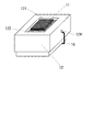
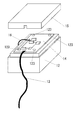
図1は、本発明による送話装置の構成を示す外観斜視図であり、図2は図1の送話装置の裏面側の構成を示す外観斜視図である。 FIG. 1 is an external perspective view showing the configuration of the transmitter according to the present invention, and FIG. 2 is an external perspective view showing the configuration of the back side of the transmitter of FIG.
本発明による送話装置の構成は、開口部121を有する箱状の筐体12と、可撓性を有する有機物材料で被覆した図示しないバイモルフ型圧電素子およびバイモルフ型圧電素子に接続するリード線16からなるセンサ部11と、図1の筐体12の裏面側に設け、リード線16を接続する信号回路基板14と、信号回路基板14に接続して図示しない外部機器への信号伝達を行う信号ケーブル13と、センサ部11の一面を外部に露出させるとともに弾力的に支持するよう開口部121の底面に取り付ける弾性部材122を有する。
The structure of the transmitter according to the present invention includes a box-
筐体12の材質は、電磁ノイズおよび機械的振動によるノイズに対して有効な導電性と剛性を有するものとして、鉄や真鍮、アルミニウムなどの金属が好適である。また、特性が適すれば導電フィラーを添加した樹脂や、表面に導電皮膜を設けた樹脂を用いることもできる。
The material of the
弾性部材122は、筐体12からセンサ部11に伝わる機械的振動を減衰させる効果の高い可撓性を有する材質が望ましく、例えばゴムや軟質樹脂などが適している。
The
リード線16は、センサ部11と信号回路基板14との間に張力を与えないよう筐体12のリード線導出部124を経て取り付け、信号ケーブル13の信号回路基板14と筐体12の間も同様に張力を与えないよう取り付ける。
The
また、センサ部11の外部に露出する一面に導電性の薄層を形成し、リード線16を経て信号回路基板14のグランドと導通させると共に、信号回路基板14を筐体12に取り付ける基板固定ねじ123は、信号回路基板14のグランドと筐体12を導通させることが好ましい。
Further, a conductive thin layer is formed on one surface exposed to the outside of the
導電性の薄層は、銅やアルミニウム、ニッケル等の金属箔を貼り付ける構成が簡便であるが、それらの金属を蒸着やスパッタリングによって薄膜として形成することもできる。 The conductive thin layer has a simple structure in which a metal foil such as copper, aluminum, or nickel is attached, but these metals can be formed as a thin film by vapor deposition or sputtering.
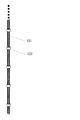
図3は、本発明による送話装置の螺旋状の信号ケーブルを示す概略図である。バネ性を有する螺旋状の信号ケーブル131に一定の間隔で錘部材132を取り付けたものであり、錘部材132の重量や取り付け位置は螺旋状の信号ケーブル131によって異なるため、信号ケーブル131が機械的なローパスフィルタとして構成されるよう、実験等により最適な重量や位置を決定することが好ましい。
FIG. 3 is a schematic view showing a spiral signal cable of the transmitter according to the present invention. The
図4は、本発明による送話装置のセンサ部分の構成を示す概略斜視図である。リード線110およびグランド側リード線112を取り付けたバイモルフ型圧電素子111を、可撓性を有する有機物材料113で被覆し、その上下の面に導電性の薄層114を設ける構成である。上下面の導電性の薄層114は、導線または導電性塗料で形成した導体パターンによって互いに導通すると共に、グランド側リード線112に接続される。
FIG. 4 is a schematic perspective view showing the configuration of the sensor portion of the transmitter according to the present invention. The bimorph
可撓性を有する有機物材料113としては、ウレタン等の樹脂や、各種のゴム系材料を用いることができる。
As the
以下に実施例を用いて、本発明の実施の形態を詳述する。 Hereinafter, embodiments of the present invention will be described in detail using examples.
(実施例1)
本実施例による送話装置のセンサ部11は、図4に示すような構成であり、両面に銀電極を焼き付けて分極処理した10mm×4.5mm×0.25mmの圧電セラミック2枚の間に、10mm×4.5mm×0.05mmの真鍮板をエポキシ系接着剤を用いてサンドイッチ状に一体化して13mm×7mm×3mmの寸法としたバイモルフ型圧電素子111に、直径0.2mmの縒り線を半田付けしてリード線110およびグランド側リード線112とし、硬度90のウレタンゴムを有機物材料113として被覆し、上下面に配する導電性の薄層114は3μm厚の銅箔を粘着テープで貼り付け、リード線を端部に半田付けしてグランド側リード線112に接続したものである。
Example 1
The
本実施例は図1および図2に示すような構成であり、筐体12の材質は鉄製で、外形は30mm×20mm×8mmであり、人体に装着することと、剛性を確保すること双方の理由により、各々のコーナー部分は角が落とされ全体的に丸みを帯びた形状とした。
This embodiment is configured as shown in FIG. 1 and FIG. 2, and the
筐体12に設けた開放部は、20mm×10mm×5mmの窪み形状であり、弾性部材122として19mm×9mm×2mmの生ゴム板を筐体12の開放部の窪みの底にゴム系の接着剤で固定し、その上に上記のセンサ部11を開放部側面に接触させないよう位置決めしてゴム系接着剤で固定した。
The opening portion provided in the
筐体12の側面にリード線導出部124となる横穴を設け、リード線16を通して、筐体12の裏面に取り付けた信号回路基板14との間に張力を与えないよう接続した。この信号回路基板14のグランドは、筐体12に取り付ける基板固定ねじ123によって導通させた。
A lateral hole serving as a lead wire lead-out
信号回路基板14に、外部機器への信号伝達を行う信号ケーブル13を接続した。信号ケーブル13は全長50mmで、その先端に直径2.5mmのオーディオ用ミニプラグを取り付けた。
A
(実施例2)
上記実施例1の構成から、信号ケーブル13を交換したものを実施例2とした。信号ケーブル13は、詳しくは図3に示すような螺旋状の延伸部を有し、螺旋の外径は4mmである。延伸部には20mm間隔で重量約1gのビーズ状の金属リングからなる錘部材132を取り付けた。そのほかの構成は実施例1と同様である。
(Example 2)
Example 2 was obtained by replacing the
(比較例1)
上記実施例2の送話装置の構成から、筐体12、裏蓋15、および弾性部材122を除いた、センサ部11が単独で露出しているものを比較例1とした。実施例2との比較実験においては、手でセンサ部11を保持して空中に信号ケーブル13を垂らし、信号ケーブル13のセンサ部11から10cm以上離れた部分を指で擦ることによって機械的振動によるノイズを入力した。
(Comparative Example 1)
Comparative Example 1 is the
(比較例2)
上記実施例2の送話装置の構成から、センサ部11の表面に導電性の薄層114を設けないものを比較例2とした。実施例2との比較実験においては、センサ部11を側頭部に押しつけた状態で、通常の安定器による蛍光灯スタンドを点灯させながら頭部に接近させることによって電磁ノイズを入力した。
(Comparative Example 2)
Comparative Example 2 in which the conductive
(比較実験)
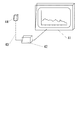
本発明による実施例の効果を確認するため、図5のような構成で比較例1および比較例2の比較実験を行った。図5は、本発明の比較実験におけるノイズ検査システムを示す概略図である。骨伝導マイクロフォンを含む送話部44に、信号ケーブル43を介してマイクアンプ42を接続した。マイクアンプ42から出力された信号の周波数成分をFFT(Fast Fourier Transform:高速フーリエ変換)アナライザ41で解析を行った。FFTアナライザ41が解析する周波数領域は、人間の可聴域とされる20Hz〜20kHzとした。FFTアナライザ41には、送話部44が検知するあらゆる機械的振動と、混入する電磁ノイズとの総和が、周波数に対する利得として表示される。
(Comparative experiment)
In order to confirm the effect of the example according to the present invention, comparative experiments of Comparative Example 1 and Comparative Example 2 were performed with the configuration as shown in FIG. FIG. 5 is a schematic diagram showing a noise inspection system in a comparative experiment of the present invention. A
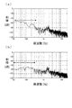
図6は本発明における筐体の影響を比較する図であり、図6(a)は筐体がない場合、すなわち比較例1を示し、図6(b)は筐体がある場合、すなわち実施例2を示す。 6A and 6B are diagrams for comparing the influence of the casing in the present invention. FIG. 6A shows the case where there is no casing, that is, Comparative Example 1, and FIG. Example 2 is shown.
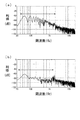
図7は本発明におけるセンサ部の導電化の影響を比較する図であり、図7(a)はセンサ部を導電化しない場合、すなわち比較例2を示し、図7(b)はセンサ部を導電化した場合、すなわち実施例2を示す。 FIG. 7 is a diagram for comparing the influence of the conductivity of the sensor unit in the present invention. FIG. 7A shows a case where the sensor unit is not made conductive, that is, Comparative Example 2, and FIG. Example 2 is shown when conducting.
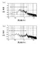
図8は本発明における信号ケーブルに取り付ける錘部材の影響を比較する図であり、図8(a)は通常の信号ケーブルを用いた場合、すなわち実施例1を示し、図8(b)は螺旋状の延伸部に錘部材を取り付けた信号ケーブルを用いた場合、すなわち実施例2を示す。ノイズの入力方法は比較例1と同様である。 FIG. 8 is a diagram for comparing the influence of a weight member attached to a signal cable in the present invention. FIG. 8A shows a case where a normal signal cable is used, that is, Example 1, and FIG. Example 2 shows a case where a signal cable having a weight member attached to an elongated portion is used. The method for inputting noise is the same as in Comparative Example 1.
本発明による実施例2を比較例1および比較例2と比較すると、実施例2の方のノイズレベルが低く、特に図6および図7の図中矢印で示した低周波側の周波数範囲にてその差が顕著であった。 Comparing Example 2 according to the present invention with Comparative Example 1 and Comparative Example 2, the noise level of Example 2 is lower, especially in the frequency range on the low frequency side indicated by the arrows in FIGS. 6 and 7. The difference was remarkable.
また、本発明による実施例1の構成でも、比較例1および比較例2よりも低周波側のノイズを低減する効果が認められるが、実施例2の構成では更にノイズ低減の効果が高まった。 In addition, the configuration of Example 1 according to the present invention has an effect of reducing noise on the lower frequency side than Comparative Example 1 and Comparative Example 2, but the configuration of Example 2 further increases the noise reduction effect.
従って、本発明の構成により、機械的振動によるノイズと電磁ノイズを低減することが可能となり、骨伝導を用いた送話装置において明瞭に音声情報を伝達することができる。 Therefore, according to the configuration of the present invention, it is possible to reduce noise due to mechanical vibration and electromagnetic noise, and voice information can be clearly transmitted in a transmitter using bone conduction.
以上、実施例を用いて本発明の実施の形態を説明したが、本発明はこれら実施例に限定されるものではなく、本発明の要旨を逸脱しない範囲で、材質や構成の変更があっても本発明に含まれる。すなわち、当業者であれば当然なしえるであろう各種変形や修正もまた、本発明に含まれる。 As mentioned above, although embodiment of this invention was described using the Example, this invention is not limited to these Examples, There exists a change of a material and a structure in the range which does not deviate from the summary of this invention. Are also included in the present invention. That is, various modifications and corrections that can naturally be made by those skilled in the art are also included in the present invention.
11 センサ部
12 筐体
13、43 信号ケーブル
14 信号回路基板
15 裏蓋
16、110 リード線
111 バイモルフ型圧電素子
112 グランド側リード線
113 有機物材料
114 導電性の薄層
121 開口部
122 弾性部材
123 基板固定ねじ
124 リード線導出部
131 螺旋状信号ケーブル
132 錘部材
41 FFTアナライザ
42 マイクアンプ
44 送話部
DESCRIPTION OF
Claims (3)
可撓性を有する有機物材料で被覆したバイモルフ型圧電素子および前記バイモルフ型圧電素子に接続するリード線を備えた音響振動を検知するセンサ部と、
前記筐体に取り付けて前記リード線を接続する信号回路部と、
前記信号回路部に接続すると共に前記筐体に取り付けて外部機器へ接続し信号伝達を行う信号ケーブルと、
前記センサ部の一面を外部に露出させるとともに弾力的に支持するよう前記開口部の底部に取り付ける弾性部材を有し、
前記リード線は前記センサ部と前記信号回路部との間に張力を与えないよう取り付け、
前記信号ケーブルの前記信号回路部と前記筐体の間は張力を与えないよう取り付けて構成することを特徴とする骨伝導を用いた送話装置。 A box-shaped housing having at least one opening;
A sensor unit for detecting acoustic vibration comprising a bimorph type piezoelectric element coated with a flexible organic material and a lead wire connected to the bimorph type piezoelectric element;
A signal circuit unit that is attached to the housing and connects the lead wires;
A signal cable that connects to the signal circuit unit and attaches to the housing to connect to an external device and transmits a signal,
An elastic member attached to the bottom of the opening so as to be elastically supported while exposing one surface of the sensor unit;
The lead wire is attached not to give tension between the sensor part and the signal circuit part,
A transmitting device using bone conduction, wherein the signal circuit portion of the signal cable and the casing are attached so as not to apply tension.
Priority Applications (1)
| Application Number | Priority Date | Filing Date | Title |
|---|---|---|---|
| JP2008312932A JP2010141382A (en) | 2008-12-09 | 2008-12-09 | Speech transmission device using bone conduction |
Applications Claiming Priority (1)
| Application Number | Priority Date | Filing Date | Title |
|---|---|---|---|
| JP2008312932A JP2010141382A (en) | 2008-12-09 | 2008-12-09 | Speech transmission device using bone conduction |
Publications (1)
| Publication Number | Publication Date |
|---|---|
| JP2010141382A true JP2010141382A (en) | 2010-06-24 |
Family
ID=42351156
Family Applications (1)
| Application Number | Title | Priority Date | Filing Date |
|---|---|---|---|
| JP2008312932A Pending JP2010141382A (en) | 2008-12-09 | 2008-12-09 | Speech transmission device using bone conduction |
Country Status (1)
| Country | Link |
|---|---|
| JP (1) | JP2010141382A (en) |
Cited By (1)
| Publication number | Priority date | Publication date | Assignee | Title |
|---|---|---|---|---|
| CN109348387A (en) * | 2018-09-05 | 2019-02-15 | 温慎洁 | A bone conduction sound transmission device |
-
2008
- 2008-12-09 JP JP2008312932A patent/JP2010141382A/en active Pending
Cited By (2)
| Publication number | Priority date | Publication date | Assignee | Title |
|---|---|---|---|---|
| CN109348387A (en) * | 2018-09-05 | 2019-02-15 | 温慎洁 | A bone conduction sound transmission device |
| WO2020048371A1 (en) * | 2018-09-05 | 2020-03-12 | 温慎洁 | Bone-conduction sound transmission device |
Similar Documents
| Publication | Publication Date | Title |
|---|---|---|
| US9967643B2 (en) | Earphone | |
| JP7149585B2 (en) | Electroacoustic transducer and electroacoustic transducer | |
| WO2017187710A1 (en) | Vibration waveform sensor and pulse wave detector | |
| JP4851331B2 (en) | Microphone component and manufacturing method thereof | |
| JP2004177818A (en) | Piezoelectric transducer for stringed instrument, bridge for stringed instrument, and stringed instrument | |
| JP5036412B2 (en) | Piezoelectric sensors and electronic stringed instruments | |
| KR880000963B1 (en) | Electret microphone shield | |
| EP2876896B1 (en) | Audio transducer with electrostatic discharge protection | |
| JP2002262377A (en) | Bone conduction pickup element and its unit | |
| JP6069237B2 (en) | Electronics | |
| JP6348365B2 (en) | Mounting structure of electro-acoustic conversion device | |
| EA002963B1 (en) | Sound pickup sensor | |
| JP2011182000A (en) | Body-conducted sound sensor | |
| JP2010141382A (en) | Speech transmission device using bone conduction | |
| JP4002520B2 (en) | Electrostatic microphone transducer | |
| JP2504116B2 (en) | Vibration sensor | |
| JP5036413B2 (en) | Electrode integrated shield terminal | |
| US20070269060A1 (en) | Structure and Method of Condenser Microphone Device for Skin-Contact Usage | |
| WO2015199138A1 (en) | Electronic apparatus | |
| US20260007383A1 (en) | Biological sound sensor | |
| JP6363352B2 (en) | Electronics | |
| JP2010273242A (en) | Unidirectional condenser microphone unit | |
| CN203618122U (en) | Radio device | |
| JPH0697184B2 (en) | Electret-condenser type vibration sensor | |
| JP2504115B2 (en) | Vibration sensor |