JP2010141468A - Onboard acoustic apparatus - Google Patents
Onboard acoustic apparatus Download PDFInfo
- Publication number
- JP2010141468A JP2010141468A JP2008314110A JP2008314110A JP2010141468A JP 2010141468 A JP2010141468 A JP 2010141468A JP 2008314110 A JP2008314110 A JP 2008314110A JP 2008314110 A JP2008314110 A JP 2008314110A JP 2010141468 A JP2010141468 A JP 2010141468A
- Authority
- JP
- Japan
- Prior art keywords
- vehicle
- sound
- microphone
- noise
- signal
- Prior art date
- Legal status (The legal status is an assumption and is not a legal conclusion. Google has not performed a legal analysis and makes no representation as to the accuracy of the status listed.)
- Withdrawn
Links
- 230000005236 sound signal Effects 0.000 claims abstract description 47
- 238000012545 processing Methods 0.000 claims abstract description 37
- 230000003321 amplification Effects 0.000 claims description 45
- 238000003199 nucleic acid amplification method Methods 0.000 claims description 45
- 238000000034 method Methods 0.000 description 29
- 230000008569 process Effects 0.000 description 27
- 238000012986 modification Methods 0.000 description 18
- 230000004048 modification Effects 0.000 description 18
- 238000010586 diagram Methods 0.000 description 10
- 238000004364 calculation method Methods 0.000 description 6
- 238000004590 computer program Methods 0.000 description 6
- 238000009434 installation Methods 0.000 description 4
- 238000001228 spectrum Methods 0.000 description 4
- 239000003990 capacitor Substances 0.000 description 3
- 230000006870 function Effects 0.000 description 3
- 238000012546 transfer Methods 0.000 description 3
- 238000004458 analytical method Methods 0.000 description 2
- 238000009826 distribution Methods 0.000 description 2
- 238000005516 engineering process Methods 0.000 description 2
- 239000004973 liquid crystal related substance Substances 0.000 description 2
- 230000001052 transient effect Effects 0.000 description 2
- 238000013459 approach Methods 0.000 description 1
- 238000004422 calculation algorithm Methods 0.000 description 1
- 238000012937 correction Methods 0.000 description 1
- 230000007423 decrease Effects 0.000 description 1
- 238000001514 detection method Methods 0.000 description 1
- 239000000203 mixture Substances 0.000 description 1
- 230000009467 reduction Effects 0.000 description 1
- 230000004044 response Effects 0.000 description 1
- 230000011664 signaling Effects 0.000 description 1
Images








Landscapes
- Circuit For Audible Band Transducer (AREA)
- Fittings On The Vehicle Exterior For Carrying Loads, And Devices For Holding Or Mounting Articles (AREA)
Abstract
Description
本発明は、車載音響装置に関する。 The present invention relates to an on-vehicle acoustic device.
車載オーディオ機器の分野では、車両周辺の騒音に応じて音量の調整等を行う技術が提案されている。例えば、特許文献1には、車両用音声認識技術であって、レーザーレーダーで近接車両を検知すると運転者方向にマイクロホンの指向性を向ける技術が開示されている。また、特許文献2には、前席用スピーカと後席用スピーカのうち付近の騒音が大きい方のスピーカの音量を上げる技術が開示されている。また、特許文献3には、検出した車内騒音のレベルと、車速信号から受聴者が感じる騒音レベルを推定し、この走行騒音レベルが大きくなるほど再生オーディオ信号の音量およびダイナミックレンジが大きくなるようにする技術が開示されている。
車内でオーディオを聞いている際、車両の周辺で騒音が発生すると、騒音が発生している方向の音声が聞こえにくくなり、且つ聞こえ方に偏りが発生する。また、音量を上げても全てのスピーカの音量が上がるため、音の聞こえ方のバランスは偏ったままとなる。特に、各座席に人が座っている際に、音が聞こえにくい人の音量操作により他の人の音の聞こえ方が変わるので、音の偏りが生じる。本発明は、このような課題に鑑みてなされたものであり、車両周辺で発生した音の影響を抑える車載音響装置を提供することを課題とする。 When listening to audio in the vehicle, if noise is generated around the vehicle, it is difficult to hear the sound in the direction in which the noise is generated, and the way of hearing is biased. Further, even if the volume is increased, the volume of all speakers is increased, so that the balance of how the sound is heard remains biased. In particular, when a person is seated in each seat, the sound volume of a person who is difficult to hear sounds changes the way other people hear the sound, resulting in a sound bias. This invention is made | formed in view of such a subject, and makes it a subject to provide the vehicle-mounted audio apparatus which suppresses the influence of the sound which generate | occur | produced around the vehicle.
本発明は、上記課題を解決するため、予め用意した各方向からの音の音響モデルと実測した音とに基づき、車両周辺の音の到来方向に応じた各スピーカの音のバランスの調整を行う。 In order to solve the above-described problems, the present invention adjusts the sound balance of each speaker according to the arrival direction of the sound around the vehicle based on the acoustic model of the sound from each direction prepared in advance and the actually measured sound. .
詳細には、車内の複数箇所に設置された各スピーカへ音声信号を出力する車載音響装置であって、音源となる音声信号が入力されると、該音声信号を増幅して前記各スピーカへ出力する増幅処理手段と、車両に到来する車両周辺の音のモデルであって、音の到来方向に応じて用意された複数のモデルで構成される第一の音響モデルを記憶する記憶手段と、車両周辺の音を検知するマイクロホンからの信号と、前記記憶手段が記憶する前記第一の音響モデルとに基づく、該車両周辺の音の到来方向に応じた制御を前記増幅処理手段へ行う音量調整手段と、を備える。 Specifically, it is an in-vehicle acoustic device that outputs a sound signal to each speaker installed in a plurality of locations in the vehicle, and when a sound signal serving as a sound source is input, the sound signal is amplified and output to each speaker. Amplifying processing means for storing, a storage means for storing a first acoustic model composed of a plurality of models prepared according to the direction of sound arrival, which is a model of sound around the vehicle arriving at the vehicle, and the vehicle Volume adjustment means for performing control according to the direction of arrival of sound around the vehicle to the amplification processing means based on a signal from a microphone that detects surrounding sounds and the first acoustic model stored in the storage means And comprising.
ここで、上記車載音響装置が音声信号を出力する各スピーカは、車内の複数箇所に設置されているため、各スピーカの音量のバランスを調整することで乗員が感じる音の中心点を変えることが可能である。上記増幅処理手段は、各スピーカへ出力する音声信号の増幅率をスピーカ毎に調整することが可能であり、それらのバランスは増幅処理手段により適宜調整される。 Here, each speaker from which the in-vehicle acoustic device outputs an audio signal is installed at a plurality of locations in the vehicle. Therefore, by adjusting the volume balance of each speaker, the center point of the sound felt by the passenger can be changed. Is possible. The amplification processing means can adjust the amplification factor of the audio signal output to each speaker for each speaker, and the balance thereof is appropriately adjusted by the amplification processing means.
ところで、外部騒音が到来した場合、到来方向に近い方から聞こえていたスピーカ音は騒音にかき消されて聞こえにくくなるため、乗員が感じる音の中心点がずれる。このため
、外部騒音が到来したら到来方向にあるスピーカの音量が他よりも大きくなるように各スピーカ間の音量のバランスを調整する必要がある。上記車載音響装置では、車両周辺で発生した音の到来方向にあるスピーカの音量が他よりも大きくなるようにするため、音の到来方向に応じて予め用意した複数のモデルと、実測した音の信号とを比較し、この比較結果に応じた増幅処理手段への制御を施すことにより、音のバランス調整を行う。
By the way, when external noise arrives, the speaker sound heard from the direction close to the arrival direction is erased by the noise and becomes difficult to hear, so that the center point of the sound felt by the occupant shifts. For this reason, it is necessary to adjust the volume balance between the speakers so that the volume of the speakers in the direction of arrival becomes higher than the other when external noise arrives. In the on-vehicle acoustic device, in order to make the volume of the speaker in the direction of arrival of the sound generated around the vehicle larger than others, a plurality of models prepared in advance according to the direction of arrival of the sound and the measured sound The balance of the sound is adjusted by comparing the signal and controlling the amplification processing means according to the comparison result.
以上のように構成される車載音響装置によれば、車両周辺で発生した音の影響を抑えることが可能となる。 According to the vehicle-mounted acoustic device configured as described above, it is possible to suppress the influence of sound generated around the vehicle.
また、前記音量調整手段は、前記マイクロホンからの信号と前記第一の音響モデルとの尤度をモデル毎に算出し、各モデルに規定されている音の到来方向に対応する位置に設置されたスピーカの音量が、算出した該尤度に応じた音量になるように前記増幅処理手段を制御してもよい。これによれば、数値的なパラメータである尤度に応じた音量の調整が可能となるため、音の到来方向に応じたスピーカの音量の調整が精細に行われる。このため、車両周辺で発生した音の影響をより適切に抑えることが可能である。 Further, the sound volume adjusting means calculates the likelihood of the signal from the microphone and the first acoustic model for each model, and is installed at a position corresponding to the direction of arrival of the sound defined in each model. The amplification processing means may be controlled so that the volume of the speaker becomes a volume corresponding to the calculated likelihood. According to this, since the volume can be adjusted according to the likelihood that is a numerical parameter, the volume of the speaker according to the sound arrival direction is finely adjusted. For this reason, it is possible to suppress the influence of the sound generated around the vehicle more appropriately.
また、前記記憶手段は、車両に到来する車両周辺の音のモデルであって、音の種類に応じて用意された複数のモデルで構成される第二の音響モデルを更に記憶し、前記音量調整手段は、前記マイクロホンからの信号と前記第二の音響モデルとに基づいて該車両周辺の音の種類を判別し、該音の種類に応じた前記増幅処理手段の制御を行うものであってもよい。このような構成にしておけば、各スピーカの音のバランスを車両周辺の音の種類に応じたものにすることが可能であり、車両周辺で発生した音の影響を抑える際の処理内容を適宜設定することが可能である。 Further, the storage means further stores a second acoustic model that is a model of sounds around the vehicle that arrives at the vehicle, and includes a plurality of models prepared according to the type of sound, and the volume adjustment The means may determine the type of sound around the vehicle based on the signal from the microphone and the second acoustic model, and control the amplification processing means according to the type of sound. Good. With such a configuration, it is possible to balance the sound of each speaker according to the type of sound around the vehicle, and the processing content when suppressing the influence of the sound generated around the vehicle is appropriately determined. It is possible to set.
車両周辺で発生した音の影響を抑えることが可能となる。 It is possible to suppress the influence of sound generated around the vehicle.
以下、この発明を実施するための最良の形態を例示的に説明する。以下に示す実施形態は例示であり、本発明はこれらに限定されない。 Hereinafter, the best mode for carrying out the present invention will be described by way of example. Embodiment shown below is an illustration and this invention is not limited to these.
<システムの構成>
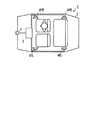
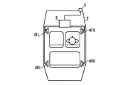
図1は、本発明の一実施形態に係るオーディオシステム1を搭載した車両2を示す図である。図1に示すように、オーディオシステム1は、メインユニット3(本発明でいう、車載音響装置に相当する)、スピーカ4(FR,FL,RR,RL)、及びマイク5(本発明でいう、マイクロホンに相当する)で構成されている。メインユニット3は、図示しない操作パネルを正面に有しており、運転席に着座しているドライバが操作しやすい位置に配置されている。メインユニット3には、車両2の正面に取り付けられたマイク5、及び車室内に配置された4つのスピーカ4が接続されている。車両2は、乗車可能な人数が4〜5名の普通自動車であり、4つのスピーカ4が右前の座席付近(スピーカ4FR)、左前の座席付近(スピーカ4FL)、右後の座席付近(スピーカ4RR)、左後の座席付近(スピーカ4RL)にそれぞれ取り付けられている。
<System configuration>
FIG. 1 is a diagram showing a
各スピーカ4は、車室内の内装パネルやリアパーセルボード等に配置されており、メインユニット3から出力される電気音声信号を音波に変換する。スピーカ4は、周知のように、アンプから出力される電気音声信号の強度や周波数によって振幅や周期を変えるコイルが内蔵されており、コイルに連結されたコーンがコイルの動きを受けて振動することにより、電気信号を音波に変換する。
Each
マイク5は、車両2正面のフロントバンパー付近に配置されており、車両2の周辺の音
を電気信号に変換する。マイク5は、周知のように、音波を電気信号に変換するコンデンサが内蔵されており、コンデンサが音波の振動で電気音声信号を生成する。なお、マイク5は、メインユニット3から供給される電力をコンデンサの両極に印加し、音波によって生ずる両極間の電位変動によって音波を電気信号に変換する。
The
図2は、オーディオシステム1のシステム構成図である。図2に示すように、オーディオシステム1のメインユニット3は、アンプユニット6(本発明でいう、増幅処理手段に相当する)、セレクタ7、ソースユニット8(本発明でいう、音源に相当する)、制御ユニット9(本発明でいう、音量調整手段に相当する)、及び操作スイッチパネル10で構成されており、スピーカ4がアンプユニット6に接続されると共に、マイク5が制御ユニット9に接続されている。
FIG. 2 is a system configuration diagram of the audio system 1. As shown in FIG. 2, the
アンプユニット6は、4つのアンプ11(アンプ11FL、FR、RL、RR)を内蔵した4チャンネルのパワーアンプであり、各アンプ11が制御ユニット9からの制御信号に応じてセレクタ7を介したソースユニット8からの音声信号を増幅し、対応する各スピーカ4へ出力する。4つのアンプ11は、増幅回路が互いに独立しており、各アンプ11の増幅率を制御ユニット9が任意に設定可能なように構成されている。すなわち、制御ユニット9は、4つのアンプ11のうち特定のアンプの増幅率を、他のアンプより高くしたり低くしたりすることができる。
The
セレクタ7は、複数のソースの音源を切り替えるセレクタスイッチ12を内蔵しており、接続されるソースユニット8の複数のソースのうち何れかのソースの音声信号を選択し、アンプユニット6へ送る。なお、ソースから出力される音声信号は、左側(L)の音声信号と右側(R)の音声信号の2つであるため、2つのセレクタスイッチ12を並列に有しており、左側と右側の音声信号をそれぞれ並列に切り替え可能である。ソースからの音声信号のうち、左側の音声信号はアンプ11FL、RLへ送られ、右側の音声信号はアンプ11FR、RRへ送られる。なお、セレクタ7のセレクタスイッチ12は、制御ユニット9からの制御信号に応じて動作可能な電子スイッチである。
The selector 7 includes a
ソースユニット8は、CDプレーヤ13(CD:Compact Disc)、FMチューナ14(FM:Frequency Modulation)、AMチューナ15(AM:Amplitude Modulation)、及び外部入力16で構成されている。CDプレーヤ13は、CDに記録された音響コンテンツを再生可能な再生装置であり、再生した音声データを電気音声信号に変換してセレクタ7へ出力する。また、FMチューナ14は、図示しないアンテナを介して受信したFM放送の電波を電気音声信号に変換してセレクタ7へ出力する。AMチューナ15についてもFMチューナと同様、図示しないアンテナを介して受信したAM放送の電波を電気音声信号に変換してセレクタ7へ出力する。また、外部入力16は、メインユニット3の外装に設けられた図示しない入力端子を介して入力される音声信号をセレクタ7へ出力する回路である。これらCDプレーヤ13の再生、早送り等の操作、FMチューナ14における選局操作、及びAMチューナ15の選局操作は、制御ユニット9からの制御信号により実現される。なお、本実施形態では、CDやFM、AM等のソースを例示しているが、本発明はこのような音源に限定されるものでなく、例えば、フラッシュメモリー等を内蔵した携帯音楽プレーヤ等の音源であってもよい。
The
制御ユニット9は、マイクアンプ17、A/Dコンバータ18(A/D:ANALOG−to−DIGITAL)、メモリ19(本発明でいう、記憶手段に相当する)、操作スイッチパネル10、及びCPU20(CPU:Central Processing Unit)で構成されており、主にアンプユニット6やセレクタ7、ソースユニット8の動作を制御する。
The
CPU20は、コンピュータプログラムを実行することにより各種機能部を実現する演算処理装置であり、ユーザ操作によってメインユニット3のメイン電源がオンにされると、メモリ19と協働することで騒音判定部21、尤度算出部22、アンプ制御部23、ソース制御部24、セレクタ制御部25、操作処理部26、及び増幅度決定部27の諸機能を実現する。これらの各種機能部は、CPU20の動作開始と同時に全てが並列に実現されるものでなく、これらの各種機能部を実現するプログラムモジュールがCPU20でタスク処理される。これら各機能部の動作については後述する処理フローにおいて詳細に説明する。
The
マイクアンプ17は、マイク5からの電気音声信号を増幅してA/Dコンバータ18へ送る信号増幅回路である。マイクアンプ17によって増幅されたマイク5からの電気音声信号は、A/Dコンバータ18により、CPU20で数値演算処理が可能なデジタル信号に変換され、CPU20へ送られる。なお、A/Dコンバータ18は、周知のように、アナログ信号をデジタル信号に変換するコンバータである。
The
操作スイッチパネル10は、各種操作釦や状態表示灯、液晶ディスプレイ等を備えるパネルであり、これらの釦や表示灯類がメインユニット3の正面に配置されるようになっている。操作スイッチパネル10は、操作釦が押されるとこれを電気信号でCPU20に伝えると共に、CPU20から送られる制御信号に基づいて状態表示灯を点灯、消灯したり、或いは液晶ディスプレイに情報を表示したりする。
The
メモリ19は、記憶保持動作が不要なフラッシュメモリーであり、CPU20にアクセスされることでデータを格納したり消去したりする。メモリ19には、後述する音響モデル31(本発明でいう、第一の音響モデルに相当する)やバランスマップ28、係数マップ29、制御用パラメータ30が格納されており、これらのデータ類にCPU20がアクセスする。
The
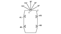
図3は、メモリ19に格納されている音響モデル31の内容を示す図である。図3に示すように、音響モデル31は、本オーディオシステム1の工場出荷時に予め作成されてメモリ19に格納された、騒音の到来方向に応じた5つの音響モデル31−30、60、90、120、150で構成されている。符号に付した2ないし3桁の数値は、マイク5への騒音の到来方向を角度で示したものであり、図4に示すように、車両2前方の右方向を基点に、30°、60°、90°、120°、150°となるように設定されている。これら5つの音響モデル31−30・・・150は、各方向からマイク5へ向かってやってくる雑音を収録し、この収録した音声信号に基づいて作成した音響モデル(GMM:Gaussian Mixture Model)であり、後述する第三動作フローの処理において、マイク5に入力された音の到来方向を同定する際に利用される音響モデルである。なお、音響モデルは、上記角度に限らず210°、240°、270°、300°、330°のモデルも使用可能である。
FIG. 3 is a diagram showing the contents of the
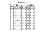
図5は、バランスマップ28の内容を示す図である。バランスマップ28は、車室内における音のバランスを規定するものである。バランスマップ28は、車両2の乗員の着座状態と各アンプ(アンプ11FR、FL、RR、RL)の増幅率との関係を定義したマップである。すなわち、バランスマップ28は、車両2の乗員の耳に届く音の音量のバランスがなるべく均等になるように、右前、左前、右後、左後のシートの座面に埋め込まれた図示しない各着座センサ(FR、FL、RR、RL)の検知状態に応じて各アンプの増幅率を定義したマップである。例えば、右前の席のみ乗員が座っており、その他の席には誰も座っていない場合、車室内で聞こえる音の中心点が右前の席付近になるように、左前、左後、右後のスピーカ4の音を増幅するアンプ11FL、RR、RLの増幅率が、アンプ
11FRよりも大きくなるように設定されている。なお、着座センサは、荷重によって乗員の有無を検知するセンサであり、着座していればオン「○」、着座していなければオフ「×」を検知する。なお、バランスマップ28では、FRの着座センサがオフの場合を定義していない。これは、オーディオシステム1が動作する際、ドライバが不在という車室内の状況は考えにくいためである。
FIG. 5 is a diagram showing the contents of the balance map 28. The balance map 28 defines the sound balance in the passenger compartment. The balance map 28 is a map that defines the relationship between the seating state of the occupant of the
図6は、係数マップ29の内容を示す図である。係数マップ29は、後述する演算処理によって同定した騒音の到来方向を基に、各アンプの増幅率を調整する際の係数を定義している。すなわち、係数マップ29は、騒音が到来する方向のスピーカの音が大きくなるように、対応するアンプの増幅率の制御パラメータに乗算する係数を定義したものであり、例えば、30〜60°の方向で外部騒音が発生している場合は右前側の音が大きくなるように、120〜150°の方向で外部騒音が発生している場合は左前側の音が大きくなるように、増幅率の制御パラメータに乗算する係数を定義している(図7参照)。
FIG. 6 is a diagram showing the contents of the
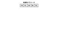
図8は、制御用パラメータ30の内容を示す図である。メモリ19内には、各アンプ11の増幅率を制御するため、図8に示すように制御用パラメータ30を格納するための記憶領域が用意されている。パラメータ「VOL」は、ユーザが操作スイッチパネル10のボリュームつまみを操作すると増減するメイン音量のパラメータである。また、パラメータ「VFR」はアンプ11FR、「VFL」はアンプ11FL、「VRR」はアンプ11RR、「VRL」はアンプ11RLの増幅率をそれぞれ個別に決定するためのパラメータであり、各パラメータにVOLやその他の変数を乗算した値が、対応するアンプ11の増幅率となる。なお、詳細については後述する。
FIG. 8 is a diagram showing the contents of the
<オーディオシステムの動作フロー>
オーディオシステム1のメイン電源がオンになると、メインユニット3の制御ユニット9では以下に示す3つの動作フローが並列に実行され、アンプユニット6やセレクタ7、ソースユニット8の制御が行われる。なお、以下に示す各動作フローは、電力の供給を受けてコンピュータプログラムの実行を開始したCPU20が、メモリ19のデータを参照し、A/Dコンバータ18や操作スイッチパネル10からの信号を受け付けて処理することで実現される。以下、各動作フローについて順に説明する。なお、説明の便宜上、各動作フローについて順に説明するが、このオーディオシステム1は、各動作フローを並行に実行するにあたって互いに相関関係を有するものではなく、例えば、第一動作フローのステップS105の処理が実行される直前に、第三動作フローのステップS305が実行されて制御用パラメータが変化しても、ステップS105の処理が中断されたりするものではない。
<Audio system operation flow>
When the main power supply of the audio system 1 is turned on, the
図9は、第一動作フローを示す図である。以下、図9を参照しつつ、オーディオシステム1で実現される第一動作フローについて説明する。 FIG. 9 is a diagram showing a first operation flow. Hereinafter, the first operation flow realized by the audio system 1 will be described with reference to FIG.
(ステップS101)オーディオシステム1のメイン電源がオンになると、CPU20ではコンピュータプログラムが実行されることで、アンプ制御部23が実現される。アンプ制御部23は、図示しない4つの着座センサからの入力点を走査して右前、左前、右後、左後の着座状態を検知する。そして、アンプ制御部23は、メモリ19内に格納されているバランスマップ28を参照し、検知した着座状態と一致するモードを索出する。例えば、1名の乗員が右前の席に着座していることを検知すれば、バランスマップ28から「モードA」を索出する。そして、バランスマップ28の「モードA」に定義されている各アンプの増幅率を読み出す。このようなバランスマップ28に基づいて各アンプの増幅率が決定されることにより、乗員が一人の場合であっても複数人の場合であっても、全員にとって音のバランスが一番良くなるように、音の中心点が調整される。
(Step S101) When the main power supply of the audio system 1 is turned on, the
(ステップS102)アンプ制御部23は、ステップS101の処理が完了したら、次に、メモリ19内の制御用パラメータ30を参照する。すなわち、アンプ制御部23は、変数VFR、VFL、VRR、VRL、VOLのパラメータを読み出す。なお、メインユニット3の起動後、後述する第三動作フローにおける係数調整処理(ステップS305)が未だ実行されていない場合、変数VFR、VFL、VRR、VRLには「1.00」が設定されている。
(Step S102) When the process of Step S101 is completed, the
(ステップS103)アンプ制御部23は、ステップS101の処理で読み出した各アンプの増幅率と、ステップS102の処理で読み出した各アンプに対応する変数VFR、VFL、VRR、VRLのパラメータとを乗算し、更にVOLを乗算する。これにより、各アンプの増幅率の制御目標値が決定される。例えば、1名の乗員が右前の席に着座しており、変数VFRが1.00、VOLが1の場合、アンプ11FRの増幅率の制御目標値が50に決定される。また、本第一動作フローと並行して実行される第三動作フローのステップS305の処理の実行により、メモリ19内に格納されている制御用パラメータ30のVFRが例えば1.2になっており、更にユーザ操作によりVOLが1.05になっていれば、アンプ11FRの増幅率の制御目標値が50×1.2×1.05=63に決定される。
(Step S103) The
(ステップS104)アンプ制御部23は、ステップS103の処理で決定した各アンプ11の増幅率をアンプユニット6の各アンプ11に制御信号で通知する。アンプ制御部23から増幅率を通知された各アンプ11は、この増幅率を制御目標値とし、セレクタ7を介してソースユニット8から送られる電気音声信号を増幅し、対応するスピーカ4へ送る。
(Step S <b> 104) The
(ステップS105)アンプ制御部23は、オーディオシステム1のメイン電源がオンのままであれば、ステップS101以降の処理を再び実行する。他方、オーディオシステム1のメイン電源がオフになっていれば、一連の処理の実行を終了する。
(Step S <b> 105) If the main power supply of the audio system 1 remains on, the
第一動作フローについては以上の通りである。次に、第二動作フローについて説明する。図10は、第二動作フローを示す図である。以下、図10を参照しつつ、オーディオシステム1で実現される第二動作フローについて説明する。 The first operation flow is as described above. Next, the second operation flow will be described. FIG. 10 is a diagram showing a second operation flow. Hereinafter, the second operation flow realized by the audio system 1 will be described with reference to FIG.
(ステップS201)オーディオシステム1のメイン電源がオンになると、CPU20でコンピュータプログラムが実行されることにより、ソース制御部24、セレクタ制御部25、操作処理部26が実現される。操作処理部26は、操作スイッチパネル10の釦の通電状態を走査し、ユーザによる操作の有無をチェックする。ユーザによるCDの再生操作、FMの受信、AMの受信、または外部入力の受付操作を検知すると、操作処理部26は、ステップS202以降の処理を実行する。
(Step S201) When the main power supply of the audio system 1 is turned on, the
(ステップS202)操作処理部26によりCDの再生操作、FMの受信、AMの受信、または外部入力の受付操作が検知されると、セレクタ制御部25は、セレクタ7に制御信号を送り、ユーザが要求するソースにセレクタスイッチ12を合わせる。
(Step S202) When the operation processing unit 26 detects a CD playback operation, FM reception, AM reception, or external input reception operation, the
(ステップS203)セレクタ制御部25によりセレクタスイッチ12の制御がなされた後、ソース制御部24は、ソースユニット8を制御し、ユーザが要求するソースを起動する。すなわち、ステップS201において、CDの再生操作がなされればCDプレーヤ13を起動し、FMの受信操作がなされればFMチューナ14を起動し、AMの受信操作がなされればAMチューナ15を起動し、外部入力の受付操作がなされれば外部入力16の回路をオンにする。
(Step S203) After the
(ステップS204)ソース制御部24によるステップS203の処理の実行が完了したのち、オーディオシステム1のメイン電源がオンのままであれば、操作処理部26は、ステップS201の処理を再び実行する。他方、オーディオシステム1のメイン電源がオフになっていれば、一連の処理の実行を終了する。 (Step S204) After the execution of the process of step S203 by the source control unit 24 is completed, if the main power supply of the audio system 1 remains on, the operation processing unit 26 executes the process of step S201 again. On the other hand, if the main power supply of the audio system 1 is turned off, execution of a series of processes is terminated.
第二動作フローについては以上の通りである。次に、第三動作フローについて説明する。図11は、第三動作フローを示す図である。以下、図11を参照しつつ、オーディオシステム1で実現される第三動作フローについて説明する。なお、本第三動作フローは、車両2の周辺で騒音があった場合に、この騒音の音声信号を基に推定した音響伝達特性と、メモリ19内に予め格納された各方向における伝達特性の音響モデル31との尤度を求めることで、騒音の到来方向を推定し、これに応じて各アンプ11の増幅率を調整するものである。
The second operation flow is as described above. Next, the third operation flow will be described. FIG. 11 is a diagram showing a third operation flow. Hereinafter, the third operation flow realized by the audio system 1 will be described with reference to FIG. In the third operation flow, when there is noise around the
(ステップS301)オーディオシステム1のメイン電源がオンになると、CPU20ではコンピュータプログラムが実行されることで、騒音判定部21、尤度算出部22、及び増幅度決定部27が実現される。コンピュータプログラムの実行によって具現化された騒音判定部21は、マイクアンプ17で増幅され、A/Dコンバータ18によってデジタル信号へ変換されたマイク5からの音声信号を取得する。
(Step S301) When the main power supply of the audio system 1 is turned on, the
(ステップS302)騒音判定部21は、マイク5からの音声信号を解析し、マイク5で観測される信号のパワーが所定の閾値を例えば1sec以上連続して超えたら(この条件が、本発明でいう所定条件に相当する)、音量調整のためのアルゴリズムであるステップS303以降の処理を尤度算出部22に実行させる。なお、所定の閾値とは、周辺騒音によりオーディオの音声が乗員に聞こえにくくなる時の周辺騒音の音量であり、車両2の防音性能等に応じて任意に設定可能なように構成されている。また、条件判定に要する所定閾値の継続時間は、1sec以外の値でもよく、例えば、ユーザが外部騒音により不快に感じ始めるよりも短い時間に設定する。
(Step S302) The
(ステップS303)尤度算出部22は、以下の処理を実行することにより、マイク5で観測した騒音の音声信号からMFCC(Mel Frequency Cepstrum Coefficient)の算出を行う。なお、MFCCとは、音声認識等、音声の分析に際して広く利用されるパラメータであって、音源(騒音源)からマイク5までの音響伝達特性の特徴をメル尺度の周波数軸でスペクトルを表現するパラメータである。尤度算出部22は、MFCCの算出を行うため、以下に示す数式1により、マイク5で得た入力音声データの高域強調(プリエンファシス)を行う。

次に、尤度算出部22は、上記数式1で高域を強調した音声データに対し、以下に示す
数式2の窓関数を適用する。これにより、有限区間内の音声データのみが残り、その後の数値解析が容易になる。
次に、尤度算出部22は、上記数式2に示す窓関数を適用した音声データに対し、フーリエ変換(FFT:Fast Fourier Transform)を行う。これにより、音声データが周波数領域に分解される。
Next, the likelihood calculating unit 22 performs a Fourier transform (FFT: Fast Fourier Transform) on the audio data to which the window function shown in
次に、尤度算出部22は、フーリエ変換後の音声データ(周波数領域)に三角フィルタ列のメルフィルタバンク処理を施す。なお、図12は、メルフィルタバンク処理の概要を図示したものである。フーリエ変換後の音声データにメルフィルタバンク処理を施すことにより、三角フィルタの数に等しいp個の出力mj(j=1,2・・・p)が算出される。mjはj番目の領域のパワースペクトルを表す。 Next, the likelihood calculating unit 22 performs mel filter bank processing of a triangular filter array on the speech data (frequency domain) after Fourier transform. FIG. 12 illustrates the outline of the mel filter bank processing. By performing Mel filter bank processing on the audio data after Fourier transform, p outputs m j (j = 1, 2,..., P) equal to the number of triangular filters are calculated. m j represents the power spectrum of the j th region.
尤度算出部22は、算出した各パワースペクトル値(mj(j=1・・・p))に対して自然対数をそれぞれとり、更に、下記の数式3による離散コサイン変換(DCT(Discrete CosineTransform)−II)を行うことにより、音声スペクトルの絶対位置を表すベクトル量であるケプストラム値を得る。
尤度算出部22は、更に、上記のケプストラム値Cn(n=1,2・・・16)に下記の数式4を適用し、再スケールを行う。
尤度算出部22は、上記演算処理により算出されたn次元のCn’をMFCCのパラメータとし、本ステップの処理を完了する。 The likelihood calculating unit 22 uses the n-dimensional C n ′ calculated by the above calculation process as a MFCC parameter, and completes the process of this step.
(ステップS304)上記ステップS303の処理の実行によりMFCCのパラメータを算出した尤度算出部22は、上記ステップS303で算出したMFCCのパラメータとメモリ19内に格納されている各音響モデル(音響モデル31−30・・・150)とをそれぞれ比較し、各方向についての尤度を算出する。図13は、各方向についての尤度を算出する際の処理内容を図示したものである。例えば、120〜150°の方向から騒音が到来した場合、各方向についての尤度は図13に示すような値になる。 (Step S304) The likelihood calculating unit 22 that has calculated the MFCC parameters by executing the processing of Step S303 described above and the MFCC parameters calculated in Step S303 and the acoustic models (acoustic models 31) stored in the memory 19 (Step S304). -30... 150) and the likelihood for each direction is calculated. FIG. 13 illustrates the processing contents when calculating the likelihood for each direction. For example, when noise comes from a direction of 120 to 150 °, the likelihood for each direction is a value as shown in FIG.
なお、音声信号に関する尤度の計算方法は次の通りである。すなわち、MFCCの特徴量をoとすると、音声尤度P(o)は下記の数式5に示すようなW個の重み付き正規分布の和として求められる。
なお、W個の正規分布のうちw番目の平均はμw、分散はσwである。また、λwは下記の数式6を満たす重み係数である。
(ステップS305)尤度算出部22が各方向の尤度を算出したら、増幅度決定部27は、上記ステップS304で算出した尤度と係数マップ29とに基づき、各アンプ11の増幅度を算出する。具体的には、増幅度決定部27は、メモリ19にアクセスして現状の制御用パラメータ30のVFR、VFL、VRR、VRLを参照する。そして、ステップS304で算出した各方向の尤度と係数マップ29の各方向に対応する値とを乗算し、更にそれらを合算したものを、各スピーカに対応する制御パラメータに乗算する。
(Step S305) When the likelihood calculating unit 22 calculates the likelihood in each direction, the
例えば、メモリ19のVFRには「1.00」が格納されており、ステップS304における演算の結果、30度方向の尤度が「1」、60度方向からの尤度が「2」、90度方向からの尤度が「3」、120度方向からの尤度が「20」、150度方向からの尤度が「15」の場合を考える。この場合、係数マップ29のFRは「5(30度)」「5(60度)」「4(90度)」「4(120度)」「3(150度)」が定義されているため、各方向の尤度と係数マップ29の各方向に対応する値とを乗算し、合算した値kFRは以下のようになる。
kFR=5*1+5*2+4*3+4*20+3*15=138
増幅度決定部27は、算出したkFRに所定の補正係数(例えば0.01)を乗算して得た値を、VFRの新たな値としてメモリ19のVFRに上書きする。このような一連の演算処理を各パラメータについてそれぞれ行い、メモリ19内に格納されている変数VFR、VFL、VRR、VRLを順次上書き更新する(この例の場合であれば、VFRは1.38、VFLは1.98、VRRは0.83、VRLは0.97が上書きされる)。
For example, “1.00” is stored in the VFR of the
kFR = 5 * 1 + 5 * 2 + 4 * 3 + 4 * 20 + 3 * 15 = 138
The amplification
第三動作フローの実行中、第一動作フローも並行して実行処理されているため、本ステップS305の処理によってメモリ19内の変数VFR、VFL、VRR、VRLが上書き更新されると、第一動作フローのステップS103で決定される各アンプの増幅率の制御目標値が本ステップS305の実行前後で変化し、各スピーカの音量が変化することとなる。よって、図13に示したように、車両2の左前方である120〜150度の方向から騒音が到来している場合、VFRが1.00から1.38へ、VFLが1.00から1.98へ上書き更新されることにより、アンプ11FL、FRの増幅率が増大してスピーカ4FL、FRの音が大きくなる。このように、車両2に到来する音の到来方向に応じて各パラメータが連続的に逐次更新されることにより、各スピーカ4の音量のバランスがとれた音響を実現できる。
During execution of the third operation flow, the first operation flow is also executed in parallel. Therefore, when the variables VFR, VFL, VRR, and VRL in the
(ステップS306)増幅度決定部27によるステップS305の処理が完了したのち、オーディオシステム1のメイン電源がオンのままであれば、騒音判定部21がステップS301以降の処理を再び実行する。他方、オーディオシステム1のメイン電源がオフになっていれば、一連の処理の実行が終了される。
(Step S306) After the process of step S305 by the amplification
以上、本実施形態に係るオーディオシステム1によれば、車両2の周辺から車室内へ騒音が到来した場合であっても、進入方向からのオーディオの音量が大きくなるように各スピーカの音量が調整されるため、周辺騒音が発生してもオーディオの音声が聞こえにくくなることがない。特に、本実施形態によれば、単一のマイク5で騒音源の方向を推定しているため、複数のマイクで音源の時間差や音差により騒音源の方向を推定するものに比べ、大幅なコスト削減やシステムの縮小化が可能である。システムの縮小化は、機器の搭載により空間に余裕が無い自動車等においてその効果が著しく、また、単一のマイク5であることにより配線の取り回し等も容易である。
As described above, according to the audio system 1 according to the present embodiment, the volume of each speaker is adjusted so that the volume of audio from the approach direction is increased even when noise comes from the vicinity of the
なお、上記実施形態では、ステップS101で乗員の着座状態に応じたモード選択を行い、各アンプの増幅率を読み出していた。しかし、本発明はこのようなものに限定されるものでなく、乗員の着座状態を無視してもよい。この場合、ステップS101における処理で全てのアンプの増幅率が同じになるようにする(例えば、モードDを選択する)。こ
れによれば、着座センサの設置等を省略することが可能であるため、システム構成を更に簡素化することが可能である。
In the above embodiment, the mode selection according to the occupant's seating state is performed in step S101, and the amplification factor of each amplifier is read. However, the present invention is not limited to this, and the seated state of the passenger may be ignored. In this case, the amplification factors of all the amplifiers are made to be the same in the process in step S101 (for example, mode D is selected). According to this, since it is possible to omit the installation of the seating sensor, the system configuration can be further simplified.
また、上記実施形態では、2chステレオの音声信号を処理するシステム構成としていた。しかし、本発明は、このようなものに限定されるものでなく、例えば、1chモノラルの音声信号や5.1chサラウンドの音声信号を処理するシステムであってもよい。 In the above embodiment, the system configuration is such that a 2ch stereo audio signal is processed. However, the present invention is not limited to this, and may be a system that processes, for example, a 1ch monaural audio signal or a 5.1ch surround audio signal.
<変形例1>
なお、上記実施形態では、第三動作フローのステップS302の処理において、音声信号のパワーや騒音の継続時間を基準に分岐処理を行っていたが、騒音判定部21は、騒音の判定を次のように行ってもよい。
<Modification 1>
In the above embodiment, in the process of step S302 of the third operation flow, the branch process is performed based on the power of the audio signal and the duration of the noise. However, the
すなわち、騒音判定部21は、走行騒音やクラクション等の雑音モデルが予め準備されたGMM(本発明でいう、第二の音響モデルに相当する)を基に、マイク5で観測された音声の信号とGMMの尤度を算出し、雑音の種類判定を行う。雑音の種類判定は、予め用意されてメモリ19に格納された複数種類の雑音のGMMをマイク5の音声信号と比較してそれぞれの尤度を算出し、最も尤度の高い雑音モデルを特定する。そして、特定された雑音モデルに対応する処理を行う。
In other words, the
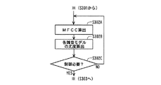
なお、特定された雑音モデルに対応する処理とは、雑音の種類に応じた各スピーカの音量調整処理であり、例えば、雑音の中でも過渡的な種類に属する場合はスピーカの音量調整を行わず、長時間継続するような雑音の場合に各スピーカの音量調整を行うことをいう。図14は、本変形例に係る動作フロー図である。本変形例はステップS302の変形例であるため、図14では、上述したステップS301、及びステップS303以降のフローを省略している。 The process corresponding to the identified noise model is a volume adjustment process for each speaker according to the type of noise.For example, if the noise belongs to a transient type, the volume of the speaker is not adjusted. This refers to adjusting the volume of each speaker in the case of noise that continues for a long time. FIG. 14 is an operation flowchart according to this modification. Since this modification is a modification of step S302, in FIG. 14, the flow after step S301 and step S303 described above is omitted.
騒音判定部21は、図14に示すように、マイク5で観測した音声信号からMFCC特徴量を算出する(S302A)。そして、騒音判定部21は、算出したMFCC特徴量とメモリ19に予め格納されている各雑音モデルとの尤度をそれぞれ算出する。そして、騒音判定部21は、最も尤度の高い雑音モデルを特定する(S302B)。騒音判定部21は、雑音の種類を特定したら、各スピーカの音量制御の要否を雑音の種類から判定する。判定条件は、図15に示すマップに定義されており、メモリ19に予め格納されている。騒音判定部21は、図15に示すマップを参照することで、各スピーカの音量制御の要否を判定する(S302C)。
As shown in FIG. 14, the
このような変形例によれば、雑音の種類に応じてスピーカ音量の制御の要否を判定しているため、過渡的な雑音によってスピーカの音量が変動することが無く、乗員がオーディオの音声を快適に聴くことができる。 According to such a modification, since it is determined whether or not the speaker volume needs to be controlled according to the type of noise, the volume of the speaker does not fluctuate due to transient noise, and the occupant can hear the audio sound. You can listen comfortably.
<変形例2>
また、上記実施形態や変形例は、次のように変形してもよい。すなわち、上述した実施形態や変形例では、マイク5を車両正面の中央部分に配置していた。しかし、上記実施形態や変形例は、マイク5を車両正面の右側に配置してもよい(図16参照)。この場合、メモリ19に格納してある音響モデル55や図6に示す係数マップは、右正面に配置したマイクで作成したものにしておく必要がある。上記実施形態や変形例は、このようにマイク5を任意の位置に配置することが可能であるため、車種に応じてマイクの取り付け箇所を選ぶこともできる。
<
Moreover, you may deform | transform the said embodiment and modification as follows. In other words, in the above-described embodiments and modifications, the
<変形例3>
また、上記実施形態や変形例は、次のように変形してもよい。すなわち、上述した実施
形態や変形例では、一つのマイク5を使っていた。しかし、マイク5が配置されている側と反対側の騒音等はマイク5が拾いにくい場合がある。このような騒音をより確実に検知するため、マイク5を複数箇所に設置してもよい(図17参照)。このようにしておくことで、例えば、大型車両のように車両の体格が大きい場合であっても車両周辺の騒音をマイク5で確実に拾うことができる。なお、本変形例は、マイク5が多数設けられているが、マイクアンプ17やA/Dコンバータ18を複数設ける必要は無い。すなわち、複数のマイク5からの信号を混合したのちにマイクアンプ17で一つの信号として処理し、A/Dコンバータ18を介してCPU20へ送る。但し、メモリ19に格納してある音響モデル55や図6に示す係数マップは複数のマイク5に基づいて作成したものにしておく必要がある。
<
Moreover, you may deform | transform the said embodiment and modification as follows. That is, in the above-described embodiments and modifications, one
<音響モデルの準備について>
以下、上記実施形態や各変形例で使用している音響モデル31について補足説明する。上記オーディオシステム1の音響モデル31は、工場出荷時に予めメモリ19に格納されたものである。音響モデル31は、上記実施形態のように、車両の正面に取り付けたマイクで各方向(すなわち、30、60、90、120、150度)からの音を収録し、収録した音に基づいて作成されたモデルである。音響モデルを準備する際の車両と、上記オーディオシステム1が搭載されるユーザの車両2とは同一でないため、メモリ19に格納される音響モデル31が車両2周辺の音響特性に適合するとは限らないが、一般的に、普通車であれば車両の外形や大きさはほとんど同じであり、車両毎の外形や大きさの違いが音響モデルに大きな影響を与えることはほとんど無いと考えられる。このため、上記実施形態では工場出荷時にメモリ19へ予め格納された音響モデル31を使い、上記一連の処理を行っている。
<Preparation of acoustic model>
Hereinafter, the
1・・・オーディオシステム
2・・・車両
3・・・メインユニット
4・・・スピーカ
5・・・マイク
6・・・アンプユニット
7・・・セレクタ
8・・・ソースユニット
9・・・制御ユニット
10・・操作スイッチパネル
DESCRIPTION OF SYMBOLS 1 ...
Claims (3)
音源となる音声信号が入力されると、該音声信号を増幅して前記各スピーカへ出力する増幅処理手段と、
車両に到来する車両周辺の音のモデルであって、音の到来方向に応じて用意された複数のモデルで構成される第一の音響モデルを記憶する記憶手段と、
車両周辺の音を検知するマイクロホンからの信号と、前記記憶手段が記憶する前記第一の音響モデルとに基づく、該車両周辺の音の到来方向に応じた制御を前記増幅処理手段へ行う音量調整手段と、を備える、
車載音響装置。 An in-vehicle audio device that outputs an audio signal to each speaker installed in a plurality of locations in a vehicle,
When an audio signal serving as a sound source is input, amplification processing means for amplifying the audio signal and outputting it to each speaker;
Storage means for storing a first acoustic model composed of a plurality of models that are models of sound around the vehicle that arrives at the vehicle and are prepared according to the direction of arrival of the sound;
Volume adjustment for performing control according to the direction of arrival of sound around the vehicle to the amplification processing unit based on a signal from a microphone that detects sound around the vehicle and the first acoustic model stored in the storage unit Means,
In-vehicle acoustic device.
請求項1に記載の車載音響装置。 The sound volume adjusting means calculates the likelihood of the signal from the microphone and the first acoustic model for each model, and a speaker installed at a position corresponding to the sound arrival direction defined in each model. Controlling the amplification processing means so that the volume is a volume according to the calculated likelihood,
The on-vehicle acoustic device according to claim 1.
前記音量調整手段は、前記マイクロホンからの信号と前記第二の音響モデルとに基づいて該車両周辺の音の種類を判別し、該音の種類に応じた前記増幅処理手段の制御を行う、
請求項1または2に記載の車載音響装置。 The storage means is a model of sound around the vehicle that arrives at the vehicle, and further stores a second acoustic model composed of a plurality of models prepared according to the type of sound,
The volume adjustment means determines the type of sound around the vehicle based on the signal from the microphone and the second acoustic model, and controls the amplification processing means according to the type of sound.
The on-vehicle acoustic device according to claim 1 or 2.
Priority Applications (1)
| Application Number | Priority Date | Filing Date | Title |
|---|---|---|---|
| JP2008314110A JP2010141468A (en) | 2008-12-10 | 2008-12-10 | Onboard acoustic apparatus |
Applications Claiming Priority (1)
| Application Number | Priority Date | Filing Date | Title |
|---|---|---|---|
| JP2008314110A JP2010141468A (en) | 2008-12-10 | 2008-12-10 | Onboard acoustic apparatus |
Publications (1)
| Publication Number | Publication Date |
|---|---|
| JP2010141468A true JP2010141468A (en) | 2010-06-24 |
Family
ID=42351221
Family Applications (1)
| Application Number | Title | Priority Date | Filing Date |
|---|---|---|---|
| JP2008314110A Withdrawn JP2010141468A (en) | 2008-12-10 | 2008-12-10 | Onboard acoustic apparatus |
Country Status (1)
| Country | Link |
|---|---|
| JP (1) | JP2010141468A (en) |
Cited By (6)
| Publication number | Priority date | Publication date | Assignee | Title |
|---|---|---|---|---|
| JP2015508187A (en) * | 2012-02-21 | 2015-03-16 | タタ コンサルタンシー サービシズ リミテッドTATA Consultancy Services Limited | Modified mel filter bang structure using spectral characteristics for sound analysis |
| JP2016043834A (en) * | 2014-08-25 | 2016-04-04 | 日野自動車株式会社 | Alarm sound generation direction notification system |
| JP2018500859A (en) * | 2015-10-29 | 2018-01-11 | 小米科技有限責任公司Xiaomi Inc. | Volume adjustment method, apparatus and terminal |
| JP2021015265A (en) * | 2019-07-15 | 2021-02-12 | バイドゥ オンライン ネットワーク テクノロジー (ベイジン) カンパニー リミテッド | Sound volume adjustment method, terminal device, storage medium, and electronic equipment |
| WO2022059911A1 (en) * | 2020-09-17 | 2022-03-24 | 삼성전자주식회사 | Electronic device, and method for controlling same |
| JP2022167043A (en) * | 2021-04-22 | 2022-11-04 | 株式会社Jvcケンウッド | audio processor |
-
2008
- 2008-12-10 JP JP2008314110A patent/JP2010141468A/en not_active Withdrawn
Cited By (10)
| Publication number | Priority date | Publication date | Assignee | Title |
|---|---|---|---|---|
| JP2015508187A (en) * | 2012-02-21 | 2015-03-16 | タタ コンサルタンシー サービシズ リミテッドTATA Consultancy Services Limited | Modified mel filter bang structure using spectral characteristics for sound analysis |
| JP2016043834A (en) * | 2014-08-25 | 2016-04-04 | 日野自動車株式会社 | Alarm sound generation direction notification system |
| JP2018500859A (en) * | 2015-10-29 | 2018-01-11 | 小米科技有限責任公司Xiaomi Inc. | Volume adjustment method, apparatus and terminal |
| JP2021015265A (en) * | 2019-07-15 | 2021-02-12 | バイドゥ オンライン ネットワーク テクノロジー (ベイジン) カンパニー リミテッド | Sound volume adjustment method, terminal device, storage medium, and electronic equipment |
| US11068235B2 (en) | 2019-07-15 | 2021-07-20 | Baidu Online Network Technology (Beijing) Co., Ltd. | Volume adjustment method, terminal device, storage medium and electronic device |
| JP7033156B2 (en) | 2019-07-15 | 2022-03-09 | バイドゥ オンライン ネットワーク テクノロジー(ペキン) カンパニー リミテッド | Volume adjustment method, terminal device, storage medium and electronic device |
| WO2022059911A1 (en) * | 2020-09-17 | 2022-03-24 | 삼성전자주식회사 | Electronic device, and method for controlling same |
| US11922970B2 (en) | 2020-09-17 | 2024-03-05 | Samsung Electronics Co., Ltd. | Electronic apparatus and controlling method thereof |
| JP2022167043A (en) * | 2021-04-22 | 2022-11-04 | 株式会社Jvcケンウッド | audio processor |
| JP7655065B2 (en) | 2021-04-22 | 2025-04-02 | 株式会社Jvcケンウッド | Audio Processing Device |
Similar Documents
| Publication | Publication Date | Title |
|---|---|---|
| US8705753B2 (en) | System for processing sound signals in a vehicle multimedia system | |
| EP1067682B1 (en) | Ambient adjusted volume control for in-vehicle messages | |
| US9172345B2 (en) | Personalized adjustment of an audio device | |
| CN113270082A (en) | Vehicle-mounted KTV control method and device and vehicle-mounted intelligent networking terminal | |
| CN112435682A (en) | Vehicle noise reduction system, method and device, vehicle and storage medium | |
| US10932042B2 (en) | Conversation assist apparatus and conversation assist method | |
| JP2010141468A (en) | Onboard acoustic apparatus | |
| CN102906811B (en) | Method for adjusting a speech recognition system comprising loudspeaker and microphone and speech recognition system | |
| US6386039B1 (en) | Method and apparatus for determining the acoustic spatial characteristics particularly of a vehicle occupant compartment in a motor vehicle | |
| US20020161543A1 (en) | Speaker detecting device | |
| JP6862871B2 (en) | In-vehicle sound processing device | |
| JP2008070878A (en) | Audio signal preprocessing device, audio signal processing device, audio signal preprocessing method, and audio signal preprocessing program | |
| JP4522509B2 (en) | Audio equipment | |
| JP2008070877A (en) | Audio signal preprocessing device, audio signal processing device, audio signal preprocessing method, and audio signal preprocessing program | |
| WO2017203688A1 (en) | Vehicle-mounted audio power consumption suppression apparatus and vehicle-mounted audio apparatus | |
| CN119052699B (en) | Vehicle-mounted sound effect adjusting method, terminal equipment and storage medium | |
| JP7734850B2 (en) | Sound reinforcement in multiple sound zone environments | |
| JP2023062165A (en) | sound player | |
| JP2018088641A (en) | Conversation assist device | |
| JP2024060150A (en) | On-vehicle audio device and method for controlling on-vehicle audio device | |
| WO2006109505A1 (en) | Audio output control device, method thereof, program thereof, and recording medium containing the program | |
| JP5201392B2 (en) | Vehicle audio device | |
| KR100803346B1 (en) | Automotive song accompaniment system with howling cancellation | |
| JP2023113171A (en) | Speech processing device, speech processing method, speech processing program, and speech processing system | |
| CN120224082A (en) | Speaker control method, device, sound effect control system, vehicle and medium |
Legal Events
| Date | Code | Title | Description |
|---|---|---|---|
| A621 | Written request for application examination |
Free format text: JAPANESE INTERMEDIATE CODE: A621 Effective date: 20111121 |
|
| A072 | Dismissal of procedure [no reply to invitation to correct request for examination] |
Free format text: JAPANESE INTERMEDIATE CODE: A073 Effective date: 20130326 |
|
| A300 | Application deemed to be withdrawn because no request for examination was validly filed |
Free format text: JAPANESE INTERMEDIATE CODE: A300 Effective date: 20130402 |