JP2010141607A - Image processor, and image processing method for same - Google Patents
Image processor, and image processing method for same Download PDFInfo
- Publication number
- JP2010141607A JP2010141607A JP2008316083A JP2008316083A JP2010141607A JP 2010141607 A JP2010141607 A JP 2010141607A JP 2008316083 A JP2008316083 A JP 2008316083A JP 2008316083 A JP2008316083 A JP 2008316083A JP 2010141607 A JP2010141607 A JP 2010141607A
- Authority
- JP
- Japan
- Prior art keywords
- pixel
- character
- data
- image
- color
- Prior art date
- Legal status (The legal status is an assumption and is not a legal conclusion. Google has not performed a legal analysis and makes no representation as to the accuracy of the status listed.)
- Pending
Links
Images


Landscapes
- Image Processing (AREA)
- Editing Of Facsimile Originals (AREA)
- Facsimile Image Signal Circuits (AREA)
- Color Image Communication Systems (AREA)
Abstract
【課題】中間調のドットを含む画像においても、解像度変換した画像に含まれる文字画像の形状を高解像度に保つことができる、画像処理装置、および画像処理装置の画像処理方法を提供する。
【解決手段】注目画素に隣接しかつ文字形状データが文字画素であることを示す画素のRGB画素データを文字画素のRGB画素データと判定し、RGB画素データが当該文字画素のRGB画素データでありかつ文字形状データが文字画素であることを示す画素の配置を表すマッチングパターンを生成し、生成したマッチングパターンが文字形状の画素の配置を示す所定のマッチングパターンと一致した場合、当該所定のマッチングパターンに含まれる注目画素に拡大処理を実行した場合の文字画素の配置に従って、拡大処理を実行した注目画素を、文字画素のRGB画素データで補間する。
【選択図】 図12An image processing apparatus and an image processing method for an image processing apparatus are provided that can maintain the shape of a character image included in a resolution-converted image at a high resolution even in an image including halftone dots.
RGB pixel data of a pixel adjacent to a target pixel and indicating that character shape data is a character pixel is determined as RGB pixel data of the character pixel, and the RGB pixel data is RGB pixel data of the character pixel. In addition, when a matching pattern representing the arrangement of pixels indicating that the character shape data is a character pixel is generated, and the generated matching pattern matches a predetermined matching pattern indicating the arrangement of the character-shaped pixels, the predetermined matching pattern In accordance with the arrangement of the character pixels when the enlargement process is performed on the target pixel included in the pixel, the target pixel on which the enlargement process has been performed is interpolated with the RGB pixel data of the character pixel.
[Selection] FIG.
Description
本発明は、画像処理装置、および画像処理装置の画像処理方法に関するものである。 The present invention relates to an image processing apparatus and an image processing method of the image processing apparatus.
レーザプリンタやデジタル複写機等においては、ビットマップ状の画像データを印字する際に、文字および画像の輪郭部の階段状の部分を補正して滑らかにするジャーキー補正が一般的に行われるようになっている。 In laser printers, digital copiers, etc., when printing bitmap image data, jerky correction is generally performed to correct and smooth the stepped portions of the outlines of characters and images. It has become.
例えば、特許文献1では、文字および図形の階段状の部分を滑らかにするジャーキー補正に加えて、トナー消費量を低減するための補正を行う画像データ処理装置を提案している。具体的には、特許文献1に記載の画像データ処理装置は、ビットマップ状に展開された画像データの注目ドットを中心とした所定範囲のドットを抽出してサンプリングし、サンプリングしたドットを基に注目ドットおよびその周囲の情報、特に、画像データの黒ドットと白ドットの境界の線分形状の特徴を認識し、その認識結果を定められたフォーマットのコード情報で表し、このコード情報を基に抽出したドットを補正する必要があるか否かを判断し、補正が必要であると判断した場合はこのコード情報をアドレスとしてジャーキー補正用のビデオデータを読み出すことにより、少ない記憶領域を用いてビットマップ状に展開された画像データの輪郭部を補正してジャーキーを無くしている。 For example, Patent Document 1 proposes an image data processing apparatus that performs correction for reducing toner consumption in addition to jerky correction for smoothing a staircase portion of characters and figures. Specifically, the image data processing device described in Patent Document 1 extracts and samples a predetermined range of dots centered on a target dot of image data developed in a bitmap shape, and based on the sampled dots Recognize the dot of interest and its surrounding information, in particular the characteristics of the line segment shape at the boundary between the black and white dots in the image data, and represent the recognition result as code information in a defined format. Based on this code information It is determined whether the extracted dots need to be corrected, and if it is determined that correction is necessary, the video data for jerky correction is read using this code information as an address, and a bit is stored using a small storage area. Jerky is eliminated by correcting the contour of the image data developed in a map.
しかしながら、上記特許文献1に記載の画像データ処理装置では、画像データの黒ドットと白ドットの境界の線分形状に対してジャーキー補正を行うものであり、ディザリングなどが施された中間調のドットにはジャーキー補正を行うことができず、中間調のドットが含まれない白黒の画像データにしかジャーキー補正を行うことができない、という課題があった。 However, the image data processing apparatus described in Patent Document 1 performs jerky correction on the line segment shape at the boundary between black dots and white dots of the image data, and is a halftone with dithering or the like. There is a problem that jerky correction cannot be performed on dots, and jerky correction can be performed only on monochrome image data that does not include halftone dots.
本発明は、上記に鑑みてなされたものであって、中間調のドットを含む画像においても、解像度変換した画像に含まれる文字画像の形状を高解像度に保つことができる、画像処理装置、および画像処理装置の画像処理方法を提供することを目的とする。 The present invention has been made in view of the above, and an image processing apparatus capable of maintaining the shape of a character image included in a resolution-converted image at a high resolution even in an image including halftone dots, and An object is to provide an image processing method of an image processing apparatus.
上述した課題を解決し、目的を達成するために、請求項1にかかる発明は、文字画像を含む画像内の各画素の色画素データおよび各画素が前記文字画像に含まれる文字画素であるか否かを示す文字形状データを生成する描画手段と、生成した各画素の前記色画素データに拡大処理を実行する拡大手段と、生成した前記文字形状データおよび前記色画素データに基づいて、拡大処理を実行した注目画素に隣接しかつ前記文字形状データが前記文字画素であることを示す画素の前記色画素データを前記文字画素の色画素データと判定し、前記色画素データが前記文字画素の色画素データでありかつ前記文字形状データが前記文字画素であることを示す画素の配置を表すマッチングパターンを生成する判定手段と、前記文字画像に含まれる前記文字画素の配置を表す所定のマッチングパターンと、生成したマッチングパターンと、が一致した場合、当該所定のマッチングパターンに画素に拡大処理を実行した場合の前記文字画素の配置を表す配置データを生成する生成手段と、生成した前記配置データが表す前記文字画素の配置に従って、拡大処理を実行した前記注目画素を、前記文字画素の色画素データで補間する補間手段と、を備えたことを特徴とする。 In order to solve the above-described problems and achieve the object, the invention according to claim 1 is a color pixel data of each pixel in an image including a character image and whether each pixel is a character pixel included in the character image. Rendering means for generating character shape data indicating whether or not, enlargement means for executing enlargement processing on the color pixel data of each pixel generated, and enlargement processing based on the generated character shape data and color pixel data The color pixel data of a pixel that is adjacent to the target pixel that has executed and indicates that the character shape data is the character pixel is determined as the color pixel data of the character pixel, and the color pixel data is the color of the character pixel. Determination means for generating a matching pattern that is pixel data and that indicates an arrangement of pixels indicating that the character shape data is the character pixel; and the character included in the character image Generation that generates arrangement data representing the arrangement of the character pixels when the predetermined matching pattern representing the arrangement of the prime matches the generated matching pattern when the pixel is subjected to enlargement processing on the predetermined matching pattern And interpolation means for interpolating the pixel of interest subjected to enlargement processing with color pixel data of the character pixel according to the arrangement of the character pixel represented by the generated arrangement data.
また、請求項2にかかる発明は、請求項1にかかる発明において、生成した前記文字形状データのうち、第1ライン数分の前記文字形状データを記憶する第1記憶手段と、前記第1記憶手段から第1画素範囲の前記文字形状データを切り出す第1切出手段と、をさらに備え、前記判定手段は、前記色画素データが前記文字画素の色画素データでありかつ前記文字形状データが前記文字画素であることを示す画素の配置を示す前記第1画素範囲の前記マッチングパターンを生成することを特徴とする。 According to a second aspect of the present invention, in the first aspect of the invention according to the first aspect, the first storage means for storing the character shape data for the first number of lines among the generated character shape data, and the first storage. First cutout means for cutting out the character shape data in the first pixel range from the means, wherein the determination means is such that the color pixel data is color pixel data of the character pixel and the character shape data is the character shape data. The matching pattern of the first pixel range indicating the arrangement of pixels indicating character pixels is generated.
また、請求項3にかかる発明は、請求項1または2にかかる発明において、前記補間手段は、拡大処理を実行した前記注目画素が下地である場合に、拡大処理を実行した前記注目画素を、前記文字画素の色画素データで補間することを特徴とする。 The invention according to claim 3 is the invention according to claim 1 or 2, wherein, when the pixel of interest for which the enlargement processing has been performed is a background, the interpolation unit determines the pixel of interest for which the enlargement processing has been performed, Interpolation is performed using color pixel data of the character pixels.
また、請求項4にかかる発明は、請求項3にかかる発明において、前記補間手段は、前記色画素データが白を示す画素を下地と認識することを特徴とする。 The invention according to claim 4 is the invention according to claim 3, wherein the interpolation means recognizes a pixel in which the color pixel data indicates white as a background.
また、請求項5にかかる発明は、請求項1から4のいずれか一にかかる発明において、生成した前記色画素データのうち、第2ライン数分の前記色画素データを記憶する第2記憶手段と、前記第2記憶手段から第2画素範囲の前記色画素データを切り出す第2切出手段と、をさらに備え、前記判定手段は、生成した前記文字形状データおよび前記第2画素範囲の前記色画素データに基づいて、前記注目画素に隣接しかつ前記文字形状データが前記文字画素であることを示す画素の前記色画素データを前記文字画素の色画素データと判定することを特徴とする。 According to a fifth aspect of the present invention, in the invention according to any one of the first to fourth aspects, a second storage unit that stores the color pixel data for the second number of lines among the generated color pixel data. And second cutout means for cutting out the color pixel data of the second pixel range from the second storage means, and the determination means includes the generated character shape data and the color of the second pixel range. Based on pixel data, the color pixel data of a pixel adjacent to the target pixel and indicating that the character shape data is the character pixel is determined as the color pixel data of the character pixel.
また、請求項6にかかる発明は、請求項5にかかる発明において、前記第2画素範囲が前記第1画素範囲より狭いことを特徴とする。
The invention according to
また、請求項7にかかる発明は、描画手段が、文字画像を含む画像内の各画素の色画素データおよび各画素が前記文字画像に含まれる文字画素であるか否かを示す文字形状データを生成する描画工程と、拡大手段が、生成した各画素の前記色画素データに拡大処理を実行する拡大工程と、判定手段が、生成した前記文字形状データおよび前記色画素データに基づいて、拡大処理を実行した注目画素に隣接しかつ前記文字形状データが前記文字画素であることを示す画素の前記色画素データを前記文字画素の色画素データと判定し、前記色画素データが前記文字画素の色画素データでありかつ前記文字形状データが前記文字画素であることを示す画素の配置を表すマッチングパターンを生成する判定工程と、生成手段が、前記文字画像に含まれる前記文字画素の配置を表す所定のマッチングパターンと、生成したマッチングパターンと、が一致した場合、当該所定のマッチングパターンに画素に拡大処理を実行した場合の前記文字画素の配置を表す配置データを生成する生成工程と、補間手段が、生成した前記配置データが表す前記文字画素の配置に従って、拡大処理を実行した前記注目画素を、前記文字画素の色画素データで補間する補間工程と、を有することを特徴とする。 According to a seventh aspect of the present invention, the drawing means includes color pixel data of each pixel in an image including a character image and character shape data indicating whether each pixel is a character pixel included in the character image. A drawing step to be generated, an enlargement step in which the enlargement unit executes an enlargement process on the color pixel data of each pixel generated, and an enlargement process based on the character shape data and the color pixel data generated by the determination unit The color pixel data of a pixel that is adjacent to the target pixel that has executed and indicates that the character shape data is the character pixel is determined as the color pixel data of the character pixel, and the color pixel data is the color of the character pixel. The character image includes a determination step for generating a matching pattern representing pixel arrangement indicating pixel data and the character shape data indicating the character pixel, and a generation unit. When the predetermined matching pattern representing the arrangement of the character pixels matches the generated matching pattern, the arrangement data representing the arrangement of the character pixels when the pixel is enlarged according to the predetermined matching pattern is generated. And an interpolation step in which the interpolation means interpolates the pixel of interest that has been subjected to the enlargement process with the color pixel data of the character pixel according to the arrangement of the character pixel represented by the generated arrangement data. It is characterized by.
本発明によれば、文字画像が中間調で表現される場合であっても、文字画像の輪郭部の階段状の部分を補間することができるので、中間調のドットを含む画像においても、解像度変換した画像に含まれる文字画像の形状を高解像度に保つことができる、という効果を奏する。 According to the present invention, even if the character image is expressed in halftone, the stepped portion of the contour portion of the character image can be interpolated, so even in an image including halftone dots, the resolution There is an effect that the shape of the character image included in the converted image can be maintained at a high resolution.
以下に添付図面を参照して、この発明にかかる画像処理装置、および画像処理装置の画像処理方法の最良な実施の形態を詳細に説明する。なお、本実施の形態では、この発明にかかる画像処理装置、および画像処理装置の画像処理方法をプリンタである多色画像形成装置に適用した例について説明するが、文字画像を含む画像に画像処理を施すものであれば、これに限定するものではない。例えば、複写機、ファクシミリ、複合機などの画像処理装置にも適用することができる。 Exemplary embodiments of an image processing apparatus and an image processing method of the image processing apparatus according to the present invention are explained in detail below with reference to the accompanying drawings. In the present embodiment, an example in which the image processing apparatus according to the present invention and the image processing method of the image processing apparatus are applied to a multicolor image forming apparatus that is a printer will be described. However, the present invention is not limited to this. For example, the present invention can be applied to an image processing apparatus such as a copying machine, a facsimile machine, and a multifunction machine.
図1は、本実施の形態にかかる多色画像形成装置の構成を示すブロック図である。本実施の形態にかかる多色画像形成装置において、符号1は像担持体であるベルト状の感光体であり、その感光体1は回転ローラ2、3により回動可能に支持され、その各回転ローラ2、3の駆動により矢示A方向に回動される。感光体1の外周部には、帯電手段である帯電装置4、除電ランプL、感光体1用のクリーニングブレード15Aが配置されている。帯電装置4の下流位置には、光書込手段であるレーザ書き込みユニット5より発せられるレーザ光が照射される光書き込み部がある。
FIG. 1 is a block diagram showing a configuration of a multicolor image forming apparatus according to the present embodiment. In the multicolor image forming apparatus according to the present embodiment, reference numeral 1 denotes a belt-like photoconductor that is an image carrier, and the photoconductor 1 is rotatably supported by rotating rollers 2 and 3, and each rotation thereof. The rollers 2 and 3 are driven to rotate in the direction of arrow A. On the outer periphery of the photoreceptor 1, a charging device 4 as a charging unit, a static elimination lamp L, and a
光書き込み部より下流位置には、複数の現像ユニット(現像手段)が切り換え自在に支持された多色現像装置6が配置されている。多色現像装置6は、収容するトナーの色毎に、イエロー現像ユニット、マゼンタ現像ユニット、シアン現像ユニットを備えている。多色現像装置6の上部には、黒色トナーを収容したブラック現像ユニット7が備えられている。
A multi-color developing
これらの各現像ユニットのいずれか1つが対応する色の現像タイミングに同期し、現像可能な位置に移動する。多色現像装置6は、円周上120度の回転によっていずれかの現像ユニットを選択する機能を有している。そして、これらの現像ユニットが稼動するときには、ブラック現像ユニット7は感光体1より離間した位置に移動する。その移動は、カム45の回転により行なわれる。
Any one of these development units moves to a developable position in synchronization with the development timing of the corresponding color. The multicolor developing
レーザ書き込みユニット5は、図示しないレーザ光源から複数色の画像形成信号(書き込み情報)に応じたレーザ光を順次発生させ、ポリゴンモータ5Aによって回転されるポリゴンミラー5Bを用いてそのレーザ光を周期的に偏向させ、fθレンズ5Cおよびミラー5Dなどを経て、帯電された感光体1の表面を走査してその表面に静電潜像を形成させる。
The laser writing unit 5 sequentially generates laser light according to image forming signals (writing information) of a plurality of colors from a laser light source (not shown), and periodically uses the
感光体1の表面に形成される静電潜像は、対応する現像ユニットからのトナーによって現像され、トナー画像が形成・保持される。中間転写ベルト10は、感光体1に隣接しており、回転ローラ11、12により矢示B方向に回動可能に支持されている。感光体1上のトナー画像は、中間転写ベルト10の裏側にある転写ブラシ(第1の転写手段)13により、その中間転写ベルト10の表面に転写される。
The electrostatic latent image formed on the surface of the photoreceptor 1 is developed with toner from the corresponding developing unit, and a toner image is formed and held. The
感光体1の表面は1色毎にクリーニングブレード15Aによりクリーニングされ、その表面に所定色のトナー画像が形成される。そして、その都度中間転写ベルト10の1回動毎にその表面の同じ位置に感光体1上のトナー画像が転写されて、中間転写ベルト10上に複数色のトナー画像が重ね合わせられて保持される。その後、そのトナー画像は用紙やプラスチック等の記録媒体に転写される。
The surface of the photoreceptor 1 is cleaned for each color by the
用紙への転写に際しては、給紙装置(給紙カセット)17に収納されている用紙が給紙ローラ18によって繰り出されて搬送ローラ19により搬送され、レジストローラ対20に付き当てられた状態で一旦停止された後、トナー画像の転写位置が正規のものとなるようにタイミングがとられて中間転写ベルト10と転写ローラ(第2の転写手段)14のニップに再搬送される。そして、その用紙は転写ローラ14の作用により中間転写ベルト10上の複数色のトナー画像が一括転写された後、定着装置50に送られ、そこでトナー像が定着された後、排紙ローラ対51により本体フレーム9の上部の排紙スタック部52に排出される。
At the time of transfer onto the paper, the paper stored in the paper feeding device (paper feeding cassette) 17 is fed out by the
中間転写ベルト10には、回転ローラ11の部位に中間転写ベルト10用のクリーニング装置16が設けられ、クリーニングブレード16Aがクリーニングブレード接離用アーム16Cを介して接離自在の構成となっている。このクリーニングブレード16Aは、感光体1からトナー画像を受け取る工程では、中間転写ベルト10から離れ、中間転写ベルト10より用紙にトナー画像が転写された後に接触するようになっていて、用紙にトナー画像が転写された後の残留トナーをかきとる。クリーニングブレードは、すでに記したように、感光体1用と中間転写ベルト10用がある。これらブレードがかきとった廃トナーは、回収容器15に収納する。その回収容器15は適宜交換される。中間転写ベルト10用のクリーニング装置16の内部に設けられたオーガ16Bが、クリーニングブレード16Aでかきとられた廃トナーを搬送し、図示しない搬送手段で回収容器15に送るようになっている。
The
符号31はユニット化されたプロセスカートリッジで、感光体1、帯電装置4、中間転写ベルト10、クリーニング装置16、用紙搬送路を形成する搬送ガイド30などを一体に組み込み、寿命到来時に交換できるように構成されている。プロセスカートリッジ31の交換のほかに、多色現像装置6、ブラック現像ユニット7なども寿命到来時に交換するが、その交換性やジャム紙の処理を容易にするため、本体の一部の前フレーム8は支軸9Aを中心に開閉可能に回動できる構造にしてある。
図1の左側には、電装・制御装置60が収納されている。その上方には、ファン58が備えられており、機内の温度過昇防止のために排風する。図の右側には、比較的小規模な別の給紙装置59が備えられている。なお、この実施形態では、中間転写体として中間転写ベルト10を使用したが、中間転写ドラムを使用することもできる。
On the left side of FIG. 1, an electrical /
図2は、多色画像形成装置の電装・制御装置のハードウェア構成の例を示す図である。図2の電装・制御装置60は、プリンタコントローラボード121が、ネットワークを介してPC(Personal Computer)120に対して接続され、また、プリンタエンジン122と接続される。
FIG. 2 is a diagram illustrating an example of the hardware configuration of the electrical / control apparatus of the multicolor image forming apparatus. 2 has a
プリンタコントローラボード121は、メモリコントローラ内蔵CPU(Central Processing Unit)115、画像処理ASIC(Application Specific Integrated Circuit)117、およびパネル制御ASIC118を有し、これらがバス116を介して接続されている。メモリコントローラ内蔵CPU115は、さらに、メインメモリ114およびROM(Read Only Memory)113と接続されている。
The
メモリコントローラ内蔵CPU115は、CPU101、CPU I/F(Interface)102、メモリアービタ103、通信コントローラ107、描画装置105、メモリコントローラ104、及び、バスコントローラ106を有する。
The memory controller built-in
CPU101は、多色画像形成装置の装置全体の制御を行う。CPU101は、また、PC120から伝送されるPDL(Page Description Language)を解析し、描画装置105に対する描画コマンドの出力、及び、画像処理ASIC117に対する画像処理パラメータの生成等を行う。CPU I/F102は、CPU101のインタフェースであり、メモリアービタ103を介してメインメモリ114及び他のコントローラ等に接続されている。
The
メモリアービタ103は、メモリコントローラ内蔵CPU115が有する各コントローラの、メインメモリ114に対するアクセスの調停を行う。メモリコントローラ104は、メインメモリ114の制御を行う。メモリコントローラ104は、メモリアービタ103を介して各コントローラと接続される。
The
バスコントローラ106は、バスに対してデータを入出力する各コントローラ及びバスの間の調停を行う。通信コントローラ107は、ネットワークに接続され、ネットワークを介して接続されたPC120等から送信される各データやコマンド等を受信する。通信コントローラ107は、また、メモリアービタ103を介して接続される各コントローラに対して受信したデータ等を出力し、各コントローラから入力されるデータ等を、PC120等に対して送信する。
The
描画装置105は、CPU101から入力された描画コマンドに従って、文字画像を含む画像をRGB空間で表した各画素のRGB画素データ、および各画素が文字画像に含まれる文字画素であるか否かを示す文字形状データを生成し、生成したRGB画素データおよび文字形状データをメインメモリ114に描画する。ここで、描画装置105により生成されるデータは、多色画像形成装置が画像を処理する単位の一である「バンド」単位のバンドデータである。
In accordance with a drawing command input from the
ROM113は、CPU101が実行するコンピュータプログラムや、文字のフォント情報等を格納する。メインメモリ114は、描画装置105により生成されたRGB画素データや文字形状データ、それらのデータが圧縮された符号データ、及び、CPU101が実行するコンピュータプログラム等が格納される。
The
なお、本実施の形態の多色画像形成装置で実行されるプログラムは、ROM等に予め組み込まれて提供されるが、インストール可能な形式又は実行可能な形式のファイルでCD−ROM、フレキシブルディスク(FD)、CD−R、DVD(Digital Versatile Disk)等のコンピュータで読み取り可能な記録媒体に記録して提供するように構成してもよい。 Note that the program executed by the multicolor image forming apparatus of the present embodiment is provided by being incorporated in advance in a ROM or the like. However, a CD-ROM, a flexible disk ( (FD), CD-R, DVD (Digital Versatile Disk), and the like may be recorded and provided on a computer-readable recording medium.
さらに、本実施の形態の多色画像形成装置で実行されるプログラムを、インターネット等のネットワークに接続されたコンピュータ上に格納し、ネットワーク経由でダウンロードさせることにより提供するように構成しても良い。また、本実施の形態の多色画像形成装置で実行されるプログラムをインターネット等のネットワーク経由で提供または配布するように構成しても良い。 Furthermore, the program executed by the multicolor image forming apparatus of the present embodiment may be provided by being stored on a computer connected to a network such as the Internet and downloaded via the network. The program executed by the multicolor image forming apparatus of the present embodiment may be provided or distributed via a network such as the Internet.
画像処理ASIC117は、画像処理装置110、バスインタフェースI/F(Interface)108、及び、エンジンコントローラ109を有する。画像処理装置110は、CPU101により生成された画像処理パラメータが入力され、その画像処理パラメータに従う画像処理を行う。
The
バスI/F108は、画像処理ASIC117がバスに接続される際のインタフェースである。エンジンコントローラ109は、プリンタエンジン122の制御を行う。
The bus I /
パネル制御ASIC118は、パネル119に接続され、CPU101からの制御コマンド等に従い、パネル119の制御を行う。パネル制御ASIC118は、パネルコントローラ112及びバスI/F111を有する。パネルコントローラ112は、パネル119に表示するデータの制御、及び、パネル119から入力される情報の取得等を行う。バスI/F111は、バスに接続され、メモリコントローラ内蔵CPU115からのデータの入出力を行う。
The
パネル119は、多色画像形成装置の状態の表示を行い、また、多色画像形成装置に対する操作者による指示を受け付ける。
The
プリンタエンジン122は、エンジンコントローラ109の制御により、画像を媒体上に形成する。PC120は、多色画像形成装置に出力させる画像のPDLを作成し、ネットワークを介してPDLを多色画像形成装置に対して出力する。
The
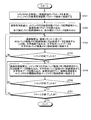
図3は、多色画像形成装置における処理の概略を示すフロー図である。図3では、入力されたPDLが解析され、画像処理された後、プリンタエンジン122に対して出力される。図3における処理は、PDL記憶ステップ(ステップS301)、PDL解析ステップ(ステップS302)、描画処理ステップ(ステップS303)、RGBバンド画像記憶ステップ(ステップS304)、文字形状バンド記憶ステップ(ステップS305)、画像処理ステップ(ステップS320)、階調処理後ページ画像記憶ステップ(ステップS309)、およびプリントアウトステップ(ステップS310)を有し、上記の順に各ステップの処理が実行される。
FIG. 3 is a flowchart showing an outline of processing in the multicolor image forming apparatus. In FIG. 3, the input PDL is analyzed, subjected to image processing, and then output to the
PDL記憶ステップ(ステップS301)では、メインメモリ114が、PC120から入力されるPDLを格納する。PDL解析ステップ(ステップS302)では、CPU101が、コンピュータプログラムを実行することにより、メインメモリ114に格納されているPDLを解析して生成した描画コマンドを描画装置105に出力する。
In the PDL storage step (step S301), the
描画処理ステップ(ステップS303)では、描画装置105が、CPU101から入力された描画コマンドに従って、RGB画素データおよび文字形状データを生成してメインメモリ114に転送する。
In the drawing process step (step S303), the
RGBバンド画像記憶ステップ(ステップS304)および文字形状バンド記憶ステップ(ステップS305)では、描画装置105から転送されたRGB画素データおよび文字形状データをバンド単位でメインメモリ114に記憶する。
In the RGB band image storage step (step S304) and the character shape band storage step (step S305), the RGB pixel data and the character shape data transferred from the
画像処理ステップ(ステップS320)は、解像度変換ステップ(ステップS306)、色変換処理ステップ(ステップS307)、および階調処理ステップ(ステップS308)を有する。解像度変換ステップ(ステップS306)では、メインメモリ114からRGB画素データおよび文字形状データを読み込み、RGB画素データの解像度を変換(例えば、600dpi→1200dpi)する。
The image processing step (step S320) includes a resolution conversion step (step S306), a color conversion processing step (step S307), and a gradation processing step (step S308). In the resolution conversion step (step S306), RGB pixel data and character shape data are read from the
色変換処理ステップ(ステップS307)では、ステップS306で解像度が変換されたRGB画素データおよびに対し、色空間変換処理が行われ、CMYK画素データが生成される。 In the color conversion processing step (step S307), color space conversion processing is performed on the RGB pixel data whose resolution has been converted in step S306, and CMYK pixel data is generated.
階調処理ステップS308では、ステップS307において色空間変換が行われたCMYK画素データに対し、ハーフトーン処理が行われる。 In the gradation processing step S308, halftone processing is performed on the CMYK pixel data subjected to the color space conversion in step S307.
階調処理後ページ画像記憶ステップ(ステップS309)では、メインメモリ114に、ステップS308のハーフトーン処理により得られたハーフトーン処理後データが格納される。ステップS309の処理の後、プリントアウトステップ(ステップS310)では、プリンタエンジン122がメインメモリ114に格納されたハーフトーン処理後データを印刷して出力する。
In the post-gradation processing page image storing step (step S309), the post-halftone processing data obtained by the halftone processing in step S308 is stored in the
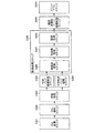
図4は、メインメモリの記憶領域を説明する図である。図5は、600dpiのRGB画素データの一例を示す図である。図6は、600dpiの文字形状データの一例を示す図である。メインメモリ114は、PDL格納メモリ領域、プログラム領域、RGBバンド画像メモリ格納領域、文字形状バンド画像メモリ格納領域、画像処理パラメータ領域、階調処理後ページメモリ格納領域、拡大補正メモリ格納領域、およびその他の領域を有する。
FIG. 4 is a diagram for explaining a storage area of the main memory. FIG. 5 is a diagram illustrating an example of 600 dpi RGB pixel data. FIG. 6 is a diagram illustrating an example of 600 dpi character shape data.
PDL格納メモリ領域は、PC120から入力されたPDLを格納する。プログラム領域は、CPU101が実行するコンピュータプログラムを格納する。RGBバンド画像メモリ格納領域は、描画装置105により生成された画像のRGB画素データ(図5に示す)を、バンド単位に格納する。文字形状バンド画像メモリ格納領域は、描画装置105により生成された文字形状データ(図6に示す)を、バンド単位に格納する。
The PDL storage memory area stores the PDL input from the
画像処理パラメータ領域は、格子点データ格納領域、ガンマデータ格納領域、しきい値データ格納領域、およびDMA(Direct Memory Access)パラメータ格納領域を有する。格子点データ格納領域およびガンマデータ格納領域は、色変換処理ステップS306において色空間変換を行う際のパラメータを格納する。 The image processing parameter area includes a lattice point data storage area, a gamma data storage area, a threshold data storage area, and a DMA (Direct Memory Access) parameter storage area. The grid point data storage area and the gamma data storage area store parameters for performing color space conversion in the color conversion processing step S306.
しきい値データ格納領域は、階調処理ステップS308において、ハーフトーン生成処理を行う際のしきい値テーブルを格納する。しきい値データ格納領域に格納されるしきい値テーブルは、ハーフトーン処理を行う画像データを構成する色コンポーネント毎に設けられてよい。 The threshold value data storage area stores a threshold value table used when halftone generation processing is performed in the gradation processing step S308. The threshold value table stored in the threshold value data storage area may be provided for each color component constituting the image data to be subjected to halftone processing.
DMAパラメータ格納領域は、画像処理パラメータを読み込む際に用いたアドレス等のパラメータを格納する。 The DMA parameter storage area stores parameters such as an address used when reading image processing parameters.
階調処理後ページメモリ格納領域は、C版ページメモリ格納領域、M版ページメモリ格納領域、Y版ページメモリ格納領域、および、K版ページメモリ格納領域を有する。階調処理後ページメモリ格納領域が有す各格納領域は、ハーフトーン処理された後の色コンポーネント毎に設けられるとよく、CMYK色空間の他に、例えば、RGB色空間の色コンポーネント毎に対応して設けられてもよい。 The post-gradation page memory storage area has a C-page memory area, a M-page memory area, a Y-page memory area, and a K-page memory area. Each storage area of the page memory storage area after gradation processing is preferably provided for each color component after halftone processing. For example, in addition to the CMYK color space, each storage area corresponds to each color component in the RGB color space. May be provided.
拡大補正メモリ格納領域は、解像度変換ステップS306で解像度変換に用いる拡大補正パラメータを格納する。 The enlargement correction memory storage area stores enlargement correction parameters used for resolution conversion in the resolution conversion step S306.
図7は、本実施の形態にかかる画像処理全体の動作処理を示すフローチャートである。まず、CPU101はPDLを解析し、画像処理装置110の画像処理パラメータを生成し、メインメモリ114の画像処理装置パラメータ領域へ格納する(ステップS701)。続いて、画像処理装置110は、メインメモリ114の画像処理パラメータ領域から画像処理パラメータを読み込み、さらに拡大補正メモリ格納領域から拡大補正パラメータを読み込む(ステップS702)。描画装置105は、CPU101から入力された描画コマンドに従って、RGB画素データを生成し、RGBバンド画像メモリ格納領域に描画する(ステップS703)。この時、描画装置105は、RGB画素データが文字形状を含む場合には、文字形状データを生成し、生成した文字形状データを文字形状バンド画像メモリ格納領域に描画する。このステップS703の処理を1バンドが終了するまで繰り返し(ステップS704:No)実行する。上記1バンドの処理が終了すると(ステップS704:Yes)、画像処理装置110は、メインメモリ114のRGBバンド画像メモリ格納領域からRGB画素データを読み込み、さらに文字形状バンド画像メモリ格納領域から文字形状データを読み込んで画像処理を行い、画像処理結果をメインメモリ114の階調処理後ページメモリ格納領域へ転送する(ステップS705)。このステップS705の処理を1バンド終了するまで(ステップS706:No)繰り返し実行する(ステップS706:Yes)。このように、上記ステップS703〜S706の処理を1バンドについて終了するまで(ステップS707:No)実行する(ステップS707:Yes)。
FIG. 7 is a flowchart showing the operation processing of the entire image processing according to this embodiment. First, the
図8は、画像処理装置のハードウェア構成を説明する図である。図8の画像処理装置110は、RGB画素データアドレス生成装置811、RGB画素データ読み込み装置810、文字形状データアドレス生成装置813、文字形状データ読み込み装置812、解像度変換装置814、色変換処理装置815、ハーフトーン処理装置816、パラメータアドレス生成装置803、画像処理パラメータ読み込み装置802、DMAパラメータ記憶装置804、マッチングパターン記憶装置805、格子点データ記憶装置806、ガンマテーブル記憶装置807、ハーフトーンパラメータ記憶装置808、しきい値マトリックス記憶装置809、画像処理後画像アドレス生成装置818、画像処理後画像書き込み装置819、画像処理後画像バッファー装置817、およびバスアービタI/F801を有する。
FIG. 8 is a diagram illustrating the hardware configuration of the image processing apparatus. 8 includes an RGB pixel data address
バスアービタ−I/F801は、RGB画素データ読み込み装置810、文字形状データ読み込み装置812、画像処理パラメータ読み込み装置802、および画像処理後画像書き込み装置819のそれぞれが、バスI/F108を介してバス116に対してデータを入出力する際の調停を行う。
The bus arbiter I /
パラメータアドレス生成装置803は、メインメモリ114上の画像処理パラメータ領域に格納されているパラメータのアドレスを生成する。画像処理パラメータ読み込み装置801は、パラメータアドレス生成装置803により生成されたアドレスにより、メインメモリ114に格納されている画像処理パラメータを読み出す。
The parameter
DMAパラメータ記憶装置804は、画像処理パラメータ読み込み装置802が画像処理パラメータを読み込む際に用いたアドレス等のパラメータを、画像処理パラメータ読み込み装置802から受信して格納する。DMAパラメータ記憶装置804が格納するパラメータは、バンドの幅である多値RGBバンド幅、バンドの高さである多値RGBバンド高さ、バンドデータのメインメモリ114上の開始アドレスであるRGBバンドスタートアドレス、階調処理された後のバンドの幅と高さである階調処理後CMYKバンド幅及び階調処理後CMYKバンド高さ、並びに、C、M、Y、Kそれぞれの色コンポーネントのバンドデータをメインメモリ114上に格納する際のスタートアドレス等である。
The DMA
マッチングパターン記憶装置805は、解像度変換に必要なマッチングパターンデータなどを格納するものである。本実施の形態では、マッチングパターン記憶装置805は、拡大処理を実行する注目画素を中心とし、文字画像に含まれる文字画素の配置を表す所定のマッチングパターンと、当該所定のマッチングパターンが含む注目画素に拡大処理を実行した場合の文字画素の配置を表す配置データと、を対応付けて格納するものである。
The matching
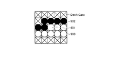
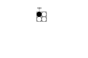
図9は、所定のマッチングパターンの一例を示す図である。図10は、配置データの一例を示す図である。図9に示す所定のマッチングパターンは、注目画素901を中心に、文字画素である黒の画素902、文字画素以外の白の画素903、および×で示すDon’t Careが配置されたマッチングパターンである。図10に示す配置データは、図9に示す所定のマッチングパターンに含まれる注目画素901に拡大処理を実行した場合の文字画素(黒の画素)1001を示すものである。
FIG. 9 is a diagram illustrating an example of a predetermined matching pattern. FIG. 10 is a diagram illustrating an example of arrangement data. The predetermined matching pattern shown in FIG. 9 is a matching pattern in which a
さらに、マッチングパターン記憶装置805は、白の画素に拡大処理を実行した場合の文字形状データを格納するものとする。図11は、白の画素に拡大処理を実行した場合の配置データの一例を示す図である。図11に示す配置データは、白の画素に拡大処理を実行した場合の文字形状を示すものである。
Furthermore, it is assumed that the matching
RGB画素データアドレス生成装置811は、メインメモリ114に記憶されたRGB画素データから、水平ライン毎にRGB画素データを読み出す際のアドレスを生成する。
The RGB pixel data address
RGB画素データ読み込み装置810は、メインメモリ114上のRGBバンド画像メモリ格納領域から、RGB画素データアドレス生成装置811により生成された水平ライン毎のアドレスにより、メインメモリ114からRGB画素データを読み込む。
The RGB pixel
文字形状データアドレス生成装置813は、メインメモリ114に記憶された文字形状データから、水平ライン毎に文字形状データを読み出す際のアドレスを生成する。
The character shape data address
文字形状データ読み込み装置812は、メインメモリ114上の文字形状バンド画像メモリ格納領域から、文字形状データアドレス生成装置813により生成されたアドレスにより、水平ライン毎に文字形状データを読み込む。
The character shape
解像度変換装置814は、マッチングパターン記憶装置805に格納されているマッチングパターンデータおよび文字形状データ読み込み装置812により読み込んだ文字形状データを用いて、RGB画素データ読み込み装置810により読み込だRGB画素データの解像度を、メインメモリ114上の拡大補正メモリ格納領域に格納された拡大補正パラメータが示す解像度に変換する(例えば、600dpi→1200dpi)。
The
色変換処理装置815は、解像度変換装置814から入力されるRGB画素データの画素値に対し、色空間変換処理(BG/UCR処理)を行う。色変換処理装置815は、入力されるRGB画素データを、RGB色空間からCMYK色空間のCMYK画素データに変換する。
The color
色変換処理装置815は、色空間変換の他に、下色除去、色補正等の処理を行う。色変換処理装置815は、処理に用いるパラメータを格子点データ記憶装置806及びガンマテーブル記憶装置807から取得する。
The color
格子点データ記憶装置806は、画像処理パラメータ読み込み装置802から入力される格子点データを記憶する。ガンマテーブル記憶装置807は、画像処理パラメータ読み込み装置802から入力されるガンマ補正用のパラメータを含むガンマテーブルを記憶する。
The lattice point
ハーフトーン処理装置816は、色変換処理装置815から入力されるCMYK画素データの色コンポーネント毎に、ハーフトーン処理を行う。ハーフトーン処理装置816は、ハーフトーン処理に必要なパラメータをハーフトーンパラメータ記憶装置808から読み出す。ハーフトーン処理装置816は、さらに、入力されるCMYK画素データの奇数画素と偶数画素とのそれぞれに対し、奇数閾値マトリックスに含まれる値と偶数閾値マトリックスに含まれる値とによる比較により、ハーフトーン処理を行う。ハーフトーン処理装置816は、ハーフトーン処理後のCMYK画素データを、メインメモリ114のワード単位にハーフトーン処理後データとして出力する。
The
ハーフトーンパラメータ記憶装置808は、メインメモリ114から読み出されたハーフトーン処理装置816がハーフトーン処理する際のパラメータを記憶する。しきい値マトリックス記憶装置809は、それぞれ、CMYK画素データの水平ラインの位置に基づいて、奇数画素と偶数画素とに対応するハーフトーン処理のためのしきい値マトリックスを記憶する。
The halftone
画像処理後画像バッファー装置817は、ハーフトーン処理装置816によりハーフトーン化されたCMYK画素データを保持する。画像処理後画像バッファー装置817は、メインメモリ114に書き込み処理を行う際の、バーストレングスに対応する数のハーフトーン化されたCMYK画素データを保持する。
The post-image processing
画像処理後画像書き込み装置819は、画像処理後画像バッファー装置817に格納されているハーフトーン化されたCMYK画素データを、バス116を介してメインメモリ114に対して出力する。画像処理後画像書き込み装置819は、メインメモリ114のワード単位で、CMYK画素データを出力する。
The post-image processing
画像処理後画像アドレス生成装置818は、画像処理後画像書き込み装置819がCMYK画素データをメインメモリ114に格納させる際の、アドレスを生成する。画像処理後画像アドレス生成装置818は、DMAパラメータ記憶装置804に格納されているパラメータに基づいて、メインメモリ114上のアドレスを生成する。より詳細には、RGB画素データ読み込み装置810がRGB画素データを読み込む際と同様に、CMYK画素データの水平ラインのアドレスを生成する。
The post-image processing image
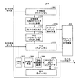
図12は、解像度変換装置のハードウェア構成を説明する図である。図12の解像度変換装置814は、文字形状Mラインメモリ1201、文字形状N*Mマトリックス切り出し装置1202、RGB Bラインメモリ1203、RGB A*Bマトリックス切り出し装置1204、文字色判定装置1205、パターンアドレス生成装置1206、Delayメモリ1207、2*2拡大装置1208、下地認識装置1209、RGBラインメモリコントローラ1210、およびRGB1ラインメモリ1211を有する。
FIG. 12 is a diagram illustrating the hardware configuration of the resolution conversion apparatus. 12 includes a character shape
文字形状Mラインメモリ1201は、文字形状データ読み込み装置812により読み込まれたNライン分の文字形状データを記憶するものである。
The character shape
文字形状N*Mマトリックス切り出し装置1202は、文字形状Mラインメモリ1201に記憶されたNライン分の文字形状データから、注目画素を中心とするN*Mマトリックス(第1画素範囲)の文字形状データを切り出すものである。なお、本実施の形態では、注目画素を中心とするN*Mマトリックスの文字形状データを切り出しているが、N*Mマトリックス内に注目画素が含まれていれば、これに限定するものではない。
The character shape N * M
RGB Bラインメモリ1203は、RGB画素データ読み込み装置810により読み込まれたBライン分のRGB画素データを記憶するものである。
The RGB
RGB A*Bマトリックス切り出し装置1204は、RGB Bラインメモリ1203に記憶されたBライン分のRGB画素データから、文字形状N*Mマトリックス切り出し装置1202により切り出されるN*Mマトリックスと同じ、またはN*Mマトリックスよりも狭いA*Bマトリックス(第2画素範囲)のRGB画素データを切り出すものである。なお、本実施の形態では、注目画素を中心とするA*BマトリックスのRGB画素データを切り出しているが、A*Bマトリックス内に注目画素が含まれていれば、これに限定するものではない。
The RGB A * B
文字色判定装置1205は、文字形状N*Mマトリックス切り出し装置1202およびRGB A*Bマトリックス切り出し装置1204から、N*Mマトリックスの文字形状データおよびA*BマトリックスのRGB画素データを受け取り、注目画素に隣接しかつN*Mマトリックスの文字形状データが文字画素であることを示す画素のA*BマトリックスのRGB画素データを文字画素のRGB画素データと判定する。
The character
そして、文字色判定装置1205は、A*BマトリックスのRGB画素データにおいて文字画素のRGB画素データを示し、かつN*Mマトリックスの文字形状データにおいて文字画素であることを示す画素の配置を表すN*Mマトリックスのマッチングパターンを生成する。
The character
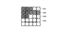
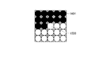
図13は、A*BマトリックスのRGB画素データの一例を示す図である。図14は、N*Mマトリックスの文字形状データの一例を示す図である。図13に示すA*BマトリックスのRGB画素データは、右上の2画素に赤(R)の画素1301、および注目画素1302に隣接する画素範囲1303に青(B)の画素1304を有する例である。図14に示すN*Mマトリックスの文字形状データは、図13に示す青(B)の画素1304が文字画素(黒の画素)1402であり、図13に示す赤(R)の画素1301が文字画素以外の画素(白の画素)1401)である例である。文字判定色装置1205は、図13に示すA*BマトリックスのRGB画素データおよび図14に示すN*Mマトリックスの文字形状データを受け取った場合、青(B)の画素1304が注目画素1302に隣接しかつ文字画素1402であることを示しているので、青(B)を文字画素のRGB画素データと判定する。
FIG. 13 is a diagram illustrating an example of RGB pixel data of an A * B matrix. FIG. 14 is a diagram illustrating an example of character shape data of an N * M matrix. The RGB pixel data of the A * B matrix shown in FIG. 13 is an example in which the upper right two pixels have red (R)
そして、文字色判定装置1205は、図13に示すA*BマトリックスのRGB画素データにおいて青(B)を示し、かつ図14に示すN*Mマトリックスの文字形状データにおいて文字画素1402であることを示す画素の配置を表すマッチングパターンを生成する。なお、文字色判定装置1205は、図13に示すA*BマトリックスのRGB画素データおよび図14に示すN*Mマトリックスの文字形状データを受け取った場合、図14に示すN*Mマトリックスの文字形状データと同様のマッチングパターンを生成する。
Then, the character
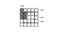
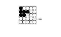
図15は、A*BマトリックスのRGB画素データの他の例を示す図である。図16は、N*Mマトリックスの文字形状データの他の例を示す図である。図17は、生成されたマッチングパターンの一例を示す図である。図15に示すA*BマトリックスのRGB画素データは、赤(R)の画素1501および青(B)の画素1502をそれぞれ同じ数有し、注目画素1503に隣接する画素範囲1504では青(B)の画素1502が支配的である例である。図16に示すN*Mマトリックスの文字形状データは、図15に示す赤(R)の画素1501および青(B)の画素1502が共に文字画素1601である例である。
FIG. 15 is a diagram illustrating another example of RGB pixel data of an A * B matrix. FIG. 16 is a diagram illustrating another example of character shape data of an N * M matrix. FIG. 17 is a diagram illustrating an example of the generated matching pattern. The RGB pixel data of the A * B matrix shown in FIG. 15 has the same number of red (R)
ここで、文字色判定装置1205は、図15に示すA*BマトリックスのRGB画素データおよび図16に示すN*Mマトリックスの文字形状データを受け取った場合、赤(R)の画素1501および青(B)の画素1502が共に注目画素1503に隣接し、さらに赤(R)の画素1501および青(B)の画素1502が共に文字画素1601であることを示しているので、画素範囲1504で支配的な青(B)の画素1502が示す青(B)を文字画素のRGB画素データと判定する。
When the character
そして、文字色判定装置1205は、図15に示すA*BマトリックスのRGB画素データにおいて青(B)を示し、かつ図16に示すN*Mマトリックスの文字形状データにおいて文字画素であることを示す画素の配置を表すマッチングパターン(図17に示す)を生成する。
The character
パターンアドレス生成装置1206は、文字色判定装置1205で生成されたN*Mマトリックスのマッチングパターンを用いて、マッチングパターン記憶装置805から当該N*Mマトリックスと一致する所定のマッチングパターンを見つけ出す。そして、パターアドレス生成装置1206は、見つけ出した所定のマッチングパターンと対応付けて記憶される配置データのマッチングパターン記憶装置805上でのアドレスを求めて、求めたアドレスに記憶されている配置データをマッチングパターン記憶装置805から出力する。
The pattern
Delayメモリ1207は、マッチングパターン記憶装置805から出力される配置データに合せて、2*2拡大装置1208へのRGB画素データの入力を遅らせるものである。
The
2*2拡大装置1208は、注目画素のRGB画素データを2*2倍して下地認識装置1209に入力するものである。
The 2 * 2
下地認識装置1209は、2*2拡大装置1208により2*2倍した注目画素が下地であるか否か(白の画素であるか否か)を認識し、下地である場合には、マッチングパターン記憶装置805から出力された配置データが表す文字画素の配置に従って、当該2*2倍した注目画素を、文字画素のRGB画素データで補間する。なお、本実施の形態では、注目画素が下地である場合にのみ、補間を行っているが、これに限定するものではなく、注目画素が下地でない場合であっても補間を行っても良い。
The
ただし、注目画素が文字形状以外の他の形状に含まれている場合、当該注目画素の補間だけでは、RGB画素データを高解像度の画像に変換することができない。また、文字形状の周囲に様々な色が存在する場合、文字を高解像度にしても画質が向上せず、間違った画像が生成されることもある。そのため、注目画素が下地である場合にのみ、補間を行うことが好ましい。 However, when the target pixel is included in a shape other than the character shape, RGB pixel data cannot be converted into a high-resolution image only by interpolation of the target pixel. Also, when there are various colors around the character shape, even if the character has a high resolution, the image quality is not improved and an incorrect image may be generated. Therefore, it is preferable to perform interpolation only when the target pixel is the background.
図18は、補間後のA*BマトリックスのRGB画素データの一例を示す図である。文字色判定装置1205が図13に示すRGB画素データおよび図14に示す文字形状データを受け取った場合、下地認識装置1209は、図18に示すように、マッチングパターン記憶装置805から出力される図10に示す配置データが表す文字画素の配置に従って、図15に示すA*BマトリックスのRGB画素データに含まれる注目画素1503を2*2倍した画素を、文字画素のRGB画素データで補間する。
FIG. 18 is a diagram illustrating an example of RGB pixel data of the A * B matrix after interpolation. When the character
一方、文字色判定装置1205が図15に示すA*BマトリックスのRGB画素データおよび図16に示すN*Mマトリックスの文字形状データを受け取った場合、下地認識装置1209は、マッチングパターン記憶装置805から出力される図11に示す配置データが文字形状を表さないので、補間を行わない。
On the other hand, when the character
RGBラインメモリコントローラ1210は、下地認識装置1209により補間した2*2画素を受け取り、受け取った2*2画素の2*1画素をRGB1ラインメモリ1211に格納し、他の2*1画素を色変換処理装置815に転送する。
The RGB
図19は、解像度変換処理の手順を示すフローチャートである。まず、文字形状データ読み込み装置812が、メインメモリ114上の文字形状バンド画像メモリ格納領域から水平ライン方向にNライン分の文字形状データを読み込み、文字形状Mラインメモリ1201に書き込む(ステップS1901)。さらに、RGB画素データ読み込み装置810が、メインメモリ114上のRGBバンド画像メモリ格納領域から、Bライン分のRGB画素データを読み込み、RGB Bラインメモリ1203に書き込む(ステップS1902)。
FIG. 19 is a flowchart showing the procedure of resolution conversion processing. First, the character shape
次に、文字形状N*Mマトリックス切り出し装置1202が、文字形状Mラインメモリ1201に記憶されたNライン分の文字形状データから、注目画素を中心とするN*Mマトリックスの文字形状データを切り出す(ステップS1903)。さらに、RGB A*Bマトリックス切り出し装置1204が、RGB Bラインメモリ1203に記憶されたBライン分のRGB画素データから、注目画素を中心とするA*BマトリックスのRGB画素データを切り出す(ステップS1904)。
Next, the character shape N * M
文字色判定装置1205は、N*Mマトリックスの文字形状データおよびA*BマトリックスのRGB画素データを受け取り、注目画素に隣接し、かつ文字形状データが文字画素である画素のRGB画素データを文字画素のRGB画素データと判定し、判定したRGB画素データと同じ色でありかつ文字画素であることを示す画素の配置を表すN*Mマトリックスのマッチングパターンを求める(ステップS1905)。
The character
パターンアドレス生成装置1206は、生成されたN*Mマトリックスのマッチングパターンを用いて、マッチングパターン記憶装置805にアクセスし、当該N*Mマトリックスのマッチングパターンと一致する所定のマッチングパターンを見つけ出し、当該所定のマッチングパターンに含まれる注目画素を2*2倍したときの配置データを求める(ステップS1906)。
The pattern
2*2拡大装置1208は、注目画素のRGB画素データを2*2倍して下地認識装置1209に転送する(ステップS1907)。
The 2 * 2
下地認識装置1209は、2*2拡大装置1208により2*2倍した注目画素のRGB画素データが下地の白であるか判定し、白であれば2*2倍した注目画素を文字画素のRGB画素データで補間してRGBメモリコントローラ1210に転送し、白でなければ2*2倍した注目画素をそのままRGBメモリコントローラ1210に転送する(ステップS1908)。
The
RGBメモリコントローラ1210は、注目画素を2*2倍した2*2画素を受け取り、下の2*1画素をRGB1ラインメモリ1211へ書き込み、上の2*1画素を色変換処理装置815に転送する(ステップS1909)。
The
解像度変換装置814は、メインメモリ114上のRGBバンド画像メモリ格納領域に記憶されている1ライン分のRGB画素データに含まれる各画素の拡大処理が終了するまで上述の処理を繰り返す(ステップS1910:No)。
The
そして、1ライン分のRGB画素データに含まれる各画素の拡大処理が終了すると(ステップS1910:Yes)、RGBメモリコントローラ1210は、RGB1ラインメモリ1211から順次2*1画素を読み込み、色変換処理装置815に転送する(ステップS1911)。
When the enlargement processing of each pixel included in the RGB pixel data for one line is completed (step S1910: Yes), the
RGBメモリコントローラ1210は、RGB1ラインメモリ1211からの2*1画素の読み込みおよび色変換処理装置815への転送を1ライン分繰り返す(ステップS1912:No)。
The
そして、解像度変換装置814は、1ライン分の色変換処理装置815への転送が終了すると(ステップS1912:Yes)、1バンド分のRGB画素データの拡大処理が終了するまで、上述の処理を繰り返す(ステップS1913:No)。そして、解像度変換装置814は、1バンド分のRGB画素データの拡大処理が終了すると(ステップS1913:Yes)、1ページ分のRGB画素データの拡大処理が終了するまで、上述の処理を繰り返す(ステップS1914:No)。そして、解像度変換装置814は、1ページ分のRGB画素データの拡大処理が終了すると(ステップS1914:Yes)、拡大処理を終了する。
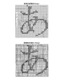
Then, when the transfer to the color
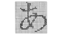
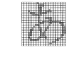
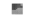
図20は、解像度変換前のRGB画素データと解像度変換後のRGB画素データの一例を示す図である。本実施の形態にかかる解像度変換装置814によれば、図20に示すように、解像度変換前の画像に含まれる文字画像が白黒以外の中間調で表現されている場合であっても、解像度変換した画像に含まれる文字画像の階段状の部分を滑らかにすることができる。
FIG. 20 is a diagram illustrating an example of RGB pixel data before resolution conversion and RGB pixel data after resolution conversion. According to the
このように、本実施の形態にかかる多色画像形成装置によれば、注目画素に隣接しかつ文字形状データが文字画素であることを示す画素のRGB画素データを文字画素のRGB画素データと判定し、RGB画素データが当該文字画素のRGB画素データでありかつ文字形状データが文字画素であることを示す画素の配置を表すマッチングパターンを生成し、生成したマッチングパターンが所定のマッチングパターンと一致した場合、当該所定のマッチングパターンに含まれる注目画素に拡大処理を実行した場合の文字画素の配置に従って、拡大処理を実行した注目画素を、文字画素のRGB画素データで補間することにより、文字画像に含まれる画素の色が中間調である場合であっても、文字の輪郭部の階段状の部分を補間することができるので、中間調のドットを含む画像においても、当該画像に含まれる文字画像を高解像度な形状に保つことができる。 As described above, according to the multicolor image forming apparatus according to the present embodiment, the RGB pixel data of the pixel adjacent to the target pixel and indicating that the character shape data is the character pixel is determined as the RGB pixel data of the character pixel. Then, a matching pattern representing the pixel arrangement indicating that the RGB pixel data is the RGB pixel data of the character pixel and the character shape data is the character pixel is generated, and the generated matching pattern matches the predetermined matching pattern. In this case, according to the arrangement of the character pixel when the enlargement process is performed on the target pixel included in the predetermined matching pattern, the target pixel that has been subjected to the enlargement process is interpolated with the RGB pixel data of the character pixel, thereby obtaining a character image. Even if the color of the included pixels is halftone, it is possible to interpolate the stepped portion of the outline of the character In, even in an image including a halftone dot, it is possible to keep the character images included in the image in high resolution shape.
なお、本実施の形態では、RGB画素データに対して画像処理を行う例について説明したが、多値画像のデータであれば、これに限定されるものではなく、同様に画像処理を行うことができる。例えば、CMY,CMYK、L*a*b*などで表現される多値画像のデータや、CMYのC版のみなど、1つの版で表される多値画像のデータ、RGBのRのみの多値画像のデータなどにも同様に画像処理を行うことができる。 In this embodiment, an example in which image processing is performed on RGB pixel data has been described. However, the present invention is not limited to this as long as it is multi-valued image data, and image processing can be similarly performed. it can. For example, multi-value image data expressed in CMY, CMYK, L * a * b *, etc., multi-value image data expressed in one version, such as only CMY C version, RGB only R Image processing can be similarly performed on value image data and the like.
105 描画装置
110 画像処理装置
814 解像度変換装置
1201 文字形状Mラインメモリ
1202 文字形状N*Mマトリックス切り出し装置
1203 RGB Bラインメモリ
1204 RGB A*Bマトリックス切り出し装置
1205 文字色判定装置
1206 パターンアドレス生成装置
1208 2*2拡大装置
1209 下地認識装置
DESCRIPTION OF
Claims (7)
生成した各画素の前記色画素データに拡大処理を実行する拡大手段と、
生成した前記文字形状データおよび前記色画素データに基づいて、拡大処理を実行した注目画素に隣接しかつ前記文字形状データが前記文字画素であることを示す画素の前記色画素データを前記文字画素の色画素データと判定し、前記色画素データが前記文字画素の色画素データでありかつ前記文字形状データが前記文字画素であることを示す画素の配置を表すマッチングパターンを生成する判定手段と、
前記文字画像に含まれる前記文字画素の配置を表す所定のマッチングパターンと、生成したマッチングパターンと、が一致した場合、当該所定のマッチングパターンに画素に拡大処理を実行した場合の前記文字画素の配置を表す配置データを生成する生成手段と、
生成した前記配置データが表す前記文字画素の配置に従って、拡大処理を実行した前記注目画素を、前記文字画素の色画素データで補間する補間手段と、
を備えたことを特徴とする画像処理装置。 Drawing means for generating color pixel data of each pixel in an image including a character image and character shape data indicating whether each pixel is a character pixel included in the character image;
Enlargement means for executing enlargement processing on the color pixel data of each pixel generated;
Based on the generated character shape data and the color pixel data, the color pixel data of a pixel adjacent to the target pixel on which the enlargement process has been performed and indicating that the character shape data is the character pixel Determining means for determining color pixel data, and generating a matching pattern representing an arrangement of pixels indicating that the color pixel data is color pixel data of the character pixel and the character shape data is the character pixel;
When the predetermined matching pattern representing the arrangement of the character pixels included in the character image matches the generated matching pattern, the arrangement of the character pixels when the pixel is enlarged to the predetermined matching pattern Generating means for generating arrangement data representing
Interpolating means for interpolating the pixel of interest subjected to the enlargement processing with the color pixel data of the character pixel according to the arrangement of the character pixel represented by the generated arrangement data;
An image processing apparatus comprising:
前記第1記憶手段から第1画素範囲の前記文字形状データを切り出す第1切出手段と、をさらに備え、
前記判定手段は、前記色画素データが前記文字画素の色画素データでありかつ前記文字形状データが前記文字画素であることを示す画素の配置を示す前記第1画素範囲の前記マッチングパターンを生成することを特徴とする請求項1に記載の画像処理装置。 Of the generated character shape data, first storage means for storing the character shape data for the first number of lines;
First cutout means for cutting out the character shape data in the first pixel range from the first storage means,
The determination unit generates the matching pattern in the first pixel range indicating an arrangement of pixels indicating that the color pixel data is color pixel data of the character pixel and the character shape data is the character pixel. The image processing apparatus according to claim 1.
前記第2記憶手段から第2画素範囲の前記色画素データを切り出す第2切出手段と、をさらに備え、
前記判定手段は、生成した前記文字形状データおよび前記第2画素範囲の前記色画素データに基づいて、前記注目画素に隣接しかつ前記文字形状データが前記文字画素であることを示す画素の前記色画素データを前記文字画素の色画素データと判定することを特徴とする請求項1から4のいずれか一に記載の画像処理装置。 Second storage means for storing the color pixel data for the second number of lines among the generated color pixel data;
A second cutout unit that cuts out the color pixel data in the second pixel range from the second storage unit;
The determination unit is configured to determine the color of a pixel adjacent to the target pixel and indicating that the character shape data is the character pixel based on the generated character shape data and the color pixel data of the second pixel range. The image processing apparatus according to claim 1, wherein pixel data is determined as color pixel data of the character pixel.
拡大手段が、生成した各画素の前記色画素データに拡大処理を実行する拡大工程と、
判定手段が、生成した前記文字形状データおよび前記色画素データに基づいて、拡大処理を実行した注目画素に隣接しかつ前記文字形状データが前記文字画素であることを示す画素の前記色画素データを前記文字画素の色画素データと判定し、前記色画素データが前記文字画素の色画素データでありかつ前記文字形状データが前記文字画素であることを示す画素の配置を表すマッチングパターンを生成する判定工程と、
生成手段が、前記文字画像に含まれる前記文字画素の配置を表す所定のマッチングパターンと、生成したマッチングパターンと、が一致した場合、当該所定のマッチングパターンに画素に拡大処理を実行した場合の前記文字画素の配置を表す配置データを生成する生成工程と、
補間手段が、生成した前記配置データが表す前記文字画素の配置に従って、拡大処理を実行した前記注目画素を、前記文字画素の色画素データで補間する補間工程と、
を有することを特徴とする画像処理装置の画像処理方法。 A drawing step in which drawing means generates color pixel data of each pixel in an image including a character image and character shape data indicating whether each pixel is a character pixel included in the character image;
An enlarging step in which an enlarging unit executes an enlarging process on the color pixel data of each pixel generated
Based on the character shape data and the color pixel data generated by the determination unit, the color pixel data of a pixel adjacent to the target pixel on which the enlargement process has been performed and indicating that the character shape data is the character pixel is obtained. Determination to determine color pixel data of the character pixel, and to generate a matching pattern indicating an arrangement of pixels indicating that the color pixel data is the color pixel data of the character pixel and the character shape data is the character pixel Process,
When the predetermined matching pattern representing the arrangement of the character pixels included in the character image matches the generated matching pattern, the generation unit performs the enlargement process on the pixel according to the predetermined matching pattern. A generation step of generating arrangement data representing the arrangement of character pixels;
An interpolation step in which the interpolation means interpolates the pixel of interest subjected to the enlargement process with the color pixel data of the character pixel according to the arrangement of the character pixel represented by the generated arrangement data;
An image processing method for an image processing apparatus, comprising:
Priority Applications (1)
| Application Number | Priority Date | Filing Date | Title |
|---|---|---|---|
| JP2008316083A JP2010141607A (en) | 2008-12-11 | 2008-12-11 | Image processor, and image processing method for same |
Applications Claiming Priority (1)
| Application Number | Priority Date | Filing Date | Title |
|---|---|---|---|
| JP2008316083A JP2010141607A (en) | 2008-12-11 | 2008-12-11 | Image processor, and image processing method for same |
Publications (1)
| Publication Number | Publication Date |
|---|---|
| JP2010141607A true JP2010141607A (en) | 2010-06-24 |
Family
ID=42351339
Family Applications (1)
| Application Number | Title | Priority Date | Filing Date |
|---|---|---|---|
| JP2008316083A Pending JP2010141607A (en) | 2008-12-11 | 2008-12-11 | Image processor, and image processing method for same |
Country Status (1)
| Country | Link |
|---|---|
| JP (1) | JP2010141607A (en) |
Cited By (1)
| Publication number | Priority date | Publication date | Assignee | Title |
|---|---|---|---|---|
| CN112699886A (en) * | 2020-12-30 | 2021-04-23 | 广东德诚大数据科技有限公司 | Character recognition method and device and electronic equipment |
-
2008
- 2008-12-11 JP JP2008316083A patent/JP2010141607A/en active Pending
Cited By (2)
| Publication number | Priority date | Publication date | Assignee | Title |
|---|---|---|---|---|
| CN112699886A (en) * | 2020-12-30 | 2021-04-23 | 广东德诚大数据科技有限公司 | Character recognition method and device and electronic equipment |
| CN112699886B (en) * | 2020-12-30 | 2024-06-11 | 广东德诚科教有限公司 | Character recognition method and device and electronic equipment |
Similar Documents
| Publication | Publication Date | Title |
|---|---|---|
| JP4979357B2 (en) | Image forming apparatus and control method thereof | |
| JP2013084224A (en) | Image forming apparatus | |
| JP2007282240A (en) | Bitmapped based trapping method and print system | |
| US8786901B2 (en) | Image processing apparatus, image processing method, and computer program product | |
| JP2012100240A (en) | Image processing device, and image processing method | |
| JP2009290612A (en) | Image processing device, image processing method and image forming apparatus | |
| JP5404340B2 (en) | Image forming apparatus, image forming method, and program | |
| JP6630086B2 (en) | Image processing apparatus, image processing method, and program | |
| JP2010141607A (en) | Image processor, and image processing method for same | |
| CN114945060B (en) | Image processing apparatus and image forming apparatus | |
| JP7599878B2 (en) | Image forming device | |
| US20050286087A1 (en) | Image outputting system, image outputting method, program for executing the method and a computer-readable information recording medium on which the program is recorded | |
| JP2008147748A (en) | Image processor and image processing method | |
| US7460274B2 (en) | Controlling apparatus for outputting processed image data | |
| JP5419608B2 (en) | Image forming apparatus and image forming method | |
| US10578994B2 (en) | Image forming apparatus that determines a fixing temperature for a fixing operation based on toner amounts of blocks of image data and related image forming method and storage medium | |
| JP5644230B2 (en) | Image processing apparatus and image processing method | |
| JP5740991B2 (en) | Image processing apparatus and image processing method | |
| JP2009169727A (en) | Image processing apparatus, image processing method, and program | |
| JP2013164557A (en) | Image forming control device, image forming control method, and image forming control program | |
| US8149457B2 (en) | Image forming apparatus, image forming method, and computer readable medium recording a printing data generation program | |
| JP7516908B2 (en) | Image forming apparatus, image forming method, and program | |
| JP5459000B2 (en) | Image processing apparatus and program | |
| JP5262882B2 (en) | Image processing apparatus and image processing method | |
| JP4894588B2 (en) | Image processing apparatus, printing apparatus, and image processing program |