JP2010141945A - Geared motor - Google Patents
Geared motor Download PDFInfo
- Publication number
- JP2010141945A JP2010141945A JP2008312975A JP2008312975A JP2010141945A JP 2010141945 A JP2010141945 A JP 2010141945A JP 2008312975 A JP2008312975 A JP 2008312975A JP 2008312975 A JP2008312975 A JP 2008312975A JP 2010141945 A JP2010141945 A JP 2010141945A
- Authority
- JP
- Japan
- Prior art keywords
- gear
- face
- motor
- output shaft
- geared motor
- Prior art date
- Legal status (The legal status is an assumption and is not a legal conclusion. Google has not performed a legal analysis and makes no representation as to the accuracy of the status listed.)
- Granted
Links
Images

Landscapes
- Gear Transmission (AREA)
- Connection Of Motors, Electrical Generators, Mechanical Devices, And The Like (AREA)
Abstract
Description
本発明は、モータの出力軸と歯車減速機の入力軸とが食い違う方向に配設されたギヤードモータに関わり、特に歯車減速機の初段歯車にフェースギヤを用いたギヤードモータに関する。 The present invention relates to a geared motor in which an output shaft of a motor and an input shaft of a gear reducer are arranged in a direction that is different, and more particularly to a geared motor using a face gear as a first gear of a gear reducer.
電動モータの出力軸と直交する方向あるいは食い違う方向に動力を取り出すためにフェースギヤあるいはハイポイドギヤを用いた歯車減速機が知られている。
フェースギヤは平歯車または、はすば歯車と噛み合う円盤状の歯車で、直交する軸または食い違い軸に使われている。
一方、ハイポイドギヤは食い違い軸の間に運動を伝達する円錐状の歯車で、大小歯車の軸がオフセットされていて、まがりばかさ歯車に似た歯車である。
従来のフェースギヤを用いた直交型ギヤードモータとしては、たとえば特許文献1,2が知られている。
A gear reducer that uses a face gear or a hypoid gear to extract power in a direction perpendicular to or different from the output shaft of an electric motor is known.
The face gear is a spur gear or a disc-shaped gear that meshes with a helical gear, and is used for an orthogonal axis or a staggered axis.
On the other hand, a hypoid gear is a conical gear that transmits motion between staggered shafts, and is a gear similar to a spiral bevel gear with the shafts of large and small gears offset.
For example,
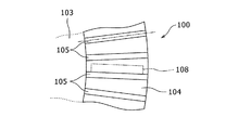
従来から用いられていたフェースギヤとして、図6に示すようなフェースギヤ100が知られている。このフェースギヤ100は、円板状に形成され、中心部には、フェースギヤ100を従動軸101に取付けるための取付孔102が設けられている。このフェースギヤ100の平坦面103の外縁部には、平坦面103から軸方向に突出する歯切部104が円環状に延びるように設けられている。この歯切部104には従動側噛合歯105が複数設けられている。この従動側噛合歯105は、フェースギヤ100の軸線と直交する方向へ延びている。
As a face gear conventionally used, a
前記従動軸101と直交する方向に延びる電動モータの出力軸106には、ピニオンとも呼ばれる平歯車107が取付けられ、平歯車107の外周面には、前記フェースギヤ100の従動側噛合歯105と噛み合う駆動側噛合歯108が複数設けられている。
A
電動モータの駆動により出力軸106が回転すると、図7に示すように平歯車107の駆動側噛合歯108が1つずつフェースギヤ100の各従動側噛合歯105に押し付けられ、フェースギヤ100が軸線を中心に回転する。
When the
ところが、上記フェースギヤ100では、平歯車107の各駆動側噛合歯108が1つずつフェースギヤ100における各従動側噛合歯105の1つ1つに押し付けられる。そのため、所定の駆動側噛合歯108が従動側噛合歯105に押し付けられてから、前記駆動側噛合歯108の隣に位置する駆動側噛合歯108が従動側噛合歯105に押し付けられるまでの間はフェースギヤ100の回転速度が遅くなる。そして、回転速度が遅くなったフェースギヤ100は、駆動側噛合歯108が従動側噛合歯105に押し付けられた時に回転速度が速くなる。したがって、フェースギヤ100の回転速度が遅くなったり速くなったりするため、フェースギヤ100を滑らかに回転させることができないという問題があった。
However, in the
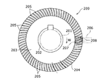
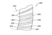
そこで、図8に示すように、外周面に対してそれぞれ等角度で傾斜している従動側噛合歯205を設けたフェースギヤ200が知られている。これら従動側噛合歯205は、矢印W方向へ向かって凸状となるように湾曲して形成されている。
そして、電動モータの出力軸206は、その軸線が従動軸201の軸線と直交する方向へ延びて従動軸201の軸線と交差するように配置されている。そして、フェースギヤ200の噛合歯205には電動モータの出力軸206に取り付けられた斜歯歯車207が噛合わされる。この斜歯歯車207の外周面には斜歯歯車207の軸線を中心に螺旋状に延びる複数の噛合歯208が設けられ、その噛合歯208が、図9に示すように、フェースギヤ200の噛合歯205に噛合って回転を伝達している(特許文献1参照)。
Therefore, as shown in FIG. 8, there is known a
The
また、特許文献2においても、直交する方向に配置されたフェースギヤとモータのヘリカルピニオンとの間で回転を伝達している。
このような従来のフェースギヤを用いた直交軸ギヤードモータでは、減速比を変更しようとしたときは、ピニオンとギヤの諸元を変更する、あるいはピニオンとギヤの位置関係を変更する必要があった。
ゆえに減速比を変更するには、モータピニオン又はギヤケースを新たに用意する必要があり、モータピニオンおよびギヤケースの両方を共用化した上で減速比を変更することはできないという問題点があった。
In such an orthogonal shaft geared motor using a conventional face gear, it is necessary to change the specifications of the pinion and the gear or to change the positional relationship between the pinion and the gear when changing the reduction ratio. .
Therefore, in order to change the reduction ratio, it is necessary to newly prepare a motor pinion or a gear case, and there is a problem that the reduction ratio cannot be changed after both the motor pinion and the gear case are shared.
本発明は、上記課題を解決し、モータの出力軸に設けられた円筒歯車と、それに噛み合うフェースギヤとの減速比を極めて容易に変更することができるギヤードモータを提供することを目的とする。
また、本発明は、初段減速比が異なり、かつオフセット量が2種類存在しても、フェースギヤの配置と向きを変更することによりモータとギヤケース部品の両方を共用できるようにし、部品点数を減少させることを目的とする。
An object of the present invention is to solve the above-described problems and to provide a geared motor that can very easily change a reduction ratio between a cylindrical gear provided on an output shaft of a motor and a face gear meshing with the cylindrical gear.
In addition, the present invention makes it possible to share both the motor and gear case parts by changing the arrangement and direction of the face gear even if the first stage reduction ratio is different and there are two types of offset amounts, and the number of parts is reduced. The purpose is to let you.
本発明は、上記課題を解決するため、出力軸に、はすば歯車を用いた円筒歯車を有するモータと、初段歯車として、前記はすば歯車に噛合するフェースギヤを備える歯車減速機とからなるギヤードモータにおいて、前記円筒歯車と前記初段歯車を、互いの軸が交差しないようにオフセットさせて噛合させ、前記初段歯車を、前記歯車減速機のケース内の異なる箇所に軸支可能に構成し、前記異なる箇所の軸支位置で、前記初段歯車として減速比の異なるフェースギヤを選択的に組み付け可能にしたことにある。
また、本発明は、前記各軸支位置から前記ケース内壁面との最短距離がそれぞれ異なるように設定し、前記各軸支位置に組付ける前記フェースギヤの径および歯数を選別して減速比を設定したことにある。
さらに、本発明は、前記出力軸を間に挟んで、前記異なる径のフェースギヤを前記各軸支位置に組付け可能に設定するとともに、前記フェースギヤの軸支位置によって、前記フェースギヤを逆向きに前記円筒歯車に噛合させたことにある。
またさらに、本発明は、前記モータの出力軸に設けられる円筒歯車に、前記歯車減速機の初段歯車の軸支位置および歯数に関係なく噛合可能な有効歯幅を設けたことにある。
In order to solve the above problems, the present invention includes a motor having a cylindrical gear using a helical gear as an output shaft, and a gear reducer including a face gear meshing with the helical gear as a first stage gear. In this geared motor, the cylindrical gear and the first gear are offset and meshed so that their axes do not cross each other, and the first gear is configured to be pivotally supported at different locations in the case of the gear reducer. Further, it is possible to selectively assemble face gears having different reduction ratios as the first-stage gears at the shaft support positions at the different locations.
Further, the present invention is set such that the shortest distances from the respective shaft support positions to the inner wall surface of the case are different from each other, and the reduction gear ratio is selected by selecting the diameter and the number of teeth of the face gear assembled to each of the shaft support positions. It is in having set.
Further, according to the present invention, the face gears having different diameters are set to be attachable to the respective pivot support positions with the output shaft interposed therebetween, and the face gears are reversed according to the pivot support positions of the face gears. It is in meshing with the cylindrical gear in the direction.
Still further, the present invention resides in that an effective tooth width capable of meshing is provided in a cylindrical gear provided on the output shaft of the motor regardless of the shaft support position and the number of teeth of the first stage gear of the gear reducer.
請求項1の発明によれば、減速比を極めて容易に変更することが可能なギヤードモータを得ることができる。そのため初段減速比を変更しても、モータとギヤケース部品の両方を共用できる設計が可能で、コスト削減が図れる。
請求項2の発明によれば、ケース内の有効利用が図れ、最大限の減速比を得ることができる。
請求項3の発明によれば、フェースギヤの軸支位置によって、前記フェースギヤを逆向きに組付けることで、フェースギヤに対する円筒歯車のオフセット方向を合わせることができる。
請求項4の発明によれば、歯数の異なるフェースギヤに対して共通に円筒歯車を噛合させることができる。
According to invention of
According to the invention of claim 2, effective use in the case can be achieved and the maximum reduction ratio can be obtained.
According to the invention of claim 3, the offset direction of the cylindrical gear with respect to the face gear can be matched by assembling the face gear in the reverse direction according to the axial support position of the face gear.
According to the invention of claim 4, the cylindrical gear can be meshed in common with the face gears having different numbers of teeth.
以下本発明の実施の形態を、図面を参照しながら詳細に説明する。
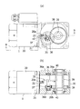
図1(a)(b)は、歯車減速機に採用される1段目の減速歯車の減速比を1/5にしたギヤードモータの例であり、図2(a)(b)は歯車減速機に採用される1段目の減速歯車の減速比を1/8にしたギヤードモータの例である。
Hereinafter, embodiments of the present invention will be described in detail with reference to the drawings.
FIGS. 1A and 1B are examples of a geared motor in which the reduction ratio of the first-stage reduction gear employed in the gear reducer is 1/5. FIGS. 2A and 2B are gear reductions. This is an example of a geared motor in which the reduction ratio of the first reduction gear employed in the machine is 1/8.
図1(a)(b)および図2(a)(b)において、1はギヤードモータで、このギヤードモータ1は、モータ20と歯車減速機30で構成されており、取付ボルト21を介してモータ20が歯車減速機30に組み付けられている。前記モータ20の出力軸20aには、ピニオンとして、はすば歯車を用いた円筒歯車22が一体または別体に設けられており、この円筒歯車22は一定の長さに設定されている。この実施の形態では円筒歯車22は、右ねじれのヘリカルギヤに加工されている。
In FIGS. 1A and 1B and FIGS. 2A and 2B,
図1(a)(b)の場合には、前記モータ20の出力軸20aは、歯車減速機30のケース31内に挿入され、歯車減速機30のケース31内に設けられた初段歯車としてのフェースギヤ(冠歯車とも言う。)32に前記円筒歯車22が噛合している。前記フェースギヤ32は、円盤状の本体の片面の周縁部に前記円筒歯車22のヘリカルギヤに噛み合う曲線状の歯面32aを環状に形成したもので、前記モータ20の出力軸20aと交差する軸として設けられた第1減速軸33に支持されている。この第1減速軸33は、前記歯車減速機30のケース31内に設けられた軸受け33a,33bを介して回転自在に支持されている。前記第1減速軸33は、モータ20の出力軸20aと直交する方向から一定幅e1、平行にオフセットさせた方向に配設されている。
前記第1減速軸33には、歯車34が装着されており、この歯車34に噛み合う歯車38が出力軸39に支持されている。この出力軸39は前記歯車減速機30のケース31内に設けられた軸受け39a,39bを介して回転自在に支持されている。出力軸39の両端部には、ケース31の内面との間をシールするオイルシール40が設けられている。
In the case of FIGS. 1A and 1B, the
A
図2(a)(b)の場合には、前記モータ20の出力軸20aは、歯車減速機30のケース31内に挿入され、歯車減速機30のケース31内に設けられた初段歯車としてのフェースギヤ(冠歯車とも言う。)35に前記円筒歯車22が噛合している。前記フェースギヤ35は、円盤状の本体の片面の周縁部に前記円筒歯車22のヘリカルギヤに噛み合う曲線状の歯面35aを環状に形成したもので、前記モータ20の出力軸20aと交差する軸として設けられた第1減速軸36に支持されている。この第1減速軸36は、前記歯車減速機30のケース31内に設けられた軸受け36a,36bを介して回転自在に支持されている。前記第1減速軸36は、モータ20の出力軸20aと直交する方向から一定幅e2、平行にオフセットさせた方向に配設されている。
前記第1減速軸36には、歯車37が装着されており、この歯車37に噛み合う歯車38が出力軸39に支持されている。この出力軸39は前記歯車減速機30のケース31内に設けられた軸受け39a,39bを介して回転自在に支持されている。出力軸39の両端部には、ケース31の内面との間をシールするオイルシール40が設けられている。
2 (a) and 2 (b), the
A
前記歯車減速機30のケース31は、ギヤケース31aとギヤフランジ31bで構成されている。前記モータ20の出力軸20aと直交する方向から一定幅e1、上方側に平行にオフセットさせた位置に、前記歯車減速機30の第1減速軸(入力軸)33を配設し、前記モータ20の出力軸20aを挟んで、第1減速軸(入力軸)33と反対側で、前記モータ20の出力軸20aと直行する方向から一定幅e2、下方側に平行にオフセットさせた位置に、前記歯車減速機30の第1減速軸(入力軸)36を配設している。こうして、前記モータ20の出力軸20aの回転を、出力軸20aから直交する方向、あるいは、出力軸20aを含む面と直交する方向に前記歯車減速機30の出力軸39から取り出すものである。
The case 31 of the
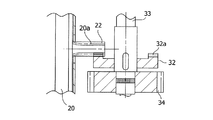
図1(a)(b)は1段目の減速比を1/5に設定したギヤードモータの例であり、図3に示すように、減速比1/5のときは、フェースギヤ32の外径が小さいため、モータ20の出力軸20aよりも上方側に配設している。第1減速軸33に装着する歯車34の径を大きくして歯車減速機30の出力軸39に装着された歯車38に噛合させている。そして、モータ20の出力軸20aに設けられた円筒歯車22にフェースギヤ32の歯面32aを噛合させている。
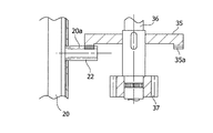
図2(a)(b)は1段目の減速比を1/8にしたギヤードモータの例であり、図4に示すように、減速比1/8のときは、フェースギヤ35の外径が大きくなるため、モータ20の出力軸20aよりも下方側に配設している。そして、モータ20の出力軸20aに設けられた円筒歯車22にフェースギヤ35の歯面35aを噛合させている。
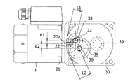
図5はモータ20の出力軸20aに設けられた円筒歯車22と、第1減速軸33、36との位置関係を示したもので、第1減速軸33、36に取り付けられるフェースギヤ32,35は、第1減速軸33、36の軸受け33a,33bおよび軸受け36a,36bが入るハウジング部が加工可能で、フェースギヤ32,35が収納可能なように、それぞれの減速比で適切なオフセット量e1,e2とギヤケース内壁31cまでの距離L1,L2を与えられて設計されている。
FIGS. 1A and 1B are examples of a geared motor in which the reduction ratio of the first stage is set to 1/5. As shown in FIG. 3, when the reduction ratio is 1/5, the outside of the
2 (a) and 2 (b) are examples of a geared motor in which the first stage reduction ratio is 1/8. As shown in FIG. 4, when the reduction ratio is 1/8, the outer diameter of the
FIG. 5 shows the positional relationship between the
歯車減速機30のケース31は、ギヤケース31aとギヤフランジ31bで構成されており、ギヤケース31の前後の内壁面31c、31dを上下方向に内側に向けて円弧状に湾曲させて形成されている。このギヤケース31の前側にモータ20が接続され、このモータ20側の内壁面31cに近接させてフェースギヤ32,35を配置するように構成されている。
A case 31 of the
次に、上記構成の減速歯車の初段の減速比を1/5にしたギヤードモータを使用する場合には、図1(a)(b)に示すように、フェースギヤ32を第1減速軸33に組み付けて使用する。第1減速軸33には、フェースギヤ32とともに歯車34を組付け、軸受け33a,33bを介してケース31に組付ける。そして、モータ20の出力軸20aに設けられた円筒歯車22にフェースギヤ32の歯面32aを噛合させ、第1減速軸33に組み付けられた歯車34を出力軸39に装着された歯車38に噛合させる。こうして、第1減速軸33には、フェースギヤ32によりモータ20の出力軸20aの回転を1/5に減速させて取り出すことができる。
Next, when using a geared motor in which the reduction gear ratio of the first stage of the above-described reduction gear is 1/5, the
また、上記構成の減速歯車の初段の減速比を1/8にしたギヤードモータを使用する場合には、図2(a)(b)に示すように、フェースギヤ35を第1減速軸36に組み付けて使用する。このとき、フェースギヤ35の向きはフェースギヤ32と逆向きにして組付ける。第1減速軸36には、フェースギヤ35とともに歯車37を組付け、軸受け36a,36bを介してケース31に組付ける。そして、モータ20の出力軸20aに設けられた円筒歯車22にフェースギヤ35の歯面35aを噛合させ、第1減速軸36に組み付けられた歯車37を出力軸39に装着された歯車38に噛合させる。こうして、第1減速軸33には、フェースギヤ35によりモータ20の出力軸20aの回転を1/8に減速させて取り出すことができる。
When a geared motor having a reduction gear ratio of 1/8 of the above-described reduction gear is used, the
そのときモータ20の出力軸20aとしての円筒歯車22は、フェースギヤ32、35の両方に噛み合うように十分な有効歯幅に設定する。
こうして、初段において異なる減速比を持ち、かつ異なるオフセット量が与えられている場合でも、モータ20、ギヤケース31a、ギヤフランジ31bを共用化することができる。
At that time, the
Thus, the
なお、本発明は上記実施の形態のみに限定されるものではなく、例えば、上記実施の形態では、2種類の異なるオフセット量が与えられているフェースギヤ32、35を用いて初段の減速比を1/5または1/8に減速させる例について説明したが、ギヤ比の異なるフェースギヤを用いることによって、初段の減速比を更に変えることができるのは勿論である。その他、本発明の要旨を変更しない範囲内で適宜変更して実施し得ることは言うまでもない。 Note that the present invention is not limited to the above embodiment. For example, in the above embodiment, the first stage reduction ratio is set using the face gears 32 and 35 to which two different offset amounts are given. Although the example of decelerating to 1/5 or 1/8 has been described, it is a matter of course that the first stage reduction ratio can be further changed by using face gears having different gear ratios. In addition, it cannot be overemphasized that it can change suitably and can implement within the range which does not change the gist of the present invention.
1 ギヤードモータ
20 モータ
20a 出力軸
22 円筒歯車
30 歯車減速機
31 ケース
31a ギヤケース
31b ギヤフランジ
32,35 フェースギヤ
33,36 第1減速軸
34、37,38 歯車
39 出力軸
DESCRIPTION OF
Claims (4)
4. The effective gear width according to claim 1, wherein the cylindrical gear provided on the output shaft of the motor is provided with an effective tooth width that can be engaged regardless of the shaft support position and the number of teeth of the first gear of the gear reducer. The geared motor according to claim 1.
Priority Applications (1)
| Application Number | Priority Date | Filing Date | Title |
|---|---|---|---|
| JP2008312975A JP4972630B2 (en) | 2008-12-09 | 2008-12-09 | Geared motor gear assembly method |
Applications Claiming Priority (1)
| Application Number | Priority Date | Filing Date | Title |
|---|---|---|---|
| JP2008312975A JP4972630B2 (en) | 2008-12-09 | 2008-12-09 | Geared motor gear assembly method |
Publications (2)
| Publication Number | Publication Date |
|---|---|
| JP2010141945A true JP2010141945A (en) | 2010-06-24 |
| JP4972630B2 JP4972630B2 (en) | 2012-07-11 |
Family
ID=42351570
Family Applications (1)
| Application Number | Title | Priority Date | Filing Date |
|---|---|---|---|
| JP2008312975A Active JP4972630B2 (en) | 2008-12-09 | 2008-12-09 | Geared motor gear assembly method |
Country Status (1)
| Country | Link |
|---|---|
| JP (1) | JP4972630B2 (en) |
Cited By (5)
| Publication number | Priority date | Publication date | Assignee | Title |
|---|---|---|---|---|
| JP2012184786A (en) * | 2011-03-03 | 2012-09-27 | Asmo Co Ltd | Compound planetary gear mechanism and speed reducing motor |
| JP2012219983A (en) * | 2011-04-13 | 2012-11-12 | Oriental Motor Co Ltd | Orthogonal axis geared motor |
| JP2013021809A (en) * | 2011-07-11 | 2013-01-31 | Oriental Motor Co Ltd | Geared motor |
| JP2015180186A (en) * | 2015-05-19 | 2015-10-08 | オリエンタルモーター株式会社 | geared motor |
| CN112211958A (en) * | 2019-07-09 | 2021-01-12 | 纳博特斯克有限公司 | Gear mechanism and speed reducer |
Citations (3)
| Publication number | Priority date | Publication date | Assignee | Title |
|---|---|---|---|---|
| JPS58100459U (en) * | 1981-12-28 | 1983-07-08 | 株式会社ボッシュオートモーティブ システム | motor actuator |
| JP2004266980A (en) * | 2003-03-04 | 2004-09-24 | Sumitomo Heavy Ind Ltd | Manufacturing method for hypoid geared motor and series thereof |
| JP2007074789A (en) * | 2005-09-05 | 2007-03-22 | Sumitomo Heavy Ind Ltd | Geared motor, and series of geared motors, and method of manufacturing geared motor |
-
2008
- 2008-12-09 JP JP2008312975A patent/JP4972630B2/en active Active
Patent Citations (3)
| Publication number | Priority date | Publication date | Assignee | Title |
|---|---|---|---|---|
| JPS58100459U (en) * | 1981-12-28 | 1983-07-08 | 株式会社ボッシュオートモーティブ システム | motor actuator |
| JP2004266980A (en) * | 2003-03-04 | 2004-09-24 | Sumitomo Heavy Ind Ltd | Manufacturing method for hypoid geared motor and series thereof |
| JP2007074789A (en) * | 2005-09-05 | 2007-03-22 | Sumitomo Heavy Ind Ltd | Geared motor, and series of geared motors, and method of manufacturing geared motor |
Cited By (5)
| Publication number | Priority date | Publication date | Assignee | Title |
|---|---|---|---|---|
| JP2012184786A (en) * | 2011-03-03 | 2012-09-27 | Asmo Co Ltd | Compound planetary gear mechanism and speed reducing motor |
| JP2012219983A (en) * | 2011-04-13 | 2012-11-12 | Oriental Motor Co Ltd | Orthogonal axis geared motor |
| JP2013021809A (en) * | 2011-07-11 | 2013-01-31 | Oriental Motor Co Ltd | Geared motor |
| JP2015180186A (en) * | 2015-05-19 | 2015-10-08 | オリエンタルモーター株式会社 | geared motor |
| CN112211958A (en) * | 2019-07-09 | 2021-01-12 | 纳博特斯克有限公司 | Gear mechanism and speed reducer |
Also Published As
| Publication number | Publication date |
|---|---|
| JP4972630B2 (en) | 2012-07-11 |
Similar Documents
| Publication | Publication Date | Title |
|---|---|---|
| JP4972630B2 (en) | Geared motor gear assembly method | |
| KR200450505Y1 (en) | reducer | |
| TWI656287B (en) | Planetary gear reducer | |
| CN107225595A (en) | The wrist structure of robot | |
| JP4923032B2 (en) | Geared motor | |
| JP2012112455A (en) | Orthogonal shaft geared motor | |
| JP5906764B2 (en) | Gear device | |
| JP2019163787A (en) | Gear transmission device | |
| JP5480845B2 (en) | Planetary gear mechanism | |
| JP2017007080A (en) | Processing device | |
| JP5395158B2 (en) | Geared motor | |
| JP5025222B2 (en) | Gear device | |
| JP2011080519A (en) | Fastening structure of output shaft and transmission part | |
| JP4768077B1 (en) | Pipe cutter | |
| JP6369274B2 (en) | Inscribed mesh planetary gear mechanism | |
| JP7445552B2 (en) | Manufacturing method of reducer and reducer series | |
| JP6484014B2 (en) | Gear reducer with integrated face gear and spur gear | |
| JP6783460B2 (en) | Axis crossing type gear device | |
| JP2018009638A (en) | Planetary gear device | |
| JP4648806B2 (en) | Planetary gear set | |
| CN217647635U (en) | Shaft type single-edge hob | |
| JP2008309172A (en) | Geared motor | |
| CN215890976U (en) | Hydraulic motor with speed reducer for rotation | |
| JP2015052378A (en) | Planetary gear unit | |
| JP6240330B2 (en) | Gear box |
Legal Events
| Date | Code | Title | Description |
|---|---|---|---|
| A977 | Report on retrieval |
Free format text: JAPANESE INTERMEDIATE CODE: A971007 Effective date: 20110217 |
|
| A131 | Notification of reasons for refusal |
Free format text: JAPANESE INTERMEDIATE CODE: A131 Effective date: 20110401 |
|
| A521 | Request for written amendment filed |
Free format text: JAPANESE INTERMEDIATE CODE: A523 Effective date: 20110530 |
|
| A131 | Notification of reasons for refusal |
Free format text: JAPANESE INTERMEDIATE CODE: A131 Effective date: 20120106 |
|
| A521 | Request for written amendment filed |
Free format text: JAPANESE INTERMEDIATE CODE: A523 Effective date: 20120223 |
|
| TRDD | Decision of grant or rejection written | ||
| A01 | Written decision to grant a patent or to grant a registration (utility model) |
Free format text: JAPANESE INTERMEDIATE CODE: A01 Effective date: 20120313 |
|
| A01 | Written decision to grant a patent or to grant a registration (utility model) |
Free format text: JAPANESE INTERMEDIATE CODE: A01 |
|
| A61 | First payment of annual fees (during grant procedure) |
Free format text: JAPANESE INTERMEDIATE CODE: A61 Effective date: 20120409 |
|
| FPAY | Renewal fee payment (event date is renewal date of database) |
Free format text: PAYMENT UNTIL: 20150413 Year of fee payment: 3 |
|
| R150 | Certificate of patent or registration of utility model |
Ref document number: 4972630 Country of ref document: JP Free format text: JAPANESE INTERMEDIATE CODE: R150 Free format text: JAPANESE INTERMEDIATE CODE: R150 |
|
| R250 | Receipt of annual fees |
Free format text: JAPANESE INTERMEDIATE CODE: R250 |
|
| R250 | Receipt of annual fees |
Free format text: JAPANESE INTERMEDIATE CODE: R250 |
|
| R250 | Receipt of annual fees |
Free format text: JAPANESE INTERMEDIATE CODE: R250 |
|
| R250 | Receipt of annual fees |
Free format text: JAPANESE INTERMEDIATE CODE: R250 |
|
| R250 | Receipt of annual fees |
Free format text: JAPANESE INTERMEDIATE CODE: R250 |
|
| R250 | Receipt of annual fees |
Free format text: JAPANESE INTERMEDIATE CODE: R250 |
|
| R250 | Receipt of annual fees |
Free format text: JAPANESE INTERMEDIATE CODE: R250 |
|
| R250 | Receipt of annual fees |
Free format text: JAPANESE INTERMEDIATE CODE: R250 |
|
| R250 | Receipt of annual fees |
Free format text: JAPANESE INTERMEDIATE CODE: R250 |
|
| R250 | Receipt of annual fees |
Free format text: JAPANESE INTERMEDIATE CODE: R250 |
|
| R250 | Receipt of annual fees |
Free format text: JAPANESE INTERMEDIATE CODE: R250 |
|
| R250 | Receipt of annual fees |
Free format text: JAPANESE INTERMEDIATE CODE: R250 |