JP2010142271A - Bathtub with vertically long grip - Google Patents

Bathtub with vertically long grip Download PDF

Info

Publication number
JP2010142271A
JP2010142271A JP2008319628A JP2008319628A JP2010142271A JP 2010142271 A JP2010142271 A JP 2010142271A JP 2008319628 A JP2008319628 A JP 2008319628A JP 2008319628 A JP2008319628 A JP 2008319628A JP 2010142271 A JP2010142271 A JP 2010142271A
Authority
JP
Japan
Prior art keywords
grip
bathtub
vertically long
vertical
long grip
Prior art date
Legal status (The legal status is an assumption and is not a legal conclusion. Google has not performed a legal analysis and makes no representation as to the accuracy of the status listed.)
Pending
Application number
JP2008319628A
Other languages
Japanese (ja)
Inventor
Naoto Onishi
直人 大西
Current Assignee (The listed assignees may be inaccurate. Google has not performed a legal analysis and makes no representation or warranty as to the accuracy of the list.)
Inax Corp
Original Assignee
Inax Corp
Priority date (The priority date is an assumption and is not a legal conclusion. Google has not performed a legal analysis and makes no representation as to the accuracy of the date listed.)
Filing date
Publication date
Application filed by Inax Corp filed Critical Inax Corp
Priority to JP2008319628A priority Critical patent/JP2010142271A/en
Publication of JP2010142271A publication Critical patent/JP2010142271A/en
Pending legal-status Critical Current

Links

Images

Landscapes

  • Bathtubs, Showers, And Their Attachments (AREA)

Abstract

<P>PROBLEM TO BE SOLVED: To decrease the degree of pain and uncomfortableness of users Ma and Mb caused when abutted on a vertically long grip 13. <P>SOLUTION: In the bathtub 11 with the vertically long grip, the upper and lower connection parts 13b and 13b of the vertically long grip 13 are bonded to an erected surface 12a inside the bathtub, and the upper and lower connection parts 13b are extended from a long holding part 13a on the front side, which is long in the vertical direction, to the rear part for the vertically long grip 13. As for the vertically long grip 13, respective left and right outer side faces 13d and 13d extended from the holding part 13a to the upper and lower connection parts 13b and 13b are inclined such that the horizontal width dimension W from a virtual vertical center surface P passing through the horizontal middle of the left and right outer side faces vertically and antero-posteriorly to the respective outer side faces 13d is reduced from the rear part to the front part. <P>COPYRIGHT: (C)2010,JPO&INPIT

Description

本発明は、槽内の立面に縦長グリップを取り付けた縦長グリップ付き浴槽に関するものである。   The present invention relates to a bathtub with a vertically long grip in which a vertically long grip is attached to an elevation in a tank.

従来、縦長グリップ付き浴槽1は、図11(A)の正面図及び同図(B)の平面図に示す如く、浴槽本体2の左右及び上下の方向に延びる槽内の接合用立面2aに、縦長グリップ3の上下の接続部3b,3bを接合したものである(特許文献1)。この縦長グリップ3は、上下方向へ長い手前側の握り部3aから後方へ向かって上下の接続部3b,3bが延びて左右の外側面3c,3cが平行に形成され、左右幅寸法Wが上下方向及び前後方向の全域で同一となっている。
特開2003−310465の図4
Conventionally, as shown in the front view of FIG. 11 (A) and the plan view of FIG. 11 (B), the bathtub 1 with a vertically long grip is formed on the joining vertical surface 2a in the tank extending in the left and right and up and down directions of the bathtub body 2. The upper and lower connecting portions 3b and 3b of the vertically long grip 3 are joined (Patent Document 1). This vertically long grip 3 has upper and lower connecting portions 3b and 3b extending rearward from a grip portion 3a on the near side which is long in the vertical direction, and left and right outer surfaces 3c and 3c are formed in parallel, and the left and right width dimension W is vertical. It is the same in the entire direction and the front-rear direction.
FIG. 4 of JP2003-310465.

従来の縦長グリップ付き浴槽1は、浴槽内での左右位置の変更等のために体の向きを変更しようとする使用者Mbの腕等が槽内の立面2aに沿う左右方向へ移動中に縦長グリップ3の外側面3cに当接したり、膝を折曲げた座り姿勢で入浴している使用者Maの膝が槽内立面2aに沿う左右方向へ移動中に縦長グリップ3の外側面3cに当接したりすることがある。この場合、使用者Mbは、腕等の当接面を前後方向に対して傾斜させた状態となることが多いため、外側面3cの左右方向の広範囲で当接することなく、浴槽立面2aから離れたエッジ3c−1に局部的に当接させることが多くなり、痛みや不快感を生じることになる。   In the conventional bathtub 1 with a vertically long grip, the arm of the user Mb who wants to change the body direction for changing the left-right position in the bathtub or the like is moving in the left-right direction along the vertical surface 2a in the tank. The outer surface 3c of the vertically long grip 3 is moving while the knee of the user Ma bathing in the sitting posture in contact with the outer surface 3c of the vertically long grip 3 or bending the knee is moving along the standing surface 2a in the tank. Or may come into contact with. In this case, the user Mb is often in a state in which the contact surface such as an arm is inclined with respect to the front-rear direction. This often causes local contact with the separated edge 3c-1, which causes pain and discomfort.

本発明は、使用者が縦長グリップに当接するときに生じる痛さや不快の程度を緩和できるの縦長グリップ付き浴槽提供を目的とする。   An object of the present invention is to provide a bathtub with a vertically long grip that can alleviate the degree of pain and discomfort that occurs when a user comes into contact with the vertically long grip.

縦長グリップに当接するときに生じる使用者の痛さや不快の程度を緩和できるようにするために請求項1記載の本発明が採用した手段は、浴槽内の立面に縦長グリップの上下の接続部を接合し、縦長グリップが上下方向へ長い手前側の長い握り部から後方へ向かって上下の接続部を延ばした縦長グリップ付き浴槽において、縦長グリップは、握り部から上下の接続部にわたって延びる左右の各外側面が、左右外側面の左右中間を上下・前後へ通過する仮想垂直中心面から各外側面までの左右幅寸法を後方から前方へ向かって行く程に小さくなるように傾斜していることを特徴とする縦長グリップ付き浴槽である。   The means employed by the present invention according to claim 1 to relieve the pain and discomfort of the user that occurs when abutting the vertically long grip is provided by connecting the upper and lower connecting portions of the vertically long grip to the vertical surface of the bathtub. In a bathtub with a vertical grip, the vertical grip extends from the long grip on the front side, which is long in the vertical direction, to the rear, and the vertical grip is the left and right extending from the grip to the upper and lower connections. Each outer surface is inclined so that the left-right width dimension from the virtual vertical center plane passing through the left and right middle of the left and right outer surfaces in the up / down / front / rear direction to each outer surface becomes smaller as going from the rear to the front. This is a bathtub with a vertically long grip.

縦長グリップに当接するときに生じる使用者の痛さや不快の程度を緩和できるようにするために請求項2記載の本発明が採用した手段は、浴槽内の立面に縦長グリップの上下の接続部を接合し、縦長グリップが上下方向へ長い手前側の長い握り部から後方へ向かって上下の接続部を延ばした縦長グリップ付き浴槽において、縦長グリップは、浴槽内の立面の上下方向に沿って上方から下方へ正視したときの、握り部から上下の接続部にわたって延びる左右の各外側面と、浴槽本体に接合する接続部の接合面との外角が、90°を越えて120°以下(好ましくは、93°を越えて98°以下)の範囲で選択されていることを特徴とする縦長グリップ付き浴槽である。   In order to reduce the pain and discomfort of the user that occurs when contacting the vertically long grip, the means adopted by the present invention according to claim 2 is provided by connecting the upper and lower connecting portions of the vertically long grip to the vertical surface in the bathtub. In the bathtub with a vertical grip, the vertical grip extends along the vertical direction of the vertical surface in the bathtub. When viewed from the upper side to the lower side, the outer angle between the left and right outer surfaces extending from the grip part to the upper and lower connection parts and the joint surface of the connection part joined to the bathtub body exceeds 120 ° and is 120 ° or less (preferably Is a bathtub with a vertically long grip, which is selected in a range of more than 93 ° and not more than 98 °.

縦長グリップに当接するときに生じる使用者の痛さや不快の程度を更に緩和できるようにするために請求項3記載の本発明が採用した手段は、前記縦長グリップにおける左右の各外側面を、上下端から上下中央へ行く程に、左右外側面の左右中間を上下・前後へ通過する仮想垂直中心面へ向かって偏倚して連続的に凹むように湾曲させた請求項1又は2記載の縦長グリップ付き浴槽である。   In order to further reduce the degree of pain and discomfort of the user that occurs when abutting the vertically long grip, the means adopted by the present invention according to claim 3 is characterized in that the left and right outer surfaces of the vertically long grip are vertically moved. 3. A vertically long grip according to claim 1 or 2, wherein the longitudinal grip is curved so as to be continuously dented toward the virtual vertical center plane passing through the left and right middle of the left and right outer surfaces up and down and forward and backward as going from the end to the vertical center. It is a bathtub.

請求項1記載の本発明に係る縦長グリップ付き浴槽は、縦長グリップの左右の各外側面が仮想垂直中心面までの左右幅寸法を後方から前方へ向かって行く程に小さくなるように前後方向に対して傾斜しているので、縦長グリップの外側面と同様に前後方向に対して傾斜している使用者の腕等の当接面が縦長グリップの外側面に当接するとき、傾斜面どうしの面接触により単位面積当たりの当接力を小さくできると共に、使用者の当接面を縦長グリップの外側面で案内して前方へ向って移動させて縦長グリップから逃げ易くできるため、従来に比べて痛さや不快の程度を緩和できる。   The bathtub with a vertically long grip according to the first aspect of the present invention is configured so that the left and right outer surfaces of the vertically long grip become smaller in the left-right width dimension from the rear toward the front. When the abutment surface of the user's arm, etc., which is inclined with respect to the front-rear direction as well as the outer surface of the vertical grip, contacts the outer surface of the vertical grip, the surfaces of the inclined surfaces are inclined. The contact force per unit area can be reduced by contact, and the user's contact surface is guided by the outer surface of the vertically long grip and moved forward to facilitate escape from the vertically long grip. The degree of discomfort can be reduced.

請求項2記載の本発明に係る縦長グリップ付き浴槽は、左右の各外側面と浴槽本体に接合した接続部の接合面との外角を90°を越えて120°以下(好ましくは、93°を越えて98°以下)の範囲で選択して、左右の各外側面が前後方向に対して傾斜傾斜しているので、縦長グリップの外側面と同様に前後方向に対して傾斜している使用者の腕等の当接面が縦長グリップの外側面に当接するとき、傾斜面どうしの面接触により単位面積当たりの当接力を小さくできると共に、使用者の当接面を縦長グリップの外側面で案内して前方へ向って移動させて縦長グリップから逃げ易くできるため、従来に比べて痛さや不快の程度を緩和できる。   The bathtub with a vertically long grip according to the second aspect of the present invention has an outer angle between each of the left and right outer surfaces and the joint surface of the connecting portion joined to the bathtub body of more than 90 ° and 120 ° or less (preferably 93 °). Since the left and right outer surfaces are inclined with respect to the front-rear direction, the user is inclined with respect to the front-rear direction in the same manner as the outer surface of the vertical grip. When the abutment surface of the arm or the like abuts the outer surface of the vertical grip, the contact force per unit area can be reduced by the surface contact between the inclined surfaces, and the user's contact surface is guided by the outer surface of the vertical grip. And since it can move to the front and it is easy to escape from a vertically long grip, the degree of pain and discomfort can be relieved compared with the past.

請求項3記載の本発明に係る縦長グリップ付き浴槽は、使用者の腕等の当接面が縦長グリップの左右の外側面に当接するとき、凹むように湾曲した外側面に接触する面積が、縦長グリップの左右の外側面を湾曲させることなく直線状としたときに比べて大きくなり、痛さや不快さの程度を更に緩和できる。また、浴槽へ出入りする使用者が左右の外側面の湾曲部に頭を当てることことがあるが、このとき接触する面積が大きくなり、痛さや不快さの程度を更に緩和できる。   In the bathtub with a vertically long grip according to the present invention as defined in claim 3, when the contact surface of the user's arm or the like is in contact with the left and right outer surfaces of the vertically long grip, the area in contact with the outer surface curved so as to be recessed is Compared to the case where the left and right outer surfaces of the vertically long grip are made straight without bending, the degree of pain and discomfort can be further alleviated. Moreover, although the user who goes in and out of the bathtub may hit the head on the curved portions of the left and right outer surfaces, the contact area increases at this time, and the degree of pain and discomfort can be further alleviated.

本発明に係る縦長グリップ付き浴槽(以下、「本発明浴槽」と言う。)を図面に示す実施形態に基づいて説明する。   A bathtub with a vertically long grip according to the present invention (hereinafter referred to as “the present invention bathtub”) will be described based on an embodiment shown in the drawings.

(第1の実施の形態)
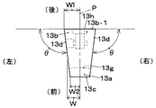
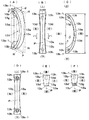
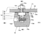
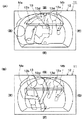
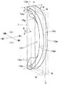
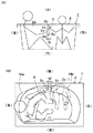
図1乃至図6は本発明浴槽の第1の実施の形態を示すものであり、図1は本発明浴槽11を示すものであって、(A)は平面図、(B)は(A)のイーイ線で断面した左側面図である。図2は浴槽本体2のグリップ接合用立面12a(鉛直方向V対して交差角度αで傾斜している)に沿って上方から下方へ正視したときの縦長グリップ13の平面図、図3は縦長グリップ13の接合状態を拡大して断面した左側面図である。図4は接合前の縦長グリップ13を単独で示すものであつて、(A)は斜視図、(B)は正面図、(C)は左側面図、(D)は背面図、(E)は平面図、(F)は(B)のハーハ線で断面した平面図である。図5は図3のローロ線で断面して拡大した平面図である。図6は大人と子供の二人の入浴状態を示す平面図であって、(A)は縦長グリップ13に子供Mbの腕が接触している状態を示し、(B)は縦長グリップ13に大人Maの腕が接触している状態を示している。
(First embodiment)
FIG. 1 thru | or FIG. 6 shows 1st Embodiment of this invention bathtub, FIG. 1 shows this invention bathtub 11, Comprising: (A) is a top view, (B) is (A). It is the left view which was cut in the Ea line. FIG. 2 is a plan view of the vertically long grip 13 when viewed from the upper side to the lower side along the grip joining vertical surface 12a of the bathtub body 2 (inclined at an intersecting angle α with respect to the vertical direction V), and FIG. It is the left view which expanded and joined the joining state of the grip 13. 4A and 4B show the longitudinal grip 13 before joining. FIG. 4A is a perspective view, FIG. 4B is a front view, FIG. 4C is a left side view, FIG. 4D is a rear view, and FIG. Is a plan view, and (F) is a plan view taken along the Haha line in (B). FIG. 5 is an enlarged plan view of the cross section taken along the roll line of FIG. FIG. 6 is a plan view showing a bathing state of two adults and a child, where (A) shows a state in which the arm of the child Mb is in contact with the longitudinal grip 13 and (B) shows an adult on the longitudinal grip 13. The state where Ma's arm is in contact is shown.

本発明浴槽11は、図1に示す如く、浴槽本体12の槽内の立面12aに縦長グリップ13の上下の接続部13b,13bを接合してある。浴槽本体12は、二人が入浴できる大きさに形成され(図6参照)、手前側から槽内へ出入りできるようになっていると共に、槽内後側のグリップ接合用立面12a側にステップ12bが設けられ、入浴時に腰掛け等できるようにしてある。本発明浴槽11は、立面12aが鉛直方向Vに対して交差角度αで傾斜することにより、縦長グリップ13も鉛直方向V対して交差角度αで傾斜している。なお、本発明浴槽11は、ステップ12bを設けない浴槽本体(図示略)に適用することも勿論可能である。   In the bathtub 11 of the present invention, as shown in FIG. 1, the upper and lower connecting portions 13 b and 13 b of the vertically long grip 13 are joined to the vertical surface 12 a in the tank of the bathtub body 12. The bathtub body 12 is formed in a size that allows two persons to take a bath (see FIG. 6), and can enter and exit from the front side into the tank, and is stepped toward the grip joining vertical surface 12a on the rear side in the tank. 12b is provided so that it can be seated when taking a bath. In the bathtub 11 of the present invention, the vertical surface 13 is inclined at the intersection angle α with respect to the vertical direction V because the elevation surface 12 a is inclined at the intersection angle α with respect to the vertical direction V. In addition, this invention bathtub 11 can also be applied to the bathtub main body (not shown) which does not provide step 12b.

前記縦長グリップ13は、図3及び図4に示す如く、合成樹脂やステンレススチール等の素材から成形され、上下方向へ長い手前側の長い握り部13aと、握り部13aから後方へ向かって延びる上下の接続部13b,13bを備え、握り部13aから上下の接続部13b,13bに至る手前表面13c及び左右の各外側面13dが弓状に湾曲形成されている。左右の各外側面13dは、両外側面13d,13dの左右中間を上下・前後へ通過する仮想垂直中心面P(図4(A)において一点鎖線で示す)から各外側面13dまでの左右幅寸法Wを後方から前方へ向かって行く程に小さくして、後方の左右幅寸法W1にすると共に手前の左右幅寸法W2となるように傾斜している。縦長グリップ13は、その大きさが例えば、接続部13bの接合面(浴槽本体12の立面12aに当接する面)13b−1の左右幅寸法(2・W1)が32〜36mm、上下の高さ寸法(H)が190〜210mm、前後奥行き寸法(D)が48〜54mmの範囲で選択され、また、本例では仮想垂直中心面Pを中心として左右対称に形成されている。   As shown in FIGS. 3 and 4, the vertically long grip 13 is formed of a material such as synthetic resin or stainless steel, and has a long grip portion 13a on the front side that is long in the vertical direction and an upper and lower portion that extends rearward from the grip portion 13a. The front surface 13c from the grip portion 13a to the upper and lower connection portions 13b, 13b and the left and right outer surfaces 13d are curved in a bow shape. Each of the left and right outer surfaces 13d has a lateral width from a virtual vertical center plane P (shown by a one-dot chain line in FIG. 4A) passing through the left and right middle of both outer surfaces 13d and 13d to the outer surfaces 13d. The dimension W is made smaller as it goes from the rear to the front, so that the left and right width dimension W1 on the rear side and the left and right width dimension W2 on the front side are inclined. The size of the vertically long grip 13 is, for example, a horizontal width dimension (2 · W1) of a joint surface (a surface that abuts the vertical surface 12a of the bathtub body 12) 13b-1 of the connection portion 13b is 32 to 36 mm, and a vertical height The length dimension (H) is selected in the range of 190 to 210 mm and the front and rear depth dimension (D) is in the range of 48 to 54 mm, and in this example, it is formed symmetrically about the virtual vertical center plane P.

前記縦長グリップ13は、浴槽本体12の傾斜する立面12aの上下方向に沿って上方から下方へ正視したとき、図2に示すように、左右の各外側面13dと接続部13bの接合面(浴槽本体12の立面12aに当接する面)13b−1との外角θが、90°を越えて120°以下(好ましくは、93°を越えて98°以下。更に好ましくは、95°前後)の範囲で選択されている。縦長グリップ13は、図4(A)に示す如く、左右の各外側面13dに仮想平坦面R(図中に破線で示す)を当接させたとき、各外側面13dの上下全域が仮想平坦面Rに当接し、仮想平坦面Rが接合面13b−1とを外角θで交差することになる。   When the vertically long grip 13 is viewed from the upper side to the lower side along the up-and-down direction of the inclined surface 12a of the bathtub body 12, as shown in FIG. 2, the left and right outer surfaces 13d are joined to the connecting portions 13b ( The external angle θ with respect to the vertical surface 12a of the bathtub body 12) 13b-1 exceeds 90 ° and is 120 ° or less (preferably more than 93 ° and 98 ° or less, more preferably around 95 °). Is selected in the range. As shown in FIG. 4A, the vertically long grip 13 has a virtual flat surface R (shown by a broken line in the drawing) in contact with the left and right outer surfaces 13d. The virtual flat surface R abuts on the surface R and intersects the bonding surface 13b-1 at an external angle θ.

前記縦長グリップ13は、図4に示す如く、握り部13aの裏側に、指挿入空間13fへ向かって突出する二辺からなる山状部13gが形成され、握り部13aの上下中間から各接合部13bへ向かって行く程に山状部13gの高さ寸法を大きくしてある。   As shown in FIG. 4, the vertically long grip 13 is formed with a mountain-shaped portion 13g composed of two sides protruding toward the finger insertion space 13f on the back side of the grip portion 13a. The height dimension of the mountain-shaped part 13g is enlarged so that it goes to 13b.

前記浴槽本体12に対する縦長グリップ13の接合は、図5に示す如く、接合手段14を用いて行なわれる。接合手段14は、雌ねじ15dが貫通した埋込用ピン部15a、フランジ部15b及びボルト部15cを同一中心線上に直列状に接合した接合具15と、ボルト部15cに螺着するナット16と、フランジ部15bに当接するシール用パッキン17と、縦長グリップ13の接合面13b−1に当接する取付用パッキン18と、固定用ネジ19とからなる。接合手段14は、縦長グリップ13の各接合面13b−1に凹設した接合用凹部13hに接合具15の埋込用ピン15a及びフランジ部15bを埋め込んで、接合具15の雌ねじ15dに固定用ネジ19を緊締することで、縦長グリップ13の各接続部13bに接合具15を固定すると共に、浴槽本体12に設けた取付孔12cへ挿通した接合具15のボルト部15cにナット16を緊締することで、浴槽本体12に接合具15を固定している。   The longitudinal grip 13 is joined to the bathtub body 12 by using joining means 14 as shown in FIG. The joining means 14 includes a joining tool 15 in which the embedding pin portion 15a through which the female screw 15d passes, the flange portion 15b, and the bolt portion 15c are joined in series on the same center line, and a nut 16 that is screwed to the bolt portion 15c. The seal packing 17 is in contact with the flange portion 15 b, the mounting packing 18 is in contact with the joint surface 13 b-1 of the vertically long grip 13, and the fixing screw 19. The joining means 14 is for fixing to the female screw 15d of the joining tool 15 by embedding the embedding pin 15a and the flange part 15b of the joining tool 15 in the joining recess 13h provided in each joining surface 13b-1 of the longitudinal grip 13. By tightening the screw 19, the joint 15 is fixed to each connection portion 13 b of the vertically long grip 13, and the nut 16 is fastened to the bolt portion 15 c of the joint 15 inserted into the mounting hole 12 c provided in the bathtub body 12. Thus, the connector 15 is fixed to the bathtub body 12.

本発明浴槽11は、図2及び図4に示す如く、縦長グリップ13の左右の各外側面13dが仮想垂直中心面Pまでの左右幅寸法Wを後方から前方へ向かって行く程に小さくなるように前後方向に対して傾斜すると共に、浴槽内の立面12aの上下方向に沿って上方から下方へ正視したときの、左右の各外側面13dと浴槽本体12に接合する接続部13の接合面13b−1との外角θが、90°を越えて120°以下(好ましくは、93°を越えて98°以下)の範囲で選択されているので、図6に示す如く、縦長グリップ13の外側面13dと同様に前後方向に対して傾斜している使用者Ma,Mbの腕等の当接面が縦長グリップ13の外側面13dに当接するとき、傾斜面どうしの面接触により単位面積当たりの当接力を小さくできると共に、使用者Ma,Mbの当接面を縦長グリップ13の外側面13dで案内して前方へ向って移動させて縦長グリップ13から逃げ易くできるため、従来に比べて痛さや不快の程度を緩和できる。   As shown in FIGS. 2 and 4, the bathtub 11 of the present invention is such that the left and right outer surfaces 13d of the vertically long grip 13 become smaller in the lateral width dimension W from the rear to the front toward the virtual vertical center plane P. The joint surface of each of the left and right outer surfaces 13d and the connecting portion 13 that joins the bathtub body 12 when viewed from the top to the bottom along the vertical direction of the vertical surface 12a in the bathtub. Since the external angle θ with respect to 13b-1 is selected in the range of more than 90 ° to 120 ° or less (preferably more than 93 ° to 98 ° or less), as shown in FIG. Similarly to the side surface 13d, when the contact surfaces such as the arms of the users Ma and Mb that are inclined with respect to the front-rear direction contact the outer surface 13d of the vertically long grip 13, the surface contact between the inclined surfaces per unit area The contact force can be reduced and Since the contact surfaces of the users Ma and Mb are guided by the outer side surface 13d of the vertically long grip 13 and moved forward to facilitate escape from the vertically long grip 13, the degree of pain and discomfort can be reduced as compared with the conventional case. .

(第2の実施の形態)
図7は第2の実施の形態に係る本発明浴槽に用いた縦長グリップ13を拡大して示す斜視図である。縦長グリップ13は、前記第1の実施の形態と同様に、縦長グリップ13の左右の各外側面13dが仮想垂直中心面Pまでの左右幅寸法Wを後方から前方へ向かって行く程に小さくなるように前後方向に対して傾斜すると共に、浴槽内の立面12aの上下方向に沿って上方から下方へ正視したときの、左右の各外側面13dと浴槽本体12に接合する接続部13の接合面(浴槽本体12の立面12aに当接する面)13b−1との外角θが、90°を越えて120°以下(好ましくは、93°を越えて98°以下)の範囲で選択されている。
(Second Embodiment)
FIG. 7 is an enlarged perspective view showing the vertically long grip 13 used in the bathtub of the present invention according to the second embodiment. In the same way as in the first embodiment, the vertical grip 13 becomes smaller as the left and right outer surfaces 13d of the vertical grip 13 go from the rear to the front in the left-right width dimension W up to the virtual vertical center plane P. Of the connecting portion 13 that joins the left and right outer side surfaces 13d and the bathtub body 12 when viewed from the top to the bottom along the vertical direction of the vertical surface 12a in the bathtub. The external angle θ with respect to the surface (surface that contacts the vertical surface 12a of the bathtub body 12) 13b-1 is selected in the range of more than 90 ° to 120 ° or less (preferably more than 93 ° to 98 ° or less). Yes.

本実施の形態に用いた縦長グリップ13において前記第1の実施の形態に用いたものと相違する点は、左右の各外側面13dを、上下端から上下中央へ行く程に、前記仮想垂直中心面P(図中に二点鎖線で示す)へ向かって偏倚して連続的に凹むように湾曲させたことである。本実施の形態に用いた縦長グリップ13は、左右の各外側面13dの上下全域に、相手方の外側面13dへ向かって凹む仮想彎曲面S(図中に破線で示す)を当接させたとき、仮想彎曲面Sと上下の接合面13b−1,13b−1を含む接合仮想面Tと外角θで交差するようになる。なお、本実施の形態に係る本発明浴槽における上記相違点以外の構成については、前記第1の実施の形態に係る本発明浴槽11と実質的に同一である。仮想彎曲面Sと仮想面Tとの外角θは、縦長グリップ13の上下全域で同一にする場合と、上下端から上下中央へ行く程に変化させる場合とを選択することができる。   The vertical grip 13 used in the present embodiment is different from that used in the first embodiment in that the virtual vertical center is increased from the upper and lower ends to the upper and lower centers of the left and right outer surfaces 13d. That is, it is curved toward the surface P (indicated by a two-dot chain line in the drawing) so as to be continuously depressed. When the vertically long grip 13 used in the present embodiment is in contact with a virtual saddle curved surface S (indicated by a broken line in the drawing) that is recessed toward the outer surface 13d of the other party, on the entire upper and lower sides of the left and right outer surfaces 13d. The virtual saddle curved surface S and the joint virtual surface T including the upper and lower joint surfaces 13b-1 and 13b-1 intersect at an outer angle θ. In addition, about structures other than the said difference in this invention bathtub which concerns on this Embodiment, it is substantially the same as this invention bathtub 11 which concerns on the said 1st Embodiment. The external angle θ between the virtual saddle curved surface S and the virtual surface T can be selected to be the same in the entire upper and lower regions of the vertically long grip 13 or to be changed from the upper and lower ends toward the upper and lower centers.

本実施の形態に係る本発明浴槽は、使用者Ma,Mb(図6参照)の腕等の当接面が縦長グリップ13の左右の外側面13dに当接するとき、凹むように湾曲した外側面13dに接触する面積が、縦長グリップ13dの左右の外側面13dを湾曲させることなく直線状とし第1の実施の形態に用いた縦長グリップ(図4(A)参照)に比べて大きくなり、痛さや不快さの程度を更に緩和できる。また、浴槽本体へ出入りする使用者が左右の外側面の湾曲部に頭を当てることことがある(殊に、高齢者ではお辞儀するような姿勢となって頭を当てることがある)が、このとき接触する面積が大きくなり、痛さや不快さの程度を更に緩和できる。   The bathtub of the present invention according to the present embodiment has an outer surface curved so as to be recessed when the contact surfaces of the arms of the users Ma and Mb (see FIG. 6) contact the left and right outer surfaces 13d of the vertically long grip 13. The area in contact with 13d becomes straight without bending the left and right outer surfaces 13d of the vertically long grip 13d, and becomes larger than the vertically long grip (see FIG. 4A) used in the first embodiment. The degree of sheath discomfort can be further alleviated. In addition, a user entering and exiting the bathtub body may hit his head on the curved parts of the left and right outer surfaces (especially, elderly people may bow in a bowing posture). Sometimes the contact area increases and the degree of pain and discomfort can be further alleviated.

(第3の実施の形態)
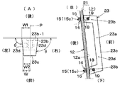
図8乃至図10は本発明浴槽の第3の実施の形態を示すものであって、図8(A)は浴槽本体2のグリップ接合用立面12a(鉛直方向V対して交差角度αで傾斜している)に沿って上方から下方へ正視したときの縦長グリップ23の平面図、図8(B)は縦長グリップ23の接合状態を拡大して断面した左側面図である。図9は接合前の縦長グリップ23を単独で示すものであつて、(A)は斜視図、(B)は正面図、(C)は背面図である。図10は縦長グリップ23の別態様を拡大して示す斜視図である。
(Third embodiment)
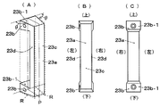
FIGS. 8 to 10 show a third embodiment of the bathtub of the present invention, and FIG. 8 (A) shows a grip joining vertical surface 12a of the bathtub body 2 (inclined at an intersecting angle α with respect to the vertical direction V). 8B is a plan view of the vertically long grip 23 when viewed from the top to the bottom along FIG. 8B, and FIG. 8B is a left side view in which the joining state of the vertically long grip 23 is enlarged and sectioned. FIGS. 9A and 9B show the vertically long grip 23 before joining. FIG. 9A is a perspective view, FIG. 9B is a front view, and FIG. 9C is a rear view. FIG. 10 is an enlarged perspective view showing another aspect of the vertically long grip 23.

本実施の形態の本発明浴槽21に用いた縦長グリップ23において前記第1の実施の形態に係る縦長グリップ13と相違する点は、握り部23aの手前表面23cを平坦面で形成したことである。なお、本実施の形態に係る本発明浴槽21における上記相違点以外の構成については、前記第1の実施の形態に係る本発明浴槽11と実質的に同一である。   The vertical grip 23 used in the bathtub 21 of the present embodiment is different from the vertical grip 13 according to the first embodiment in that the front surface 23c of the grip portion 23a is formed as a flat surface. . In addition, about structures other than the said difference in this invention bathtub 21 which concerns on this Embodiment, it is substantially the same as this invention bathtub 11 which concerns on the said 1st Embodiment.

前記縦長グリップ23は、合成樹脂やステンレススチール等の素材から成形され、上下方向へ長い手前側の長い握り部23aと、握り部23aから後方へ向かって延びる上下の接続部23b,23bを備え、握り部23aから上下の接続部23b,23bに至る左右の各外側面23dが略コ字状に形成されている。左右の各外側面23dは、両外側面23d,23dの左右中間を上下・前後へ通過する仮想垂直中心面P(図9(A)において一点鎖線で示す)から各外側面23dまでの左右幅寸法Wを後方から前方へ向かって行く程に小さくして、後方の左右幅寸法W1にすると共に手前の左右幅寸法W2となるように傾斜している。縦長グリップ23は、浴槽本体12の傾斜する立面12aの上下方向に沿って上方から下方へ正視したとき、図8(A)に示すように、左右の各外側面23dと接続部23bの接合面(浴槽本体12の立面12aに当接する面)23b−1との外角θが、90°を越えて120°以下(好ましくは、93°を越えて98°以下。更に好ましくは、95°前後)の範囲で選択されている。縦長グリップ23は、図9(A)に示す如く、左右の各外側面23dに仮想平坦面R(図中に破線で示す)を当接させたとき、各外側面23dの上下全域が仮想平坦面Rに当接し、仮想平坦面Rが接合面23b−1とを外角θで交差することになる。   The vertically long grip 23 is formed of a material such as synthetic resin or stainless steel, and includes a long grip portion 23a on the near side long in the vertical direction and upper and lower connection portions 23b and 23b extending rearward from the grip portion 23a. The left and right outer surfaces 23d extending from the grip portion 23a to the upper and lower connecting portions 23b, 23b are formed in a substantially U shape. Each of the left and right outer surfaces 23d has a horizontal width from a virtual vertical center plane P (shown by a one-dot chain line in FIG. 9A) passing through the middle between the left and right outer surfaces 23d and 23d in the vertical direction and the front and rear directions. The dimension W is made smaller as it goes from the rear to the front, so that the left and right width dimension W1 on the rear side and the left and right width dimension W2 on the front side are inclined. When the vertically long grip 23 is viewed from the upper side to the lower side along the up-and-down direction of the inclined vertical surface 12a of the bathtub body 12, as shown in FIG. 8 (A), the left and right outer side surfaces 23d are joined to the connecting portion 23b. The external angle θ with respect to the surface (surface that contacts the vertical surface 12a of the bathtub body 12) 23b-1 exceeds 90 ° and is 120 ° or less (preferably more than 93 ° and 98 ° or less. More preferably, 95 ° Is selected in the range of (before and after). As shown in FIG. 9A, the vertically long grip 23 has a virtual flat surface in the upper and lower regions of each outer surface 23d when the virtual flat surface R (shown by a broken line in the drawing) is brought into contact with the left and right outer surfaces 23d. The virtual flat surface R abuts on the surface R and intersects the bonding surface 23b-1 at an external angle θ.

縦長グリップ23は、図10に示す如く、左右の各外側面23dを、上下端から上下中央へ行く程に、仮想垂直中心面P(図中に二点鎖線で示す)へ向かって偏倚して連続的に凹むように湾曲させることもある。この場合の縦長グリップ23は、左右の各外側面23dの上下全域に、相手方の外側面23dへ向かって凹む仮想彎曲面S(図中に破線で示す)を当接させたとき、仮想彎曲面Sと上下の接合面23b−1,23b−1を含む接合仮想面Tと外角θで交差するようになる。仮想彎曲面Sと仮想面Tとの外角θは、縦長グリップ23の上下全域で同一にする場合と、上下端から上下中央へ行く程に変化させる場合とを選択することができる。   As shown in FIG. 10, the vertically long grip 23 is biased toward the virtual vertical center plane P (indicated by a two-dot chain line in the figure) as the left and right outer surfaces 23d go from the upper and lower ends to the center in the vertical direction. It may be curved so as to be continuously recessed. The vertical grip 23 in this case has a virtual saddle curved surface when a virtual saddle curved surface S (shown by a broken line in the drawing) that is recessed toward the other outer surface 23d is brought into contact with the entire upper and lower sides of the left and right outer surfaces 23d. It intersects S and the virtual joint surface T including the upper and lower joint surfaces 23b-1 and 23b-1 at the outer angle θ. The external angle θ between the virtual saddle curved surface S and the virtual surface T can be selected to be the same in the entire upper and lower regions of the vertically long grip 23, or to be changed as it goes from the upper and lower ends to the upper and lower centers.

本発明浴槽の第1の実施の形態を示すものであり、(A)は本発明浴槽の平面図、(B)は(A)のイーイ線で断面した左側面図である。BRIEF DESCRIPTION OF THE DRAWINGS The 1st Embodiment of this invention bathtub is shown, (A) is a top view of this invention bathtub, (B) is the left view which cross-sectioned with the Ea line of (A). 第1の実施の形態において、浴槽本体のグリップ接合用立面(鉛直方向対して傾斜している)に沿って上方から下方へ正視したときの縦長グリップの平面図である。In 1st Embodiment, it is a top view of a vertically long grip when it sees from upper direction to the downward direction along the elevation surface for grip joining of a bathtub main body (it inclines with respect to a perpendicular direction). 第1の実施の形態において、縦長グリップの接合状態を拡大して断面した左側面図である。In 1st Embodiment, it is the left view which expanded and joined the joining state of the vertically long grip. 第1の実施の形態において、接合前の縦長グリップを単独で示すものであつて、(A)は斜視図、(B)は正面図、(C)は左側面図、(D)は背面図、(E)は平面図、(F)は(B)のハーハ線で断面した平面図である。In the first embodiment, a vertically long grip before joining is shown alone, (A) is a perspective view, (B) is a front view, (C) is a left side view, and (D) is a rear view. , (E) is a plan view, and (F) is a plan view taken along the Haha line of (B). 図3のローロ線で断面して拡大した平面図である。It is the top view expanded by carrying out a cross section by the roll line of FIG. 第1の実施の形態において、大人と子供の二人の入浴状態を示す平面図であって、(A)は縦長グリップに子供の腕が接触している状態を示し、(B)は縦長グリップに大人の腕が接触している状態を示している。In a 1st embodiment, it is a top view showing a bathing state of two adults and a child, (A) shows a state where a child's arm is in contact with a vertically long grip, and (B) is a vertically long grip. Shows the state where the arm of an adult is in contact. 第2の実施の形態に係る本発明浴槽に用いた縦長グリップを拡大して示す斜視図である。It is a perspective view which expands and shows the vertically long grip used for this invention bathtub which concerns on 2nd Embodiment. 本発明浴槽の第3の実施の形態を示すものであって、(A)は浴槽本体のグリップ接合用立面(鉛直方向対して傾斜している)に沿って上方から下方へ正視したときの縦長グリップの平面図、(B)は縦長グリップの接合状態を拡大して断面した左側面図である。3 shows a third embodiment of the bathtub of the present invention, and (A) is a view when viewed from the upper side to the lower side along the grip joining vertical surface of the bathtub body (inclined with respect to the vertical direction). The top view of a vertically long grip, (B) is the left side view which expanded and joined the joining state of the vertically long grip. 第2の実施の形態において、接合前の縦長グリップを単独で示すものであつて、(A)は斜視図、(B)は正面図、(C)は背面図である。In the second embodiment, a vertically long grip before joining is shown alone, (A) is a perspective view, (B) is a front view, and (C) is a rear view. 縦長グリップの別態様を拡大して示す斜視図である。It is a perspective view which expands and shows another aspect of a vertically long grip. 従来の縦長グリップ付き浴槽を示すものであって、(A)は正面図、図(B)は平面図である。The conventional bathtub with a vertically long grip is shown, Comprising: (A) is a front view, FIG. (B) is a top view.

符号の説明Explanation of symbols

11…本発明浴槽、12…浴槽本体、12a…立面、13…縦長グリップ、13a…握り部、13b…接合部、13b−1…接合面、13c…手前表面、13d…外側面、23…縦長グリップ、23a…握り部、23b…接合部、23b−1…接合面、23c…手前表面、23d…外側面、Ma…子供、Mb…大人、P…仮想垂直中心面、W…左右幅寸法 DESCRIPTION OF SYMBOLS 11 ... This invention bathtub, 12 ... Bath body, 12a ... Elevated surface, 13 ... Vertical grip, 13a ... Grip part, 13b ... Joint part, 13b-1 ... Joint surface, 13c ... Front surface, 13d ... Outer surface, 23 ... Vertical grip, 23a ... grip, 23b ... joint, 23b-1 ... joint surface, 23c ... front surface, 23d ... outer side, Ma ... children, Mb ... adult, P ... virtual vertical center plane, W ... horizontal width dimension

Claims (3)

浴槽内の立面に縦長グリップの上下の接続部を接合し、縦長グリップが上下方向へ長い手前側の長い握り部から後方へ向かって上下の接続部を延ばした縦長グリップ付き浴槽において、縦長グリップは、握り部から上下の接続部にわたって延びる左右の各外側面が、左右外側面の左右中間を上下・前後へ通過する仮想垂直中心面から各外側面までの左右幅寸法を後方から前方へ向かって行く程に小さくなるように傾斜していることを特徴とする縦長グリップ付き浴槽。 A vertical grip in a bathtub with a vertical grip where the vertical grip is connected to the vertical surface of the bathtub and the vertical grip extends from the long grip on the front side to the rear. The left and right outer surfaces extending from the grip part to the upper and lower connecting parts have the left and right width dimensions from the virtual vertical center plane passing through the left and right middle of the left and right outer surfaces up and down and front and rear to the respective outer surfaces from the rear to the front. A bathtub with a vertically long grip, which is inclined to become smaller as it goes. 浴槽内の立面に縦長グリップの上下の接続部を接合し、縦長グリップが上下方向へ長い手前側の長い握り部から後方へ向かって上下の接続部を延ばした縦長グリップ付き浴槽において、縦長グリップは、浴槽内の立面の上下方向に沿って上方から下方へ正視したときの、握り部から上下の接続部にわたって延びる左右の各外側面と、浴槽本体に接合する接続部の接合面との外角が、90°を越えて120°以下(好ましくは、93°を越えて98°以下)の範囲で選択されていることを特徴とする縦長グリップ付き浴槽。 A vertical grip in a bathtub with a vertical grip where the vertical grip is connected to the vertical surface of the bathtub and the vertical grip extends from the long grip on the front side to the rear. Are the left and right outer surfaces extending from the grip part to the upper and lower connecting parts when viewed from the upper side and the lower side along the vertical direction of the vertical surface in the bathtub, and the joint surfaces of the connecting parts joined to the bathtub body A bathtub with a vertically long grip, characterized in that the outer angle is selected in the range of more than 90 ° and not more than 120 ° (preferably more than 93 ° and not more than 98 °). 前記縦長グリップにおける左右の各外側面を、上下端から上下中央へ行く程に、左右外側面の左右中間を上下・前後へ通過する仮想垂直中心面へ向かって偏倚して連続的に凹むように湾曲させた請求項1又は2記載の縦長グリップ付き浴槽。 As the left and right outer surfaces of the longitudinal grip move from the upper and lower ends to the vertical center, they are biased toward the virtual vertical center plane passing through the middle of the left and right outer surfaces up and down and front and back, and continuously recessed The bathtub with a vertically long grip according to claim 1 or 2, which is curved.
JP2008319628A 2008-12-16 2008-12-16 Bathtub with vertically long grip Pending JP2010142271A (en)

Priority Applications (1)

Application Number Priority Date Filing Date Title
JP2008319628A JP2010142271A (en) 2008-12-16 2008-12-16 Bathtub with vertically long grip

Applications Claiming Priority (1)

Application Number Priority Date Filing Date Title
JP2008319628A JP2010142271A (en) 2008-12-16 2008-12-16 Bathtub with vertically long grip

Publications (1)

Publication Number Publication Date
JP2010142271A true JP2010142271A (en) 2010-07-01

Family

ID=42563334

Family Applications (1)

Application Number Title Priority Date Filing Date
JP2008319628A Pending JP2010142271A (en) 2008-12-16 2008-12-16 Bathtub with vertically long grip

Country Status (1)

Country Link
JP (1) JP2010142271A (en)

Citations (5)

* Cited by examiner, † Cited by third party
Publication number Priority date Publication date Assignee Title
JPH08280562A (en) * 1995-04-13 1996-10-29 Toto Ltd Bathtub
JPH11104026A (en) * 1997-10-02 1999-04-20 Hitachi Chem Co Ltd Grip for bathtub
JP2000166793A (en) * 1998-12-10 2000-06-20 Inax Corp Handgrip for bathtub
JP2001205668A (en) * 2000-01-31 2001-07-31 Mitsuboshi Belting Ltd Method for manufacturing hollow resin molding with auxiliary implement
JP3128278U (en) * 2006-08-22 2007-01-11 祥隆株式会社 Simple handrail that can be attached and detached by suction board

Patent Citations (5)

* Cited by examiner, † Cited by third party
Publication number Priority date Publication date Assignee Title
JPH08280562A (en) * 1995-04-13 1996-10-29 Toto Ltd Bathtub
JPH11104026A (en) * 1997-10-02 1999-04-20 Hitachi Chem Co Ltd Grip for bathtub
JP2000166793A (en) * 1998-12-10 2000-06-20 Inax Corp Handgrip for bathtub
JP2001205668A (en) * 2000-01-31 2001-07-31 Mitsuboshi Belting Ltd Method for manufacturing hollow resin molding with auxiliary implement
JP3128278U (en) * 2006-08-22 2007-01-11 祥隆株式会社 Simple handrail that can be attached and detached by suction board

Similar Documents

Publication Publication Date Title
US7850233B2 (en) Ergonomic carry handle for juvenile vehicle seat
JP2010142271A (en) Bathtub with vertically long grip
CA2272591A1 (en) Deck floor for personal watercraft
USD1063762S1 (en) Car foot peg
JP2008119221A (en) Backrest device of chair
JP5369380B2 (en) Bathtub with stool
JP5653070B2 (en) Headrest
JP2008132297A (en) Chair
CN214073109U (en) Toilet seat
KR200423241Y1 (en) Folding chair frame
TW201904540A (en) A medical scooter structure with auxiliary stick
KR20230065713A (en) Foam-roller
JP2015202123A (en) Handrail for toilet bowl
TWI843564B (en) Handrail for bathroom
JP3971274B2 (en) Sphygmomanometer
CN201630782U (en) safety pacifier clip
JP6987373B2 (en) Chair
USD1012784S1 (en) Angle adaptor for bicycle head tube
JP2007260286A (en) Folding table
US20250359676A1 (en) Chair
JP2005059646A (en) Seat with seating sensor
JP2007137312A (en) Emergency escape assisting tool
CN309740972S (en) Connector to a wheeled baby car seat
TWD188252S (en) Connector (21)
JP2018047138A (en) Chair

Legal Events

Date Code Title Description
A711 Notification of change in applicant

Free format text: JAPANESE INTERMEDIATE CODE: A712

Effective date: 20110523

A621 Written request for application examination

Free format text: JAPANESE INTERMEDIATE CODE: A621

Effective date: 20110831

RD04 Notification of resignation of power of attorney

Free format text: JAPANESE INTERMEDIATE CODE: A7424

Effective date: 20120224

A977 Report on retrieval

Free format text: JAPANESE INTERMEDIATE CODE: A971007

Effective date: 20121220

A02 Decision of refusal

Free format text: JAPANESE INTERMEDIATE CODE: A02

Effective date: 20130507