JP2010142316A - Impact detector, and puncture device and blood tester using the impact detector - Google Patents

Impact detector, and puncture device and blood tester using the impact detector Download PDF

Info

Publication number
JP2010142316A
JP2010142316A JP2008320445A JP2008320445A JP2010142316A JP 2010142316 A JP2010142316 A JP 2010142316A JP 2008320445 A JP2008320445 A JP 2008320445A JP 2008320445 A JP2008320445 A JP 2008320445A JP 2010142316 A JP2010142316 A JP 2010142316A
Authority
JP
Japan
Prior art keywords
impact
impact detection
detection device
conductor
electrode
Prior art date
Legal status (The legal status is an assumption and is not a legal conclusion. Google has not performed a legal analysis and makes no representation as to the accuracy of the status listed.)
Pending
Application number
JP2008320445A
Other languages
Japanese (ja)
Inventor
Kenichi Hamanaka
健一 濱中
Tetsuya Takashima
哲也 高島
Yohei Hashimoto
洋平 橋本
Current Assignee (The listed assignees may be inaccurate. Google has not performed a legal analysis and makes no representation or warranty as to the accuracy of the list.)
Panasonic Corp
Original Assignee
Panasonic Corp
Priority date (The priority date is an assumption and is not a legal conclusion. Google has not performed a legal analysis and makes no representation as to the accuracy of the date listed.)
Filing date
Publication date
Application filed by Panasonic Corp filed Critical Panasonic Corp
Priority to JP2008320445A priority Critical patent/JP2010142316A/en
Publication of JP2010142316A publication Critical patent/JP2010142316A/en
Pending legal-status Critical Current

Links

Images

Landscapes

  • Measurement Of The Respiration, Hearing Ability, Form, And Blood Characteristics Of Living Organisms (AREA)
  • Switches Operated By Changes In Physical Conditions (AREA)

Abstract

<P>PROBLEM TO BE SOLVED: To solve the problem that despite a machine has already been destroyed by strong impacts applied, there may be left the danger of using it by mistake. <P>SOLUTION: The impact detector includes a ball 17, elastic members 14a and 14b to hold the ball 17 between them, and grooves 16a and 16b to receive the ball 17 released by impact against elastic force of the elastic members 14a and 14b in reaction to their elastic forces after impacts are applied. The surface of ball 17 is made of at least a conductive material. Further electrodes 21 and 22 are provided to electrically detect the ball 17 released by the impacts to the grooves 16a and 16b. <P>COPYRIGHT: (C)2010,JPO&INPIT

Description

本発明は、衝撃検知装置とこれを用いた穿刺装置及び血液検査装置に関するものである。   The present invention relates to an impact detection device, a puncture device using the same, and a blood test device.

衝撃検知装置は、衝撃に弱い機器に装着することにより、強い衝撃による機器の破損や誤動作等による被害を防止するものである。以下、従来の衝撃検知装置について説明する。従来の衝撃検知装置1は、図20に示すようなものであった。図20において、図20(a)は部分断面斜視図であり、図20(b)は断面図である。   The impact detection device is attached to a device that is vulnerable to impact, thereby preventing damage caused by the device due to strong impact or malfunction. Hereinafter, a conventional impact detection device will be described. The conventional impact detection apparatus 1 is as shown in FIG. 20, FIG. 20 (a) is a partial sectional perspective view, and FIG. 20 (b) is a sectional view.

図20において、2は透明部材で形成された円筒体であり、この円筒体2の上方と下方の開口は、支持部材3aと、支持部材3bとで夫々塞がれている。支持部材3aの下面には弾性部材4aが装着されており、支持部材3bの上面には弾性部材4bが装着されている。   In FIG. 20, reference numeral 2 denotes a cylindrical body formed of a transparent member, and the upper and lower openings of the cylindrical body 2 are respectively closed by a supporting member 3a and a supporting member 3b. An elastic member 4a is mounted on the lower surface of the support member 3a, and an elastic member 4b is mounted on the upper surface of the support member 3b.

弾性部材4aには下方に向かって開口した凹部5aが形成されており、弾性部材4bには上方に向かって開口した凹部5bが形成されている。また、この凹部5aの外側には溝部6aが支持部材3aに形成されており、凹部5bの外側には溝部6bが支持部材3bに形成されている。   The elastic member 4a has a recess 5a that opens downward, and the elastic member 4b has a recess 5b that opens upward. Further, a groove 6a is formed in the support member 3a outside the recess 5a, and a groove 6b is formed in the support member 3b outside the recess 5b.

そして、この凹部5a、5b間に球体7が挟まれている。この球体7は初期状態において、弾性部材4a、4bの弾性力により、凹部5a、5b内に保持されている。   A sphere 7 is sandwiched between the recesses 5a and 5b. In the initial state, the sphere 7 is held in the recesses 5a and 5b by the elastic force of the elastic members 4a and 4b.

以上のように構成された衝撃検知装置1に強い衝撃8a(図示せず)が例えば矢印9a方向に加わったとする。この衝撃8aにより、凹部5a、5b内に挟まれて保持されていた球体7は、弾性部材4a、4bの弾性力に抗して溝部6bへ放出される。但し、衝撃検知装置1の上下方向が図20と逆の場合は溝部6aへ放出される。   It is assumed that a strong impact 8a (not shown) is applied to the impact detection device 1 configured as described above, for example, in the direction of the arrow 9a. Due to the impact 8a, the sphere 7 held between the recesses 5a and 5b is released into the groove 6b against the elastic force of the elastic members 4a and 4b. However, when the vertical direction of the impact detection device 1 is opposite to that in FIG.

一方、円筒体2は透明部材で形成されているので、球体7が凹部5a、5b内に保持されているか、或いは球体7が溝部6b(又は溝部6a)に放出されているかを目視で確認することができる。従って、例えば球体7が溝部6b(又は溝部6a)に放出されておれば、衝撃検知装置1に強い衝撃8aが加えられたことを知ることができる。即ち、この衝撃検知装置1を装着した機器に強い衝撃8aが加わったことを知ることができる。   On the other hand, since the cylindrical body 2 is formed of a transparent member, it is visually confirmed whether the sphere 7 is held in the recesses 5a and 5b or whether the sphere 7 is discharged into the groove 6b (or the groove 6a). be able to. Therefore, for example, if the sphere 7 is released into the groove 6b (or the groove 6a), it can be known that a strong impact 8a is applied to the impact detection device 1. That is, it is possible to know that a strong impact 8a has been applied to the device equipped with the impact detection device 1.

この出願の発明に関連する先行技術文献情報としては、例えば、特許文献1が知られている。
特開2003−207515号公報
As prior art document information related to the invention of this application, for example, Patent Document 1 is known.
JP 2003-207515 A

しかしながら、このような従来の衝撃検知装置1では、機器に被害を与えるような強い衝撃8aが有ったとしても、使用者が目視で確認するまで分からないことがあった。従って、使用者が確認する前に衝撃8aが有ったことを知らないでそのまま、誤動作や破損の恐れのある機器を使用することが考えられる。更に、強い衝撃8aが機器に加わった後、その機器の誤動作や衝撃による破損が原因となって起こる2次的破損等を回避する操作を使用者自らが行う必要があった。   However, in such a conventional impact detection device 1, even if there is a strong impact 8a that causes damage to the device, it may not be understood until the user visually confirms it. Therefore, it is conceivable to use a device that may cause malfunction or damage without knowing that the impact 8a has occurred before the user confirms it. Further, after a strong impact 8a is applied to the device, the user has to perform an operation to avoid secondary damage or the like caused by malfunction of the device or damage due to the impact.

そこで、機器の破損や誤動作等の被害を与えるような強い衝撃8aが有った場合は、この強い衝撃力を電気的に検出することができれば、使用者が目視で確認するという動作は不要となる。また、その後の機器の誤動作や破損等の予防処置を強い衝撃8aが有った時点で機器に対して即座に行なうことも可能となる。   Therefore, when there is a strong impact 8a that causes damage such as damage to the device or malfunction, if the strong impact force can be electrically detected, the user does not need to visually check the operation. Become. It is also possible to immediately take preventive measures against malfunction or damage of the device immediately after the strong impact 8a.

本発明は、このような問題を解決したもので、強い衝撃が有ったか否かを電気的に検出することができる衝撃検知装置を提供することを目的としたものである。   The present invention solves such a problem, and an object of the present invention is to provide an impact detection device that can electrically detect whether or not there has been a strong impact.

この目的を達成するために本発明の衝撃検知装置は、衝撃力を動力として衝撃を検知する衝撃検知手段と、この衝撃検知手段の出力を機械的に保存する保存手段とを備え、前記保存手段の出力は第1、第2の電極間の電気的な導通状態或いは非導通状態として保存されるものである。これにより、所期の目的を達成することができる。   In order to achieve this object, the impact detection device of the present invention comprises impact detection means for detecting an impact using an impact force as power, and storage means for mechanically storing the output of the impact detection means, wherein the storage means Is stored as an electrically conductive state or a non-conductive state between the first and second electrodes. Thereby, the intended purpose can be achieved.

以上のように本発明によれば、衝撃力を動力として衝撃を検知する衝撃検知手段と、この衝撃検知手段の出力を機械的に保存する保存手段とを備え、前記保存手段の出力は第1、第2の電極間の電気的な導通状態或いは非導通状態として保存されるものであり、強い衝撃が有った時点で電気的な導通状態或いは非導通状態が検知されるので、即座に検知された信号を用いて自動的に機器の危険防止、破損防止等の安全対策をしかも自動的にとることができる。   As described above, according to the present invention, there is provided the impact detection means for detecting the impact using the impact force as power, and the storage means for mechanically storing the output of the impact detection means. The output of the storage means is the first. It is stored as an electrical conduction state or non-conduction state between the second electrodes, and since an electrical conduction state or non-conduction state is detected when there is a strong impact, it is immediately detected. Safety measures such as risk prevention and damage prevention of the equipment can be automatically taken using the generated signal.

また、電気的なエネルギーを用いることなく、衝撃力の検知やその保存をすることができるので長期間においてエネルギーの消費を考慮することなく使用することができる。   Further, the impact force can be detected and stored without using electrical energy, so that it can be used without considering energy consumption for a long period of time.

従って、この衝撃検知装置を機器に装着すれば、衝撃に対して使用者が被害防止の操作を行う必要はなく、機器を安全に使用することができる。また、強い衝撃が有ったことを保存する保存手段を有しているので、使用者が確認しない限り、勝手に機器を元の状態に戻すことができない。従って、安全性が更に向上する。   Therefore, if this impact detection device is attached to a device, it is not necessary for the user to perform damage prevention operations against the impact, and the device can be used safely. In addition, since there is a storage means for storing that there was a strong impact, the device cannot be restored to its original state without confirmation by the user. Therefore, safety is further improved.

例えば、本発明の衝撃検知装置を、精密機器であるレーザ穿刺ユニットを用いた穿刺装置などに用いれば、レーザ光放射のための高電圧発生回路に設けられたコンデンサのチャージ電圧を強い衝撃の有った時点で即座に放電させることができる。従って、落下した機器を拾い上げる時などに誤ってレーザ光が放射されることはなく、安全な穿刺装置を提供することができる。また、強い衝撃を検知して機器の電源をオフすることにより、機器の誤動作や故障が原因として起こる2次的な破損等を回避する保護機能しての効果もある。   For example, when the impact detection device of the present invention is used in a puncture device using a laser puncture unit, which is a precision instrument, the charge voltage of a capacitor provided in a high voltage generation circuit for laser light emission has a strong impact. Can be discharged immediately. Therefore, the laser beam is not accidentally emitted when picking up a dropped device, and a safe puncture device can be provided. In addition, by detecting a strong impact and turning off the power of the device, there is also an effect of a protective function that avoids secondary damage caused by malfunction or failure of the device.

(実施の形態1)
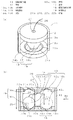
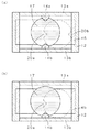
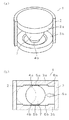
図1は、本発明の実施の形態1における衝撃検知装置11の説明図である。この衝撃検知装置11は、衝撃に弱い精密機器などに装着することにより、衝撃による機器本体の破損や誤動作等による被害を防止するものである。図1(a)は衝撃検知装置11の部分断面斜視図であり、図1(b)は衝撃検知装置11の断面図である。
(Embodiment 1)
FIG. 1 is an explanatory diagram of an impact detection device 11 according to Embodiment 1 of the present invention. The impact detection device 11 is attached to a precision device that is vulnerable to impact, thereby preventing damage to the device body due to impact or malfunction due to malfunction. FIG. 1A is a partial cross-sectional perspective view of the impact detection device 11, and FIG. 1B is a cross-sectional view of the impact detection device 11.

図1において、12は衝撃検知装置11を構成する円筒形状をした壁部であり、この壁部12の上方と下方の開口は、円板状をした支持部材13aと、支持部材13bとで夫々塞がれている。   In FIG. 1, reference numeral 12 denotes a cylindrical wall portion constituting the impact detection device 11. Upper and lower openings of the wall portion 12 are respectively formed by a disk-like support member 13 a and a support member 13 b. It is blocked.

支持部材13aの下面には略円板状の弾性部材14aが装着されるとともに、支持部材13bの上面にも略円板状の弾性部材14bが装着されている。   A substantially disk-shaped elastic member 14a is mounted on the lower surface of the support member 13a, and a substantially disk-shaped elastic member 14b is mounted on the upper surface of the support member 13b.

弾性部材14aには下方に向かって開口した凹部15aが形成されており、弾性部材14bには上方に向かって開口した凹部15bが形成されている。また、この凹部15aの外側にはドーナッツ状の溝部16aが支持部材13aに形成されており、凹部15bの外側にもドーナッツ状の溝部16bが支持部材13bに形成されている。なお、本実施の形態1において、壁部12、支持部材13a、13b、弾性部材14a、14bは共に電気的に絶縁性能を有する部材で形成されている。また、弾性部材14a、14bの摩擦係数は0.5のものを用いている。ここで、壁部12および、支持部材13a、13bには透明の部材を用いても良い。   The elastic member 14a has a concave portion 15a that opens downward, and the elastic member 14b has a concave portion 15b that opens upward. Further, a donut-shaped groove 16a is formed on the support member 13a outside the recess 15a, and a donut-shaped groove 16b is also formed on the support member 13b outside the recess 15b. In the first embodiment, the wall portion 12, the support members 13a and 13b, and the elastic members 14a and 14b are all formed of members having electrical insulation performance. The elastic members 14a and 14b have a friction coefficient of 0.5. Here, a transparent member may be used for the wall portion 12 and the support members 13a and 13b.

また、凹部15a、15b間には球体17が挟まれている。この球体17は弾性部材14a、14bの弾性力により、凹部15a、15b内に挟まれて保持されている。別の見方をすれば、球体17は弾性部材14a、14bの摩擦係数に抗して移動可能に挟まれている。   A sphere 17 is sandwiched between the recesses 15a and 15b. The spherical body 17 is sandwiched and held in the recesses 15a and 15b by the elastic force of the elastic members 14a and 14b. From another viewpoint, the sphere 17 is movably sandwiched against the friction coefficient of the elastic members 14a and 14b.

この球体17は、導電性部材で形成されており、本実施の形態1では鉄を用いている。この球体17の直径は約17mmであり、その重量は約20gのものを用いている。ここで、少なくともこの球体17の表面は導電性を有する部材で形成することが重要である。   The sphere 17 is formed of a conductive member, and iron is used in the first embodiment. The sphere 17 has a diameter of about 17 mm and a weight of about 20 g. Here, it is important that at least the surface of the sphere 17 is formed of a conductive member.

溝部16bの底面にはドーナッツ状の電極21bが敷設されている。また溝部16bの側面と底面との角部にも、夫々ドーナッツ状の電極22bが設けられている。球体17が凹部15a、15bに挟まれているときには、電極21bと電極22bとは、電気的に絶縁されており、球体17が溝部16bへ放出されたときには、電極21bと電極22bとは、球体17を介して導通する寸法関係に設計されている。   A donut-shaped electrode 21b is laid on the bottom surface of the groove 16b. Also, donut-shaped electrodes 22b are provided at the corners between the side surface and the bottom surface of the groove 16b. When the sphere 17 is sandwiched between the recesses 15a and 15b, the electrode 21b and the electrode 22b are electrically insulated, and when the sphere 17 is discharged into the groove 16b, the electrode 21b and the electrode 22b are Designed in a dimensional relationship that conducts through 17.

同様に、溝部16aの底面(図1(b)において、上側)にもドーナッツ状の電極21aが敷設されている。また溝部16aの側面と底面との角部にも、夫々ドーナッツ状の電極22aが設けられている。球体17が凹部15a、15bに挟まれているときには、電極21aと電極22aとは、電気的に絶縁されており、球体17が溝部16aへ放出されたときには、電極21aと電極22aとは、球体17を介して導通する寸法関係に設計されている。   Similarly, the donut-shaped electrode 21a is also laid on the bottom surface of the groove portion 16a (the upper side in FIG. 1B). In addition, doughnut-shaped electrodes 22a are also provided at corners between the side surface and the bottom surface of the groove 16a. When the sphere 17 is sandwiched between the recesses 15a and 15b, the electrode 21a and the electrode 22a are electrically insulated, and when the sphere 17 is discharged into the groove 16a, the electrode 21a and the electrode 22a are Designed in a dimensional relationship that conducts through 17.

なおこれは、図1に示す衝撃検知装置11の上下が逆になっている場合の説明である。
電極22bは、断面が直角三角形をしており、溝部16bの側面と底面の角に夫々形成されている。これは、球体17が溝部16bへ放出されたとき球体17と電極22b間のガタツキを防止するとともに確実に当接させるためである。同様に、電極22aも、断面が直角三角形をしており、溝部16aの側面と底面の角に夫々形成されている。これは、球体17が溝部16aへ放出されたとき球体17と電極22a間のガタツキを防止するとともに確実に当接させるためである。
This is a case where the impact detection apparatus 11 shown in FIG. 1 is upside down.
The electrode 22b has a right triangle shape in cross section, and is formed at the corners of the side surface and the bottom surface of the groove 16b. This is to prevent rattling between the sphere 17 and the electrode 22b and to ensure contact when the sphere 17 is released into the groove 16b. Similarly, the electrode 22a also has a right triangle in cross section, and is formed at the corners of the side surface and the bottom surface of the groove 16a. This is to prevent rattling between the sphere 17 and the electrode 22a when the sphere 17 is released into the groove 16a and to ensure contact.

また、凹部15a、15bの距離23は、球体17の直径24の寸法より小さく設けられており、溝部16a、16bの底面間の距離25は、球体17の直径24の寸法より大きくしている。   The distance 23 between the recesses 15a and 15b is set smaller than the dimension of the diameter 24 of the sphere 17, and the distance 25 between the bottom surfaces of the grooves 16a and 16b is set larger than the dimension of the diameter 24 of the sphere 17.

26は、球体17に装着された紐である。この紐26は、凹部15aの底面中心と、支持部材13aの中心に形成された孔27を介して外部へ導出されている。この紐26を衝撃検知装置11から外方に引くことにより、溝部16b(または16a)へ放出された球体17を再び凹部15a、15b間に保持させることができる。即ち、この紐26はリセット手段として働く。   A string 26 is attached to the sphere 17. The string 26 is led out to the outside through the center of the bottom surface of the recess 15a and the hole 27 formed in the center of the support member 13a. By pulling the string 26 outward from the impact detection device 11, the sphere 17 released to the groove 16b (or 16a) can be held between the recesses 15a and 15b again. That is, the string 26 functions as a reset means.

以上のように構成された衝撃検知装置11に強い衝撃8a(図示せず)が例えば矢印9a方向に加わったとする。なおここで、衝撃検知装置11の溝部16a、16bは上下方向が対称に形成されているため、支持部材13b側を下方にして機器に装着された場合について説明する。   It is assumed that a strong impact 8a (not shown) is applied to the impact detection device 11 configured as described above, for example, in the direction of the arrow 9a. In addition, since the groove parts 16a and 16b of the impact detection apparatus 11 are formed symmetrically in the vertical direction, a case where the support member 13b side is mounted downward and the apparatus is mounted on the device will be described.

強い衝撃8aにより、図1(b)に示すように、凹部15a、15b内に保持された球体17は、弾性部材14a、14bの弾性力に抗して溝部16bへ放出される。即ち、衝撃力を動力として働く衝撃検知手段18は、球体17と弾性部材14a、14bと及び前記凹部15a、15bから構成されている。この衝撃検知手段18は、衝撃力を動力とするので、例えば光センサや磁気センサのように電気的なエネルギーを必要としない。   Due to the strong impact 8a, as shown in FIG. 1B, the sphere 17 held in the recesses 15a and 15b is released into the groove 16b against the elastic force of the elastic members 14a and 14b. That is, the impact detection means 18 that works by using the impact force as a motive power is composed of a sphere 17, elastic members 14a and 14b, and the recesses 15a and 15b. Since the impact detection means 18 uses impact force as power, it does not require electrical energy unlike an optical sensor or a magnetic sensor, for example.

球体17が溝部16bへ放出されると、電極21bと電極22bとが球体17を介して電気的に導通される。即ち、電極21bと電極22b間の導通を検知することにより、衝撃検知装置11に強い衝撃8aが加わったことを知ることができる。このとき、球体17の直径24は、凹部15a、15bの距離23より大きいので、球体17は初期状態に戻ることはなく溝部16bに保持される。即ち、球体17と溝部16b(又は16a)とで保存手段19を形成している。この保存手段19は、重力によりその状態を保存するので、例えばRAMなどの半導体メモリのように電気的なエネルギーを必要としない。   When the sphere 17 is released into the groove 16b, the electrode 21b and the electrode 22b are electrically connected via the sphere 17. That is, by detecting the electrical connection between the electrode 21b and the electrode 22b, it can be known that a strong impact 8a has been applied to the impact detection device 11. At this time, since the diameter 24 of the sphere 17 is larger than the distance 23 between the recesses 15a and 15b, the sphere 17 is held in the groove 16b without returning to the initial state. That is, the storage means 19 is formed by the spherical body 17 and the groove portion 16b (or 16a). Since this storage means 19 stores its state by gravity, it does not require electrical energy unlike a semiconductor memory such as a RAM.

以上のように構成されているので、強い衝撃8aが発生した時点で電極21(電極21a、21bを併せた呼称、以下同じ)、電極22(電極22a、22bを併せた呼称、以下同じ)間の電気的な導通状態或いは非導通状態として検知される。従って、検知された電極21,22の信号を用いることにより衝撃検知装置11が搭載された機器に対して、即座に衝撃の発生を示す検知信号または検知状態を出力することができるために、衝撃検知装置11が搭載された機器において、危険防止、破損防止等の安全対策をしかも自動的に実施することができる。   Since it is configured as described above, when a strong impact 8a is generated, between the electrode 21 (the name including the electrodes 21a and 21b, hereinafter the same) and the electrode 22 (the name including the electrodes 22a, 22b, the same). It is detected as an electrical conduction state or non-conduction state. Accordingly, since the detected signals of the electrodes 21 and 22 can be used to immediately output a detection signal or a detection state indicating the occurrence of an impact to a device on which the impact detection device 11 is mounted. In a device equipped with the detection device 11, safety measures such as prevention of danger and prevention of damage can be automatically implemented.

また、電気的なエネルギーを用いることなく、衝撃力の検知状態を保存することができるので長期間においてエネルギーの消費を考慮することなく使用することができる。従って、この衝撃検知装置11を登載した機器は、衝撃に対して使用者が被害防止の操作を行う必要はなく、安全に使用することができる。   Moreover, since the detection state of the impact force can be stored without using electrical energy, it can be used without considering energy consumption for a long period of time. Therefore, the device on which the impact detection device 11 is mounted can be used safely without requiring the user to perform damage prevention operation against the impact.

更に、強い衝撃が有ったことを保存する保存手段19を有しているので、使用者が確認しない限り、勝手に機器の状態を元の状態に戻すことができない。従って、安全性が更に向上する。例えば、本発明の衝撃検知装置11を、精密機器であるレーザ穿刺ユニットを用いた穿刺装置に用いれば、レーザ光放射のための高電圧発生回路に設けられたコンデンサのチャージ電圧を強い衝撃の有った時点で即座に放電させることができる。従って、誤ってレーザ光が放射されることはなく、安全な穿刺装置を提供することができる。   Furthermore, since the storage means 19 for storing that there was a strong impact is provided, the state of the device cannot be restored to its original state without confirmation by the user. Therefore, safety is further improved. For example, when the impact detection device 11 of the present invention is used in a puncture device using a laser puncture unit, which is a precision instrument, the charge voltage of a capacitor provided in a high voltage generation circuit for laser light emission has a strong impact. Can be discharged immediately. Therefore, the laser beam is not accidentally emitted, and a safe puncture device can be provided.

また、紐26を用いて球体17を凹部15a、15b間に使用者の意志で戻すことができる。即ち、使用者の意志でリセットして初期状態に戻し、機器内のシステムで機器が自己判断後、正常か異常かを判断し使用者に伝え、正常な場合は、使用が継続でき、再び強い衝撃8aを検知させることができ、異常のあった場合は、サービスに連絡し、保守を行うことが可能となる。   Further, the sphere 17 can be returned between the recesses 15a and 15b by the user's will by using the string 26. In other words, reset by user's will and return to the initial state, after the device self-determined by the system in the device, determine whether it is normal or abnormal, tell the user, if normal, can continue to use and strong again The impact 8a can be detected, and if there is an abnormality, it is possible to contact the service and perform maintenance.

(実施の形態2)
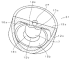
図2は、実施の形態2における衝撃検知装置31(実施の形態1における衝撃検知装置11に相当)の断面図であり、図3はその部分断面斜視図である。実施の形態2において実施の形態1と同じものについては、同符号を付して説明を簡略化している。なお、これは以降の実施の形態についても同様である。
(Embodiment 2)
2 is a cross-sectional view of an impact detection device 31 (corresponding to the impact detection device 11 in Embodiment 1) according to the second embodiment, and FIG. 3 is a partial cross-sectional perspective view thereof. In the second embodiment, the same components as those in the first embodiment are denoted by the same reference numerals, and the description is simplified. This also applies to the following embodiments.

実施の形態2では、図2に示すように、衝撃検知装置31の高さ寸法32が衝撃検知装置11における高さ寸法より小さくなっている。即ち、溝部16a、16b底面間の寸法33が球体17の直径24より若干大きい程度の寸法となっている。   In the second embodiment, as shown in FIG. 2, the height dimension 32 of the impact detection device 31 is smaller than the height dimension in the impact detection device 11. That is, the dimension 33 between the bottom surfaces of the grooves 16 a and 16 b is slightly larger than the diameter 24 of the sphere 17.

溝部16aの側面には外方に向かって傾斜した電極34が設けられている。また、同様に溝部16bの側面にも外方に向かって傾斜した電極35が設けられている。以上のような構成により、初期段階では、球体17は衝撃検知手段18を構成する弾性部材14a、14bの弾性力により、凹部15a、15bに挟まれた状態で保持されている。別の見方をすれば、球体17は弾性部材14a、14bの摩擦係数に抗して移動可能に挟まれている。この時、電極34,35間は電気的に絶縁状態である。   An electrode 34 inclined outward is provided on the side surface of the groove 16a. Similarly, an electrode 35 inclined outward is also provided on the side surface of the groove 16b. With the above configuration, at the initial stage, the sphere 17 is held in a state of being sandwiched between the recesses 15a and 15b by the elastic force of the elastic members 14a and 14b constituting the impact detection means 18. From another viewpoint, the sphere 17 is movably sandwiched against the friction coefficient of the elastic members 14a and 14b. At this time, the electrodes 34 and 35 are electrically insulated.

この状態において、例えば矢印9b方向に強い衝撃8aが加わると、球体17は点線で示すように、弾性部材14a、14bの弾性力に抗して保存手段19を構成する溝部16a、16bへ放出される。球体17が溝部16a、16bへ放出されると、この溝部16a、16bへ放出された球体17を介して、電極34,35間は電気的に導通する。この導通により、衝撃検知装置31には強い衝撃8aが加わったことを検知することができる。   In this state, for example, when a strong impact 8a is applied in the direction of the arrow 9b, the sphere 17 is released into the grooves 16a and 16b constituting the storage means 19 against the elastic force of the elastic members 14a and 14b, as indicated by the dotted lines. The When the spherical body 17 is discharged into the groove portions 16a and 16b, the electrodes 34 and 35 are electrically connected via the spherical body 17 discharged into the groove portions 16a and 16b. By this conduction, it is possible to detect that a strong impact 8a is applied to the impact detection device 31.

図3は、球体17が凹部15a、15bに挟まれた初期状態における部分断面斜視図である。本実施の形態2においては、衝撃検知装置11と比べて高さ寸法を小さくできるという特徴を有している。それ以外は、衝撃検知装置11と同様の効果を奏するものである。なお、図示していないがリセット手段についても衝撃検知装置11と同様である。   FIG. 3 is a partial cross-sectional perspective view in an initial state in which the sphere 17 is sandwiched between the recesses 15a and 15b. The second embodiment has a feature that the height dimension can be reduced as compared with the impact detection device 11. Other than that, there exists an effect similar to the impact detection apparatus 11. FIG. Although not shown, the reset means is the same as that of the impact detection device 11.

(実施の形態3)
図4は、実施の形態3における衝撃検知装置41(実施の形態1における衝撃検知装置11に相当)の断面図であり、図5はその部分断面斜視図である。実施の形態3においても実施の形態2と同様、図4に示すように、衝撃検知装置41の高さ寸法42が衝撃検知装置11における高さ寸法より小さく構成されている。即ち、溝部16a、16bの底面間の寸法43が球体17の直径24より若干大きい程度の寸法となっている。
(Embodiment 3)
FIG. 4 is a cross-sectional view of an impact detection device 41 (corresponding to the impact detection device 11 in the first embodiment) according to the third embodiment, and FIG. 5 is a partial cross-sectional perspective view thereof. Also in the third embodiment, as shown in FIG. 4, the height dimension 42 of the impact detection device 41 is configured to be smaller than the height dimension in the impact detection device 11 as in the second embodiment. That is, the dimension 43 between the bottom surfaces of the grooves 16 a and 16 b is a dimension that is slightly larger than the diameter 24 of the sphere 17.

溝部16aの底面には電極44が形成されるとともに、溝部16bの底面にも同様に電極44が形成されている。この溝部16aの底面に形成された電極44と、溝部16bの底面に形成された電極44とは導体で接続されている。また、円筒状をした壁部47(実施の形態1における壁部12に相当)の内側中央には電極45がリング状に形成されている。   An electrode 44 is formed on the bottom surface of the groove 16a, and an electrode 44 is similarly formed on the bottom surface of the groove 16b. The electrode 44 formed on the bottom surface of the groove 16a and the electrode 44 formed on the bottom surface of the groove 16b are connected by a conductor. In addition, an electrode 45 is formed in a ring shape at the inner center of the cylindrical wall portion 47 (corresponding to the wall portion 12 in the first embodiment).

以上の構成により、初期段階では、図5に示すように、球体17は衝撃検知手段18を構成する弾性部材14a、14bの弾性力により、凹部15a、15bに挟まれた状態で保持されている。別の見方をすれば、球体17は弾性部材14a、14bの摩擦係数に抗して移動可能に挟まれている。この時、電極44,45間は電気的に絶縁状態である。この状態において、例えば矢印9a方向(図4参照)に強い衝撃8aが加わったとすると、球体17は弾性部材14a、14bの弾性力に抗して、保存手段19を構成する溝部16a、16bへ放出される。球体17が溝部16a、16bへ放出されると、この溝部16a、16bへ放出された球体17を介して、電極44,45間は電気的に導通する。この導通により、衝撃検知装置41には強い衝撃8aが加わったことを検知することができる。   With the above configuration, at the initial stage, as shown in FIG. 5, the sphere 17 is held in a state sandwiched between the recesses 15 a and 15 b by the elastic force of the elastic members 14 a and 14 b constituting the impact detection means 18. . From another viewpoint, the sphere 17 is movably sandwiched against the friction coefficient of the elastic members 14a and 14b. At this time, the electrodes 44 and 45 are electrically insulated. In this state, if a strong impact 8a is applied in the direction of the arrow 9a (see FIG. 4), for example, the sphere 17 is released into the grooves 16a and 16b constituting the storage means 19 against the elastic force of the elastic members 14a and 14b. Is done. When the sphere 17 is released into the grooves 16a and 16b, the electrodes 44 and 45 are electrically connected via the sphere 17 released into the grooves 16a and 16b. By this conduction, it is possible to detect that a strong impact 8a is applied to the impact detection device 41.

図5は、球体17が凹部15a、15bに挟まれた初期状態の断面部分斜視図である。本実施の形態3においても、衝撃検知装置11と比べて高さ寸法を小さくできるという特徴を有している。また、電極44が溝部16aと溝部16bの両方の底面に形成されて互に接続されるとともに、電極45は壁部47の内側中央に設けられているので、確実に電極44と電極45とを接続させることができる。それ以外は、衝撃検知装置11と同様の効果を奏するものである。なお、図示していないがリセット手段についても衝撃検知装置11と同様である。   FIG. 5 is a partial cross-sectional perspective view of the initial state where the sphere 17 is sandwiched between the recesses 15a and 15b. The third embodiment also has a feature that the height dimension can be reduced as compared with the impact detection device 11. In addition, since the electrode 44 is formed on the bottom surfaces of both the groove 16a and the groove 16b and connected to each other, and the electrode 45 is provided at the inner center of the wall 47, the electrode 44 and the electrode 45 are securely connected. Can be connected. Other than that, there exists an effect similar to the impact detection apparatus 11. FIG. Although not shown, the reset means is the same as that of the impact detection device 11.

(実施の形態4)
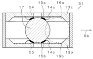
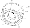
図6は、実施の形態4における衝撃検知装置51(実施の形態1における衝撃検知装置11に相当)の断面図であり、図7はその部分断面斜視図である。実施の形態4においては、電極54が凹部15aに装着されており、電極55が凹部15bに装着されている点で相違する。従って、初期状態では、電極54,55間は電気的に導通しており、強い衝撃8aが加わると、電極54,55間が電気的に絶縁されることになる。このような構成となっているので、電源(例えば電池)と負荷との間にこの衝撃検知装置51を直列に挿入しておけば、強い衝撃8aにより電源を自動的にオフすることができ、機器の安全を図ることができる。
(Embodiment 4)
6 is a cross-sectional view of an impact detection device 51 (corresponding to the impact detection device 11 in Embodiment 1) according to the fourth embodiment, and FIG. 7 is a partial cross-sectional perspective view thereof. The fourth embodiment is different in that the electrode 54 is attached to the recess 15a and the electrode 55 is attached to the recess 15b. Therefore, in the initial state, the electrodes 54 and 55 are electrically connected, and when a strong impact 8a is applied, the electrodes 54 and 55 are electrically insulated. Since it has such a configuration, if the impact detection device 51 is inserted in series between a power source (for example, a battery) and a load, the power source can be automatically turned off by a strong impact 8a. Equipment safety can be achieved.

図6は、球体17が衝撃検知手段18を構成する弾性部材14a、14bの弾性力により、凹部15a、15b間に挟まれた初期状態であり、電極54と電極55とは球体17を介して電気的に導通している。この状態において、衝撃検知装置51に強い衝撃8aが例えば矢印9b方向に加わると、球体17は点線で示したように、弾性部材14a、14bの弾性力に抗して保存手段19を構成する溝部16a、16bへ放出される。そうすると、電極54と電極55とは電気的に絶縁されてオフ状態となる。この電極54と電極55間の非導通により、衝撃検知装置51には強い衝撃8aが加わったことを検知することができる。   FIG. 6 shows an initial state where the sphere 17 is sandwiched between the recesses 15 a and 15 b by the elastic force of the elastic members 14 a and 14 b constituting the impact detection means 18, and the electrode 54 and the electrode 55 are interposed via the sphere 17. Electrically conducting. In this state, when a strong impact 8a is applied to the impact detection device 51, for example, in the direction of the arrow 9b, the sphere 17 forms a groove portion that constitutes the storage means 19 against the elastic force of the elastic members 14a and 14b, as indicated by the dotted line Released to 16a and 16b. Then, the electrode 54 and the electrode 55 are electrically insulated and are turned off. Due to the non-conduction between the electrode 54 and the electrode 55, it is possible to detect that a strong impact 8a is applied to the impact detection device 51.

図7は、球体17が衝撃検知手段18を構成する弾性部材14a、14bの弾性力により、凹部15a、15b間に挟まれた初期状態の部分断面斜視図である。本実施の形態4は、強い衝撃8aにより電極54と電極55間を電気的にオフするという特徴を有している。それ以外は、衝撃検知装置31と同様の効果を奏するものである。なお、図示していないがリセット手段については、衝撃検知装置11と同様である。   FIG. 7 is a partial cross-sectional perspective view of the initial state where the sphere 17 is sandwiched between the recesses 15 a and 15 b by the elastic force of the elastic members 14 a and 14 b constituting the impact detection means 18. The fourth embodiment has a feature that the electrode 54 and the electrode 55 are electrically turned off by a strong impact 8a. Other than that, there exists an effect similar to the impact detection apparatus 31. FIG. Although not shown, the reset means is the same as that of the impact detection device 11.

(実施の形態5)
図8(a)は、球体17が弾性体の凸部14a、14b間に挟まれた初期状態の断面図である。本実施の形態5は、球体の一部に凹み部20aならびに20bを有し、支持体13aならびに13bに凸部を設け、さらに支持体の凸部を弾性体で構成したという特徴を有している。それ以外は、衝撃検知装置31と同様の効果を奏するものである。なお、図示していないがリセット手段については、衝撃検知装置11と同様である。なお、弾性体の凸部14a,14bは、弾性体の硬さを選択することや、大きさを調整することで、図8(b)に示すように、支持体の片方に形成することでも、同様の効果を得ることが出来る。上記のように、衝撃検知手段18及び保存手段19は、凹み部20aならびに20bを有する球体17と弾性体の凸部14a、14bから構成されており、且つ一体化されており、前記凹み部20aならび20bを有する球体17と弾性体の凸部14a、14bとの係合関係により衝撃力検知状態及び保存状態を維持することになる。
(Embodiment 5)
FIG. 8A is a cross-sectional view of the initial state in which the sphere 17 is sandwiched between the convex portions 14a and 14b of the elastic body. The fifth embodiment has the feature that the spheres have the recessed portions 20a and 20b, the convex portions are provided on the support bodies 13a and 13b, and the convex portions of the support body are made of an elastic body. Yes. Other than that, there exists an effect similar to the impact detection apparatus 31. FIG. Although not shown, the reset means is the same as that of the impact detection device 11. The convex portions 14a and 14b of the elastic body may be formed on one side of the support body as shown in FIG. 8B by selecting the hardness of the elastic body or adjusting the size. A similar effect can be obtained. As described above, the impact detection means 18 and the storage means 19 are composed of the spherical body 17 having the recessed portions 20a and 20b and the convex portions 14a and 14b of the elastic body, and are integrated, and the recessed portion 20a. The impact force detection state and the storage state are maintained by the engagement relationship between the spherical body 17 having the line 20b and the convex portions 14a and 14b of the elastic body.

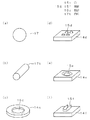
図9の(a)、(b)には、衝撃検知手段18を構成する要素である可動部分(上述の実施の形態1〜4における球体17に相当)の例を示している。衝撃検知手段18は、衝撃力を動力とし、挟持された状態から、離脱できる形状であればよく、図9(a)に示す概略球体形状の球体17の他に、図9(b)に示す円柱17bなどでも構成が可能である。   9A and 9B show an example of a movable part (corresponding to the sphere 17 in the above-described first to fourth embodiments) that is an element constituting the impact detection means 18. The impact detection means 18 only needs to have a shape that can be detached from the clamped state using the impact force as power. In addition to the roughly spherical sphere 17 shown in FIG. 9A, the impact detection means 18 is shown in FIG. 9B. The configuration can be made with a cylinder 17b or the like.

また、図9(c)(d)(e)(f)に示すのは、衝撃検知手段18を構成する固定部分(上述の実施の形態1〜4における弾性体14a、14b及び凹部15a、15bに相当)である支持体上に形成する弾性体の形状である。弾性体は、衝撃検知手段が、所定の以下の衝撃力を得たときに、保持する保持力を持てばよく、図9(c)に示すように、円板状のシート14cに概略輪のような形状の穴15cを設けることで形成したり、図示しないが、楕円状に形成したり、円板でなく、矩形のシートに形成することも可能である。さらに、図9(d)に示すように、凸部15dを複数個設け、複数点で、衝撃検知手段と接触するように構成することも可能である。さらに、図9(e)に示すように、平板や円板状のシート14eに凹み部15eを持たせることでも構成が可能である。さらに、図9(f)に示すように、衝撃検知手段が円筒型の場合は、円筒側面に即した形の支持部をベース14f及び突起15fから構成することも可能である。   9 (c), (d), (e), and (f) show a fixed portion constituting the impact detection means 18 (the elastic bodies 14a and 14b and the recesses 15a and 15b in the first to fourth embodiments described above). The shape of the elastic body formed on the support. The elastic body only needs to have a holding force to be held when the impact detection means obtains an impact force equal to or less than a predetermined value. As shown in FIG. It can be formed by providing the hole 15c having such a shape, or although not shown, it can be formed in an elliptical shape or a rectangular sheet instead of a disk. Further, as shown in FIG. 9 (d), it is possible to provide a plurality of convex portions 15d and to make contact with the impact detection means at a plurality of points. Furthermore, as shown in FIG. 9 (e), the flat plate or the disk-shaped sheet 14e can also be configured by having a recess 15e. Furthermore, as shown in FIG. 9 (f), when the impact detection means is a cylindrical type, it is possible to form a support portion conforming to the cylindrical side surface from the base 14f and the protrusion 15f.

なお、支持部材上の弾性体は、復元力を有する弾性部材であればよく、例えば、二トリルゴムや、シリコーンゴム、ブチルゴム、フッ素ゴム、ウレタンゴム、から選択可能であり、その硬さは、形状によって、異なるが、JIS K 6301 の場合の表記で20Hsから90Hsの範囲で選択されることが望ましい。   The elastic body on the support member may be an elastic member having a restoring force, and can be selected from, for example, nitrile rubber, silicone rubber, butyl rubber, fluorine rubber, and urethane rubber, and the hardness thereof is a shape. However, it is desirable to select in the range of 20Hs to 90Hs in the notation of JIS K6301.

(実施の形態6)
図10は、実施の形態6における穿刺装置61の断面図である。穿刺装置61は、レーザ穿刺ユニット62を用いて患者の皮膚63(図11参照)を穿刺し、この穿刺した皮膚63から血液65(図11参照)を滲出させるためのものである。この滲出した血液65を点着させた血液センサを、別途血液測定装置に装着して、血糖値やコレステロール等血液65の性質を測定することができる。
(Embodiment 6)
FIG. 10 is a cross-sectional view of puncture apparatus 61 in the sixth embodiment. The puncture device 61 punctures a patient's skin 63 (see FIG. 11) using a laser puncture unit 62, and exudes blood 65 (see FIG. 11) from the punctured skin 63. A blood sensor on which the exuded blood 65 is spotted can be separately attached to a blood measuring device, and the properties of the blood 65 such as blood glucose level and cholesterol can be measured.

本実施の形態6における穿刺装置61は、前述の衝撃検知装置を搭載している。図10において、66は穿刺装置61の筐体であり、この筐体66の一方には筒体66aが形成されている。そして、この筒体66aの先端には、穿刺部67が設けられている。この穿刺部67は患者の皮膚63が当接されるものである。また、この穿刺部67に対向してレーザ穿刺ユニット62が装着されている。レーザ穿刺ユニット62には、励起用のフラッシュランプ62bとレーザロッド62cが並行に装着されている。このレーザロッド62cの前方にはレンズ62fが装着されており、レーザロッド62cから放射されたレーザ光62eは、レンズ62fにより皮膚63の表面近傍で焦点を結ぶように配置されている。   The puncture device 61 in the sixth embodiment is equipped with the aforementioned impact detection device. In FIG. 10, reference numeral 66 denotes a casing of the puncture device 61, and a cylindrical body 66 a is formed on one side of the casing 66. And the puncture part 67 is provided in the front-end | tip of this cylinder 66a. The puncture portion 67 is a portion against which the patient's skin 63 comes into contact. A laser puncture unit 62 is attached to face the puncture portion 67. The laser puncture unit 62 is equipped with an excitation flash lamp 62b and a laser rod 62c in parallel. A lens 62f is mounted in front of the laser rod 62c, and the laser light 62e emitted from the laser rod 62c is disposed so as to be focused near the surface of the skin 63 by the lens 62f.

レーザ穿刺ユニット62の後方には電池68が着脱自在に挿入されている。また、レーザ穿刺ユニット62と並んで高電圧発生回路69と負圧手段70が設けられている。高電圧発生回路69は、レーザ穿刺ユニット62からレーザ光62eを放射させるための高電圧を発生させるための回路である。また、負圧手段70は、負圧路70aを介して筒体66a内と穿刺部67を負圧にするものである。   A battery 68 is detachably inserted behind the laser puncture unit 62. In addition to the laser puncture unit 62, a high voltage generation circuit 69 and a negative pressure means 70 are provided. The high voltage generation circuit 69 is a circuit for generating a high voltage for emitting the laser light 62e from the laser puncture unit 62. Moreover, the negative pressure means 70 makes the inside of the cylinder 66a and the puncture part 67 a negative pressure via the negative pressure path 70a.

11は、前述の実施の形態1で説明した衝撃検知装置であり、電池68の下方(図10において)に配置されている。この衝撃検知装置11を構成する壁部12は、壁部12の円筒形状の方向とフラッシュランプ62bの長手方向とが平行に配置されるように装着することが重要である。その理由は、フラッシュランプ62bは長手方向と直角に加わる衝撃に弱いので、衝撃検知装置11を構成する壁部12の円筒形状の方向と、フラッシュランプ62bの長手方向とを同方向にして、フラッシュランプ62bの構成上最も衝撃による影響が大きい方向に対する衝撃検知感度を向上させるためである。なお、衝撃検知装置11に対して直角の方向になるように、他の衝撃検知装置11aを配置すると2次元の方向からの衝撃を検知することができ、更に検知精度は向上し安全性を図ることが出来る。   Reference numeral 11 denotes the impact detection device described in the first embodiment, which is disposed below the battery 68 (in FIG. 10). It is important that the wall portion 12 constituting the impact detection device 11 is mounted such that the cylindrical direction of the wall portion 12 and the longitudinal direction of the flash lamp 62b are arranged in parallel. The reason is that the flash lamp 62b is vulnerable to an impact applied at right angles to the longitudinal direction, so that the cylindrical direction of the wall portion 12 constituting the impact detection device 11 and the longitudinal direction of the flash lamp 62b are set in the same direction. This is to improve the impact detection sensitivity in the direction in which the influence of the impact is the largest on the configuration of the lamp 62b. If another impact detection device 11a is arranged so as to be in a direction perpendicular to the impact detection device 11, an impact from a two-dimensional direction can be detected, and detection accuracy is further improved and safety is improved. I can do it.

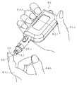
以上のように構成された穿刺装置61を、例えば図11に示すように右手64aで握り、穿刺部67を左手64bの人差し指64cの皮膚63に当接させる。そして、右手64aの薬指64dで穿刺ボタン62aを押下する。そうすると、穿刺装置61からはレーザ光62eが放射され、皮膚63を穿刺する。皮膚63が穿刺されると皮膚63からは血液65が滲出する。   For example, as shown in FIG. 11, the puncture device 61 configured as described above is gripped by the right hand 64a, and the puncture portion 67 is brought into contact with the skin 63 of the index finger 64c of the left hand 64b. Then, the puncture button 62a is pressed with the ring finger 64d of the right hand 64a. Then, the puncture device 61 emits laser light 62e and punctures the skin 63. When the skin 63 is punctured, blood 65 exudes from the skin 63.

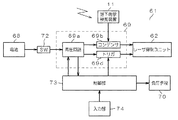
図12は、穿刺装置61の電気回路及びその周辺部分のブロック図である。図12において、電池68は電源スイッチ72を介して昇圧回路69aに接続されている。この昇圧回路69aは制御部73に接続されている。また、昇圧回路69aの出力はコンデンサ69bに接続され、このコンデンサ69bに高電圧がチャージされる。このコンデンサ69bの出力はレーザ穿刺ユニット62に接続されている。更に、昇圧回路69aの出力はトリガ回路69dを介してレーザ穿刺ユニット62に接続されている。昇圧回路69aとコンデンサ69bとトリガ回路69dとにより高電圧発生回路69が構成されている。   FIG. 12 is a block diagram of an electric circuit of puncture device 61 and its peripheral portion. In FIG. 12, a battery 68 is connected to a booster circuit 69a via a power switch 72. The booster circuit 69 a is connected to the control unit 73. The output of the booster circuit 69a is connected to a capacitor 69b, and the capacitor 69b is charged with a high voltage. The output of the capacitor 69b is connected to the laser puncture unit 62. Further, the output of the booster circuit 69a is connected to the laser puncture unit 62 via the trigger circuit 69d. A booster circuit 69a, a capacitor 69b, and a trigger circuit 69d constitute a high voltage generation circuit 69.

制御部73には穿刺ボタン62a等で構成された入力部74が接続されている。また、制御部73は、負圧手段70にも接続されている。また、衝撃検知装置11の電極21,22は低抵抗69e(図17参照)を介してコンデンサ69bの両端に接続されている。   An input unit 74 composed of a puncture button 62a and the like is connected to the control unit 73. The control unit 73 is also connected to the negative pressure means 70. Further, the electrodes 21 and 22 of the impact detection device 11 are connected to both ends of the capacitor 69b through a low resistance 69e (see FIG. 17).

ここで、衝撃検知装置11は、高電圧発生回路69を構成するコンデンサ69bに接続されており、衝撃検知装置11において、外部からの衝撃を検知した場合は、安全のため、コンデンサ69bにチャージされている高電圧の電荷を放電させる。   Here, the impact detection device 11 is connected to a capacitor 69b constituting the high voltage generation circuit 69, and when the impact detection device 11 detects an external impact, the capacitor 69b is charged for safety. Discharge high voltage charge.

さらに、前記電源スイッチ72と接続しておき、衝撃を検知した場合には速やかに電源スイッチを切るようにする電源断連動機能も搭載可能である。このように、衝撃検知装置11を内蔵することで、非常時における安全対策が可能となる。   Further, it is possible to mount a power-off interlock function that is connected to the power switch 72 and quickly turns off the power switch when an impact is detected. Thus, by incorporating the impact detection device 11, safety measures in an emergency can be realized.

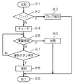
図13は、前記衝撃検知装置11を搭載した穿刺装置61(図12参照)の動作を示すフローチャートである。先ず、ステップ81において、電源スイッチ72をオンする。次に、ステップ82へ移行する。ステップ82では、衝撃検知装置11を構成する球体17が溝部16a(又は16b、図1など参照))に有るか否かを電極21,22(図1など参照)の導通により確かめる。なお、壁部12を透明部材で形成しておけば球体17の状態を目視で確かめることもできる。   FIG. 13 is a flowchart showing the operation of the puncture device 61 (see FIG. 12) on which the impact detection device 11 is mounted. First, in step 81, the power switch 72 is turned on. Next, the process proceeds to step 82. In step 82, whether or not the sphere 17 constituting the impact detection device 11 is in the groove 16a (or 16b, see FIG. 1, etc.) is confirmed by the conduction of the electrodes 21, 22 (see FIG. 1, etc.). In addition, if the wall part 12 is formed with a transparent member, the state of the spherical body 17 can also be confirmed visually.

電極21,22間が導通していれば、衝撃検知装置11に外部からの強い衝撃8aが加わったままの状態であり、穿刺装置61は使用不能の状態、即ちロックされた状態になっているわけである。このロック状態の場合は、ステップ83へ移行し、穿刺装置61に異常がないことを確かめた後、紐26(図1参照)を引いて(リセット手段を用いてリセットする)球体17を凹部15a、15b間に載置し(ロック解除し)、衝撃検知装置11を初期状態にした後、動作を終了する。   If the electrodes 21 and 22 are conductive, the impact detection device 11 is still subjected to a strong impact 8a from the outside, and the puncture device 61 is unusable, that is, locked. That is why. In this locked state, the process proceeds to step 83, and after confirming that there is no abnormality in the puncture device 61, the string 17 (see FIG. 1) is pulled (reset using the reset means) and the sphere 17 is recessed 15a. , 15b (unlocked), the impact detection device 11 is initialized, and the operation ends.

ステップ82において、電極21,22間が導通していなければ、先にリセットした時点以降、衝撃検知装置11に強い衝撃8aが加わっていない状態であり、穿刺装置61はアンロックの状態になっている。この場合は、ステップ84へ移行する。   In step 82, if the electrodes 21 and 22 are not conducting, the strong impact 8a has not been applied to the impact detection device 11 since the time of the reset, and the puncture device 61 is in the unlocked state. Yes. In this case, the process proceeds to step 84.

ステップ84では電池68から供給される電圧を高電圧発生回路69内の昇圧回路69aで昇圧する。この昇圧された電圧はコンデンサ69bにチャージされるとともにレーザ穿刺ユニット62に加えられる。コンデンサ69bにチャージされた電圧が予め定められた穿刺電圧(300V以上)になったら、ステップ85へ移行する。   In step 84, the voltage supplied from the battery 68 is boosted by the booster circuit 69a in the high voltage generation circuit 69. This boosted voltage is charged to the capacitor 69b and applied to the laser puncture unit 62. When the voltage charged in the capacitor 69b becomes a predetermined puncture voltage (300 V or more), the routine proceeds to step 85.

ステップ85では、コンデンサ69bには高電圧がチャージされた状態であり、この状態においても、衝撃検知装置11に強い衝撃が加わったか否かを常に検知している。この状態が続く、その間に若し強い衝撃8aが加われば、レーザ穿刺ユニット62が故障する可能性があり、この故障による危険を回避するためにステップ86へ移行する。ステップ86でコンデンサ69bにチャージされた高電圧の電荷を放電する。即ち、コンデンサ69bにチャージされた高電圧を電極21と球体17と電極22とで短絡させて放電させる。放電させて安全になった後、終了する。   In step 85, the capacitor 69b is in a state of being charged with a high voltage. Even in this state, it is always detected whether or not a strong impact has been applied to the impact detection device 11. If this state continues and if a strong impact 8a is applied during that time, the laser puncture unit 62 may break down, and the routine proceeds to step 86 in order to avoid danger due to this failure. In step 86, the high voltage charge charged in the capacitor 69b is discharged. That is, the high voltage charged in the capacitor 69b is short-circuited by the electrode 21, the sphere 17 and the electrode 22 to be discharged. Finish after discharging to be safe.

ステップ85において、衝撃検知装置11に強い衝撃が加わらなかった場合には、ステップ87へ移行し、入力部74(図12参照)に設けられた穿刺ボタン62aが押下されたか否をチェックする。穿刺ボタン62aが押下されていなければステップ85へ戻り、衝撃8aが有るか無いかを衝撃検知装置11により、都度チェックしている。ここで、穿刺ボタン62aが押下されると、ステップ88へ移行し、コンデンサ69bにチャージされたエネルギーは、レーザ穿刺ユニット62内のフラッシュランプ62bに供給され、フラッシュランプ62bから励起光がレーザロッド62cに放射され、その後レーザロッド62c内でエネルギーが増幅され、レーザ光62eが発射されて患者の皮膚63を穿刺する。即ち、穿刺ボタン62aの押下が検知されると、高電圧発生回路69内のトリガ回路69dが働き、レーザ穿刺ユニット62からはレーザ光62eが放射される。ステップ88において、穿刺が終了するとステップ89へ移行し一連の動作は終了する。   In step 85, when a strong impact is not applied to the impact detection device 11, the process proceeds to step 87, and it is checked whether or not the puncture button 62a provided on the input unit 74 (see FIG. 12) has been pressed. If the puncture button 62a has not been pressed, the process returns to step 85, and the impact detection device 11 checks whether or not there is an impact 8a. Here, when the puncture button 62a is pressed, the routine proceeds to step 88 where the energy charged in the capacitor 69b is supplied to the flash lamp 62b in the laser puncture unit 62, and excitation light is emitted from the flash lamp 62b to the laser rod 62c. After that, energy is amplified in the laser rod 62c, and a laser beam 62e is emitted to puncture the skin 63 of the patient. That is, when pressing of the puncture button 62 a is detected, the trigger circuit 69 d in the high voltage generation circuit 69 operates and the laser puncture unit 62 emits laser light 62 e. In step 88, when the puncture is completed, the process proceeds to step 89, and the series of operations is completed.

以上説明したように、レーザ穿刺ユニット62を用いた穿刺装置61に本発明の衝撃検知装置11を用いているので、強い衝撃8aが加わった場合には、衝撃検知装置11により検知され、穿刺装置61は動作禁止の状態のままで保持されるようになっており、間違って使用されることはなく安全である。即ち、強い衝撃8aを受けた時点で、コンデンサ69bにチャージされた高電圧は自動的に放電される。また、ステップ82におけるロック状態は、球体17が溝部16b(または16a)に保持された状態であり、勝手に復帰することはなくその状態を保持している。従って、使用者が安全を確認した上で初期状態に戻す(リセットする)ことになり安全は確保される。   As described above, since the impact detection device 11 of the present invention is used in the puncture device 61 using the laser puncture unit 62, when the strong impact 8a is applied, the impact detection device 11 detects the impact and the puncture device. 61 is held in an operation-inhibited state and is safe from being used by mistake. That is, when the strong impact 8a is received, the high voltage charged in the capacitor 69b is automatically discharged. Further, the locked state in step 82 is a state in which the sphere 17 is held in the groove 16b (or 16a), and the state is maintained without returning without permission. Therefore, after the user confirms safety, the user returns to the initial state (reset), and safety is ensured.

なお、本実施の形態6では、衝撃検知装置11を用いたが、これは衝撃検知装置31、41を用いても良い。また、衝撃検知装置51を電源スイッチ72と直列に用いても良い。   In the sixth embodiment, the impact detection device 11 is used. However, the impact detection devices 31 and 41 may be used. Further, the impact detection device 51 may be used in series with the power switch 72.

(実施の形態7)
図14は、実施の形態7における血液検査装置101の断面図である。血液検査装置101は、皮膚に穿刺して血液65を採取する穿刺装置と血液65の性質を測定する測定装置とが一体化されたものであり、本発明である前述の衝撃検知装置11を搭載している。
図14において、102は血液検査装置101の筐体であり、この筐体102の一方には筒体102aが形成されている。そして、この筒体102a先端の開口部には着脱自在のホルダ103が装着されて穿刺部104を形成している。また、このホルダ103と筒体102aとの間には、血液センサ105が着脱自在に装着されている。この血液センサ105から出力される信号は、コネクタ133を介して電気回路部106(高電圧発生回路69と測定回路107が含まれている)に接続されている。
(Embodiment 7)
FIG. 14 is a cross-sectional view of blood test apparatus 101 in the seventh embodiment. The blood test apparatus 101 is a combination of a puncture apparatus that punctures the skin and collects blood 65 and a measurement apparatus that measures the properties of blood 65, and is equipped with the above-described impact detection apparatus 11 according to the present invention. is doing.
In FIG. 14, reference numeral 102 denotes a housing of the blood test apparatus 101, and a cylindrical body 102 a is formed on one side of the housing 102. A detachable holder 103 is attached to the opening at the tip of the cylindrical body 102a to form a puncture portion 104. A blood sensor 105 is detachably mounted between the holder 103 and the cylinder 102a. A signal output from the blood sensor 105 is connected to an electric circuit unit 106 (including a high voltage generation circuit 69 and a measurement circuit 107) via a connector 133.

また、電池68の下方に、実施の形態6と同様、衝撃検知装置11が装着されている。また、この衝撃検知装置11の方向と直角の方向に他の衝撃検知装置11aを装着すると衝撃の方向を2次元的に検知することができ、更に衝撃に対する検知性能を向上させることができる。   Further, the impact detection device 11 is mounted below the battery 68 as in the sixth embodiment. Further, if another impact detection device 11a is mounted in a direction perpendicular to the direction of the impact detection device 11, the direction of the impact can be detected two-dimensionally, and the detection performance against the impact can be further improved.

図15は、ホルダ103(図14参照)に装着される血液センサ105の断面図である。血液検査装置101に使用される血液センサ105は、基板111と、スペーサ112と、カバー113とで構成されている。   FIG. 15 is a cross-sectional view of blood sensor 105 attached to holder 103 (see FIG. 14). The blood sensor 105 used in the blood test apparatus 101 includes a substrate 111, a spacer 112, and a cover 113.

114は、血液センサ105の略中央を貫通して設けられた血液65(図11参照)の貯留部である。   Reference numeral 114 denotes a storage portion for blood 65 (see FIG. 11) provided so as to penetrate substantially the center of the blood sensor 105.

115は、この貯留部114に一方の端が連結された血液65の供給路であり、貯留部114に溜められた血液65を毛細管現象により律速で検出部117へ導くための通路である。また、この供給路115の他の端は空気孔118へ連通されている。   Reference numeral 115 denotes a supply path for blood 65 having one end connected to the storage section 114, and is a path for guiding blood 65 stored in the storage section 114 to the detection section 117 at a rate-determining rate by capillary action. Further, the other end of the supply path 115 communicates with the air hole 118.

130は、検出部117上に載置された試薬である。この試薬130は、0.01〜2.0wt%CMC水溶液に、PQQ−GDHを0.1〜5.0U/センサ、フェリシアン化カリウムを10〜200mM、マルチトールを1〜50mM、タウリンを20〜200mM添加して融解させて試薬溶液を調整し、これを基板111に形成された検出部117を構成する検出電極121,123(図16参照)上に滴下し、乾燥させることで形成したものである。   130 is a reagent placed on the detection unit 117. This reagent 130 is 0.01 to 2.0 wt% CMC aqueous solution, PQQ-GDH 0.1 to 5.0 U / sensor, potassium ferricyanide 10 to 200 mM, maltitol 1 to 50 mM, and taurine 20 to 200 mM. The reagent solution is prepared by adding and melting the solution, and the reagent solution is dropped on the detection electrodes 121 and 123 (see FIG. 16) constituting the detection unit 117 formed on the substrate 111 and dried. .

基板111の上面には金、白金、パラジウム等を材料として、スパッタリング法或いは蒸着法により導電層を形成し、これをレーザ加工により検出電極121〜125(図16参照)と、この検出電極121〜125から夫々導出された接続電極121a〜126aが一体的に形成されている。   On the upper surface of the substrate 111, a conductive layer is formed by sputtering or vapor deposition using gold, platinum, palladium or the like as a material, and this is subjected to laser processing to detect electrodes 121 to 125 (see FIG. 16) and the detect electrodes 121 to Connection electrodes 121 a to 126 a respectively led out from 125 are integrally formed.

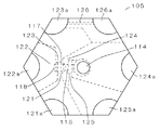
図16は、血液センサ105の透視平面図であり、この血液センサ105の外周上には、接続電極121a〜126aが形成されている。接続電極123aと接続電極126aとの間に、導電体パターンで形成された識別部126が形成されている。   FIG. 16 is a perspective plan view of blood sensor 105, and connection electrodes 121 a to 126 a are formed on the outer periphery of blood sensor 105. An identification part 126 formed of a conductor pattern is formed between the connection electrode 123a and the connection electrode 126a.

供給路115上には、貯留部114側から順に接続電極125aに接続された検出電極125と、接続電極124aに接続された検出電極124と、接続電極123aに接続された検出電極123と、接続電極121aに接続された検出電極121と、接続電極122aに接続された検出電極122が設けられている。また、検出電極121,123上には、試薬130(図15参照)が載置される。血液センサ105は略円形(正6角形)であり、各接続電極121a〜126aの特定は、隣り合う電極間に導通があるか無いかに基づいて各接続電極121a〜126aを夫々特定している。   On the supply path 115, a detection electrode 125 connected to the connection electrode 125 a in order from the storage portion 114 side, a detection electrode 124 connected to the connection electrode 124 a, a detection electrode 123 connected to the connection electrode 123 a, and a connection A detection electrode 121 connected to the electrode 121a and a detection electrode 122 connected to the connection electrode 122a are provided. A reagent 130 (see FIG. 15) is placed on the detection electrodes 121 and 123. Blood sensor 105 is substantially circular (regular hexagon), and each connection electrode 121a to 126a is specified based on whether or not there is conduction between adjacent electrodes.

即ち、隣り合う電極間の電気的な導通があるか無いかで、接続電極123a、126aが特定される。この接続電極123a、126aを基準にして他の接続電極124a、125a、121a、122aが特定される。また、接続電極123a、126a間の導通を用いて、血液センサ105がホルダ103に装着されたか否かを識別することができる。   That is, the connection electrodes 123a and 126a are specified depending on whether or not there is electrical conduction between adjacent electrodes. The other connection electrodes 124a, 125a, 121a, 122a are specified based on the connection electrodes 123a, 126a. Further, it is possible to identify whether or not the blood sensor 105 is attached to the holder 103 by using conduction between the connection electrodes 123a and 126a.

また、識別部126の電気抵抗値を変えることにより、使用する検量線の情報を格納したり、製造情報を格納したりすることが可能となる。従って、これらの情報を用いて、より精密な血液検査を行なうことができる。   Further, by changing the electric resistance value of the identification unit 126, it is possible to store information on the calibration curve to be used or store manufacturing information. Therefore, a more precise blood test can be performed using these pieces of information.

次に血液センサ105を使って、血液の測定を行なう血液検査装置101(図14参照)の動作について説明する。血系検査装置101の筒体102aの先端部である穿刺部104に指を当接する。指が当接されると、皮膚検知または釦により負圧手段70が起動し、穿刺部などが負圧され、指の皮膚が盛上る。   Next, the operation of blood test apparatus 101 (see FIG. 14) that measures blood using blood sensor 105 will be described. A finger is brought into contact with the puncture unit 104 which is the tip of the cylindrical body 102a of the blood system testing apparatus 101. When the finger comes into contact, the negative pressure means 70 is activated by skin detection or a button, the puncture part or the like is negatively pressurized, and the skin of the finger rises.

血液検査装置101に搭載されているレーザ穿刺ユニット62から発射されたレーザ光によりその盛上った皮膚が穿刺され、皮膚から血液65が滲出する。血液センサ105の貯留部114に前記血液65が流入すると、この血液65は供給路115内を毛細管現象で、検出電極125,123を順に通過して検出電極122上へ導入される。血液65が血液センサ105の検出電極122へ導かれることにより、検出電極122より手前にある検出部117を構成する検出電極121,123へ十分な血液65が到達していること知ることができる。   The raised skin is punctured by the laser light emitted from the laser puncture unit 62 mounted on blood test apparatus 101, and blood 65 exudes from the skin. When the blood 65 flows into the storage part 114 of the blood sensor 105, the blood 65 is introduced into the detection electrode 122 through the detection electrodes 125 and 123 in order by capillary action in the supply path 115. By introducing the blood 65 to the detection electrode 122 of the blood sensor 105, it can be known that sufficient blood 65 has reached the detection electrodes 121 and 123 constituting the detection unit 117 in front of the detection electrode 122.

この血液65は、血液センサ105の試薬130と電気化学的な酸化還元反応を起こす。その反応結果である微細な電流は接続電極121a、123aに導かれ、コネクタ133を経由して血液検査内の測定回路107(電気回路部106内に搭載)に接続され、測定・検査される。なお、血液65が検出電極122へ到達したタイミングで、負圧手段70をオフすると良い。   The blood 65 causes an electrochemical redox reaction with the reagent 130 of the blood sensor 105. A fine current as a result of the reaction is guided to the connection electrodes 121a and 123a, connected to the measurement circuit 107 in the blood test (mounted in the electric circuit unit 106) via the connector 133, and measured and tested. The negative pressure means 70 may be turned off at the timing when the blood 65 reaches the detection electrode 122.

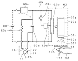
図17は、レーザ穿刺ユニット62と、このレーザ穿刺ユニット62に高電圧を供給する高電圧発生回路69及び衝撃検知装置11のブロック図である。高電圧発生回路69は、電池68に接続された昇圧回路69aと、この昇圧回路69aの出力に接続されたコンデンサ69bと、このコンデンサ69bに接続されたトリガスイッチ69cと、このトリガスイッチ69cの出力に接続されたトリガ回路69dとで構成されている。コンデンサ69bは形状が大型となるため、レーザ穿刺ユニット62の近傍に単独配置されることもある。また、コンデンサ69bの両端は、レーザ穿刺ユニット62を構成するフラッシュランプ62bの両電極に接続されており、トリガ回路69dの出力はフラッシュランプ62bのトリガ電極に接続されている。   FIG. 17 is a block diagram of the laser puncture unit 62, the high voltage generation circuit 69 that supplies a high voltage to the laser puncture unit 62, and the impact detection device 11. The high voltage generation circuit 69 includes a booster circuit 69a connected to the battery 68, a capacitor 69b connected to the output of the booster circuit 69a, a trigger switch 69c connected to the capacitor 69b, and an output of the trigger switch 69c. And a trigger circuit 69d connected to the. Since the capacitor 69b has a large shape, it may be arranged alone in the vicinity of the laser puncture unit 62. Both ends of the capacitor 69b are connected to both electrodes of the flash lamp 62b constituting the laser puncture unit 62, and the output of the trigger circuit 69d is connected to the trigger electrode of the flash lamp 62b.

また、コンデンサ69bの一方は、低抵抗69eを介して衝撃検知装置11の電極21に接続されている。コンデンサ69bの他方は、直接電極22に接続されている。なお、低抵抗69eはコンデンサ69bの他方側と電極22間に挿入しても良い。
コンデンサ69bは、静電容量450μF(マイクロファラッド)で耐圧350Vのものを用い、トリガスイッチ69cにはIGBT(絶縁ゲートバイポーラトランジスタ)を用いている。このトリガスイッチ69cは、図19で示す穿刺ボタン62aの出力でオン・オフが制御される。
One of the capacitors 69b is connected to the electrode 21 of the impact detection device 11 through a low resistance 69e. The other side of the capacitor 69 b is directly connected to the electrode 22. The low resistance 69e may be inserted between the other side of the capacitor 69b and the electrode 22.
The capacitor 69b has a capacitance of 450 μF (microfarad) and a withstand voltage of 350V, and the trigger switch 69c uses an IGBT (insulated gate bipolar transistor). The trigger switch 69c is controlled to be turned on / off by the output of the puncture button 62a shown in FIG.

レーザ穿刺ユニット62は、フラッシュランプ62bと、このフラッシュランプ62bの近傍に設けられるとともにEr:YAG(イットリウム・アルミニウム・ガーネット)で形成されたレーザロッド62cと、このレーザロッド62cの前方に設けられたレンズ62fとで構成されている。また、レーザロッド62cの後方には全反射鏡62gが装着されるとともに前方には部分透過鏡62hが装着されている。   The laser puncture unit 62 is provided with a flash lamp 62b, a laser rod 62c provided in the vicinity of the flash lamp 62b and formed of Er: YAG (yttrium, aluminum, garnet), and a front of the laser rod 62c. It is composed of a lens 62f. A total reflection mirror 62g is attached to the rear of the laser rod 62c, and a partial transmission mirror 62h is attached to the front.

次に、レーザ穿刺ユニット62の動作を説明する。電池68から供給された電圧は、昇圧回路69aで昇圧されてコンデンサ69bを充電する。この充電電圧は外部から昇圧回路69aの制御が可能であり、この充電電圧の制御で穿刺深さに対応したレーザ光の出力レベルを制御することができる。コンデンサ69bに充電された電圧はフラッシュランプ62bの両電極に供給される。この電圧が予め定められた電圧(300V以上)まで昇圧された後、穿刺ボタン62aを押下する。すると、トリガ回路69dが働き、フラッシュランプ62bが発光する。   Next, the operation of the laser puncture unit 62 will be described. The voltage supplied from the battery 68 is boosted by the booster circuit 69a to charge the capacitor 69b. This charging voltage can be controlled by the booster circuit 69a from the outside, and the output level of the laser beam corresponding to the puncture depth can be controlled by controlling the charging voltage. The voltage charged in the capacitor 69b is supplied to both electrodes of the flash lamp 62b. After this voltage is raised to a predetermined voltage (300 V or higher), puncture button 62a is pressed. Then, the trigger circuit 69d works and the flash lamp 62b emits light.

フラッシュランプ62bの発光により、レーザロッド62c内のEr:YAGが励起されてレーザ光が発生する。このレーザ光は、全反射鏡62gと部分透過鏡62h内を往復するうちに増幅され、その一部は部分透過鏡62hを透過してレーザロッド62c外へ出力される。レーザロッド62c外へ出力されたレーザ光62eは、レンズ62fと血液センサ105の貯留部114を通過して、穿刺部104に当接された皮膚63を穿刺する。皮膚63からは血液65が滲出する。   The light emitted from the flash lamp 62b excites Er: YAG in the laser rod 62c to generate laser light. The laser light is amplified while reciprocating between the total reflection mirror 62g and the partial transmission mirror 62h, and a part of the laser light passes through the partial transmission mirror 62h and is output to the outside of the laser rod 62c. The laser light 62e output to the outside of the laser rod 62c passes through the lens 62f and the storage part 114 of the blood sensor 105, and punctures the skin 63 in contact with the puncture part 104. Blood 65 exudes from the skin 63.

次に、外部から衝撃が加わった場合について、説明する。コンデンサ69bに高電圧の電荷がチャージされている可能性があるため、外部からの衝撃8aを衝撃検知装置11により検知した場合は、内部の衝撃検知手段18を構成する球体17が矢印方向に移動するため、電極21と電極22は、導通部材で出来ている球体17を経由して電気的に接続される。ここで、電極21、22は、前記コンデンサ69bの両端にそれぞれ接続されているため、球体17が電極21,22と電気的に接続することにより、コンデンサ69bの両端が短絡されることになり、コンデンサ69bにチャージされた高電圧の電荷は、放電される。これにより装置の誤操作及び誤動作時におけるレーザ光の誤発射は防止され、安全である。   Next, a case where an external impact is applied will be described. Since the capacitor 69b may be charged with a high voltage charge, when the external impact 8a is detected by the impact detection device 11, the sphere 17 constituting the internal impact detection means 18 moves in the direction of the arrow. Therefore, the electrode 21 and the electrode 22 are electrically connected via the sphere 17 made of a conductive member. Here, since the electrodes 21 and 22 are respectively connected to both ends of the capacitor 69b, both ends of the capacitor 69b are short-circuited when the sphere 17 is electrically connected to the electrodes 21 and 22. The high voltage charge charged in the capacitor 69b is discharged. As a result, erroneous operation of the apparatus and erroneous emission of laser light during malfunction are prevented, and safety is ensured.

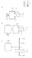
図18は、衝撃検知手段が出力した電気信号を利用して、使用者に知らせる報知手段の例を電気回路記号とブロック図で示している。   FIG. 18 shows an example of an informing means for notifying the user by using an electric signal output from the impact detecting means in an electric circuit symbol and a block diagram.

図18(a)では、衝撃検知手段11が作動すると、電気回路がON状態となり、ブザー191が作動する仕組みを例示したものである。ブザー191が作動することで、使用者は、許容値以上の衝撃が機器に生じたことを音により判断できる。なお、図示しないが、ブザー191と並列にLEDなどのライトを点灯及び点滅させることも可能かつ有用である。   FIG. 18A illustrates a mechanism in which the electric circuit is turned on and the buzzer 191 is activated when the impact detection means 11 is activated. By operating the buzzer 191, the user can determine by sound that an impact exceeding the allowable value has occurred in the device. Although not shown, it is possible and useful to turn on and blink lights such as LEDs in parallel with the buzzer 191.

図18(b)では、衝撃検知手段11が作動すると、電気回路がON状態となり、マイコン192に信号を伝える仕組みを例示したものである。マイコン192に信号が入ることで、警告音や、警告灯及び警告メッセージを通知・表示させることが可能となる。また、再度電源を入れようとした際に、チェックモードへ自動的に切替えたり、保守点検を案内するメッセージの表示をしたりすることが可能となる。   FIG. 18B illustrates a mechanism in which when the impact detection means 11 is activated, the electric circuit is turned on and a signal is transmitted to the microcomputer 192. When a signal enters the microcomputer 192, a warning sound, a warning light, and a warning message can be notified / displayed. Further, when the power is turned on again, it is possible to automatically switch to the check mode or display a message for guiding the maintenance inspection.

さらに、図18(c)では、衝撃検知手段11が作動すると、電気回路がON状態となり、さらに、装置内部の電源194を抵抗69eを用いて降圧し、マイコン192へと供給して、信号を送る仕組みを例示したものである。この場合、マイコン192に対して単独で電源を用意する必要がなく、小型化や、コストダウンにより効果的である。   Further, in FIG. 18C, when the impact detection means 11 is activated, the electric circuit is turned on. Further, the power source 194 inside the apparatus is stepped down using the resistor 69e and supplied to the microcomputer 192, and the signal is transmitted. This is an example of a sending mechanism. In this case, it is not necessary to prepare a power source for the microcomputer 192 alone, which is more effective for downsizing and cost reduction.

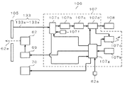
図19は、電気回路部106とその周辺のブロック図である。電気回路部106は、測定回路107と高電圧発生回路69とで構成されている。なお、穿刺装置の場合では、測定回路107、コネクタ133及び血液センサ105は不要であり、高電圧発生回路69のみ用いることになる。   FIG. 19 is a block diagram of the electric circuit unit 106 and its periphery. The electric circuit unit 106 includes a measurement circuit 107 and a high voltage generation circuit 69. In the case of the puncture device, the measurement circuit 107, the connector 133, and the blood sensor 105 are unnecessary, and only the high voltage generation circuit 69 is used.

図19において、血液センサ105の接続電極121a〜126aは、筒体102aの先端に形成されたコネクタ133(図14参照)の端子133a〜133eを介して切換回路107aに接続されている。この切換回路107aの出力は、電流/電圧変換器107bの入力に接続されている。そして、その出力はアナログ/デジタル変換器(以後、A/D変換器という)107cを介して演算部107dの入力に接続されている。この演算部107dの出力は、液晶で形成された表示部108と送信部107eに接続されている。また、切換回路107aには基準電圧源107fが接続されている。   In FIG. 19, the connection electrodes 121a to 126a of the blood sensor 105 are connected to the switching circuit 107a via terminals 133a to 133e of a connector 133 (see FIG. 14) formed at the tip of the cylindrical body 102a. The output of the switching circuit 107a is connected to the input of the current / voltage converter 107b. The output is connected to the input of the arithmetic unit 107d via an analog / digital converter (hereinafter referred to as A / D converter) 107c. The output of the calculation unit 107d is connected to a display unit 108 and a transmission unit 107e made of liquid crystal. A reference voltage source 107f is connected to the switching circuit 107a.

107gは制御部であり、この制御部107gの出力は、レーザ穿刺ユニット62に接続された高電圧発生回路69と、負圧手段70と、切換回路107aの制御端子と、演算部107dと、送信部107eとに接続されている。また、制御部107gの入力には、穿刺ボタン62aと、タイマ107kが接続されている。   Reference numeral 107g denotes a control unit, and the output of the control unit 107g is transmitted from a high voltage generation circuit 69 connected to the laser puncture unit 62, a negative pressure means 70, a control terminal of the switching circuit 107a, a calculation unit 107d, Connected to the unit 107e. Further, a puncture button 62a and a timer 107k are connected to the input of the control unit 107g.

ここで、血液センサ105は円形または回転対称の形状をしているので、単に装着したままの状態では各接続電極121a〜126aがコネクタ133a〜133fのどれと対応して接続されているか不明である。そこで、最初に、各接続電極121a〜126aの特定が行われる。この特定は、制御部107gから切換回路107aの隣り合うコネクタ133の端子133a〜133fの導通を検査して、接続電極121a〜126aを特定する。そして、接続電極126aと対応するコネクタ133の信号を直接制御部107gへ入力する。   Here, since blood sensor 105 has a circular or rotationally symmetric shape, it is unclear which connection electrode 121a to 126a is connected to which of connectors 133a to 133f in a state where it is simply attached. . Therefore, first, the connection electrodes 121a to 126a are specified. For this specification, the continuity of the terminals 133a to 133f of the adjacent connector 133 of the switching circuit 107a is inspected from the control unit 107g to specify the connection electrodes 121a to 126a. Then, the signal of the connector 133 corresponding to the connection electrode 126a is directly input to the control unit 107g.

次に、血糖値の測定について説明する。先ず、負圧手段70をオンする。そして、穿刺部104内に負圧を加え皮膚63を盛り上がらせる。これは、血液65の採取を容易にするためである。その後、穿刺ボタン62aを押下する。すると、制御部107gは高電圧発生回路69のトリガスイッチ69cをオンする。トリガスイッチ69cがオンされると、レーザ穿刺ユニット62からレーザ光62eが発射され皮膚63を穿刺する。皮膚63の穿刺により皮膚63からは血液65が滲出する。   Next, blood glucose level measurement will be described. First, the negative pressure means 70 is turned on. Then, negative pressure is applied to the puncture unit 104 to raise the skin 63. This is to facilitate the collection of blood 65. Thereafter, the puncture button 62a is pressed. Then, the control unit 107g turns on the trigger switch 69c of the high voltage generation circuit 69. When the trigger switch 69c is turned on, laser light 62e is emitted from the laser puncture unit 62 and punctures the skin 63. Blood 65 exudes from the skin 63 by puncturing the skin 63.

そして、この滲出した血液65が血液センサ105(図15、16参照)の中央部にある貯留部114に溜り、その後、毛細管効果により供給路115(図15参照)に血液65が導入される。供給路115には、検出電極121〜125(図16参照)及び試薬130が配置されており、血液65の導入により電気化学反応を起こす。血液センサ105におけるこの電気化学反応による信号をコネクタ133経由で、血液検査装置101内の測定回路107に入力し、測定・検査を行なう。   The exuded blood 65 accumulates in the reservoir 114 at the center of the blood sensor 105 (see FIGS. 15 and 16), and then the blood 65 is introduced into the supply channel 115 (see FIG. 15) by the capillary effect. Detection electrodes 121 to 125 (see FIG. 16) and a reagent 130 are arranged in the supply path 115, and an electrochemical reaction is caused by the introduction of blood 65. A signal resulting from this electrochemical reaction in the blood sensor 105 is input to the measurement circuit 107 in the blood test apparatus 101 via the connector 133 to perform measurement / test.

測定動作は、先ず、血液65が全ての検出電極121〜125へ流入しているか否かを検知する。即ち、切換回路107aを切換えて、検出電極121を電流/電圧変換器107bに接続する。また、血液65の流入を検知するための検知極となる検出電極122を基準電圧源107fに接続する。そして、検出電極121及び検出電極122間に一定の電圧を印加する。   In the measurement operation, first, it is detected whether or not the blood 65 flows into all the detection electrodes 121 to 125. That is, the switching circuit 107a is switched to connect the detection electrode 121 to the current / voltage converter 107b. Further, a detection electrode 122 serving as a detection electrode for detecting the inflow of blood 65 is connected to the reference voltage source 107f. A constant voltage is applied between the detection electrode 121 and the detection electrode 122.

この状態において、血液65が流入すると、検出電極121,122間に電流が流れる。この電流は、電流/電圧変換器107bによって電圧に変換され、その電圧値はA/D変換器107cによってデジタル値に変換される。そして、演算部107dに向かって出力される。演算部107dはそのデジタル値に基づいて血液65が十分に流入したことを検出する。   In this state, when blood 65 flows in, a current flows between detection electrodes 121 and 122. This current is converted into a voltage by the current / voltage converter 107b, and the voltage value is converted into a digital value by the A / D converter 107c. And it outputs toward the calculating part 107d. The computing unit 107d detects that the blood 65 has sufficiently flowed based on the digital value.

次に、血液成分であるグルコースの測定が行なわれる。グルコース成分量の測定は、先ず、制御部107gの指令により、切換回路107aを切換えて、グルコース成分量の測定のための作用極となる検出電極121を電流/電圧変換器107bに接続する。また、グルコース成分量の測定のための対極となる検出電極123を基準電圧源107fに接続する。   Next, glucose, which is a blood component, is measured. In the measurement of the glucose component amount, first, the switching circuit 107a is switched by a command from the control unit 107g, and the detection electrode 121 serving as a working electrode for measuring the glucose component amount is connected to the current / voltage converter 107b. In addition, a detection electrode 123 serving as a counter electrode for measuring the glucose component amount is connected to the reference voltage source 107f.

そうすると、検出電極121,123間に電流が流れる。この電流は電流/電圧変換器107bによって電圧に変換され、その電圧値はA/D変換器107cによってデジタル値に変換される。そして、演算部107dに向かって出力される。演算部107dではそのデジタル値を基にグルコース成分量に換算する。   As a result, a current flows between the detection electrodes 121 and 123. This current is converted into a voltage by the current / voltage converter 107b, and the voltage value is converted into a digital value by the A / D converter 107c. And it outputs toward the calculating part 107d. The computing unit 107d converts it into a glucose component amount based on the digital value.

グルコース成分量の測定後、Hct値の測定が行なわれる。Hct値の測定は次のように行なわれる。先ず、制御部107gからの指令により切換回路107aを切換える。そして、Hct値の測定のための作用極となる検出電極125を電流/電圧変換器107bに接続する。また、Hct値の測定のための対極となる検出電極121を基準電圧源107fに接続する。   After the measurement of the glucose component amount, the Hct value is measured. The Hct value is measured as follows. First, the switching circuit 107a is switched by a command from the control unit 107g. Then, the detection electrode 125 serving as a working electrode for measuring the Hct value is connected to the current / voltage converter 107b. Further, the detection electrode 121 serving as a counter electrode for measuring the Hct value is connected to the reference voltage source 107f.

次に、制御部107gの指令により、電流/電圧変換器107b及び基準電圧源107fから検出電極125と121間に一定の電圧を印加する。検出電極125と121間に流れる電流は、電流/電圧変換器107bによって電圧に変換され、その電圧値はA/D変換器107cによってデジタル値に変換される。そして演算部107dに向かって出力される。演算部107dはそのデジタル値に基づいてHct値に換算する。   Next, a constant voltage is applied between the detection electrodes 125 and 121 from the current / voltage converter 107b and the reference voltage source 107f according to a command from the control unit 107g. The current flowing between the detection electrodes 125 and 121 is converted into a voltage by the current / voltage converter 107b, and the voltage value is converted into a digital value by the A / D converter 107c. And it outputs toward the calculating part 107d. The computing unit 107d converts the Hct value based on the digital value.

この測定で得られたHct値とグルコース成分量を用い、予め求めておいた検量線または検量線テーブルを参照して、グルコース成分量をHct値で補正し、その補正された結果を表示部108に表示する。何れの検量線または検量線テーブルを用いるかは、血液センサ105内の識別部126に基づいて決定する。   Using the Hct value and the glucose component amount obtained in this measurement, the glucose component amount is corrected with the Hct value by referring to a calibration curve or a calibration curve table obtained in advance, and the corrected result is displayed on the display unit 108. To display. Which calibration curve or calibration curve table is used is determined based on the identification unit 126 in the blood sensor 105.

以上、グルコースの測定を例に説明したが、血液センサ105の試薬130を交換して、グルコースの測定の他に乳酸値やコレステロールの血液成分の測定にも適用できる。   Although the measurement of glucose has been described above as an example, the reagent 130 of the blood sensor 105 can be replaced, and the measurement can be applied to the measurement of blood components such as lactate and cholesterol in addition to the measurement of glucose.

以上説明したように、本実施の形態7における血液検査装置101においても実施の形態6と同様、レーザ穿刺ユニット62を用いた血液検査装置101に衝撃検知装置11を用いているので、実施の形態6と同様の効果を奏するものである。即ち、強い衝撃8aで破損された状態で使用することはなく安全である。なお、本実施の形態7においても、衝撃検知装置11を用いたが、これは衝撃検知装置31、41を用いても良い。また、衝撃検知装置51を血液検査装置101の電源スイッチと直列に接続して、強い衝撃8aが有ったとき電源を即座にオフすることもできる。   As described above, the blood test apparatus 101 according to the seventh embodiment also uses the impact detection device 11 in the blood test apparatus 101 using the laser puncture unit 62 as in the sixth embodiment. 6 has the same effect. That is, it is safe to use in a state where it is damaged by the strong impact 8a. Although the impact detection device 11 is used in the seventh embodiment, the impact detection devices 31 and 41 may be used. Further, the impact detector 51 can be connected in series with the power switch of the blood test apparatus 101, and the power can be turned off immediately when there is a strong impact 8a.

本発明にかかる衝撃検知装置は、衝撃を検知することができるので、衝撃が加わることが予想される機器、例えば血液検査装置に適用できる。   Since the impact detection apparatus according to the present invention can detect an impact, the impact detection apparatus can be applied to a device that is expected to receive an impact, such as a blood test apparatus.

本発明の実施の形態1における衝撃検知装置の説明図、(a)は同部分断面斜視図、(b)は同断面図Explanatory drawing of the impact detection apparatus in Embodiment 1 of this invention, (a) is the same fragmentary sectional perspective view, (b) is the same sectional view 本発明の実施の形態2における衝撃検知装置の断面図Sectional drawing of the impact detection apparatus in Embodiment 2 of this invention 同部分断面斜視図Partial sectional perspective view 本発明の実施の形態3における衝撃検知装置の断面図Sectional drawing of the impact detection apparatus in Embodiment 3 of this invention 同部分斜視断面図Partial perspective sectional view of the same 本発明の実施の形態4における衝撃検知装置の断面図Sectional drawing of the impact detection apparatus in Embodiment 4 of this invention 同部分断面斜視図Partial sectional perspective view 本発明の実施の形態5における衝撃検知装置の断面図、(a)は同衝撃検知装置の一例を示す断面図、(b)は同衝撃検知装置の別の一例を示す断面図Sectional drawing of the impact detection apparatus in Embodiment 5 of this invention, (a) is sectional drawing which shows an example of the impact detection apparatus, (b) is sectional drawing which shows another example of the impact detection apparatus 本発明における衝撃検知手段の斜視図及び支持体の斜視図The perspective view of the impact detection means in this invention, and the perspective view of a support body 本発明の実施の形態6における衝撃検知手段を搭載した穿刺装置の断面図Sectional drawing of the puncture apparatus carrying the impact detection means in Embodiment 6 of this invention 同穿刺装置における操作方法を説明する斜視図The perspective view explaining the operation method in the puncture device 同穿刺装置のブロック図Block diagram of the lancing device 同穿刺装置の動作フローチャートOperation flowchart of the lancing device 本発明の実施の形態7における血液検査装置の断面図Sectional drawing of the blood test apparatus in Embodiment 7 of this invention 同血液検査装置に用いる血液センサの断面図Cross-sectional view of a blood sensor used in the blood test apparatus 同血液センサの透視平面図Perspective plan view of the blood sensor 本発明における高電圧発生回路、レーザ穿刺ユニット及び衝撃検知装置とその周辺のブロック図Block diagram of a high voltage generation circuit, a laser puncture unit, an impact detection device and its surroundings 本発明における衝撃検知手段の出力を報知する手段の例を示す電気ブロック図Electric block diagram showing an example of means for notifying the output of the impact detection means in the present invention 本発明の実施の形態7における電気回路部及びその周辺のブロック図Block diagram of electric circuit section and its surroundings in Embodiment 7 of the present invention 従来の衝撃検知装置の説明図、(a)は同部分断面斜視図、(b)は同断面図Explanatory drawing of the conventional impact detection apparatus, (a) is the partial cross-sectional perspective view, (b) is the cross-sectional view

符号の説明Explanation of symbols

11、31、41、51 衝撃検知装置
12 壁部
13a、13b 支持部材
14a、14b 弾性部材
15a、15b 凹部
16a、16b 溝部
17 球体
18 衝撃検知手段
19 保存手段
21a、21b、22a、22b 電極
17b 円柱
15C 穴
15d 突起
15e 凹部
15f 突起
61 穿刺装置
101 血液検査装置
191 ブザー
192 マイコン
193 接地
194 電源
DESCRIPTION OF SYMBOLS 11, 31, 41, 51 Impact detection apparatus 12 Wall part 13a, 13b Support member 14a, 14b Elastic member 15a, 15b Recessed part 16a, 16b Groove part 17 Sphere 18 Impact detection means 19 Storage means 21a, 21b, 22a, 22b Electrode 17b Cylinder 15C hole 15d protrusion 15e recess 15f protrusion 61 puncture device 101 blood test device 191 buzzer 192 microcomputer 193 ground 194 power supply

Claims (22)

衝撃力を動力として衝撃を検知する衝撃検知手段と、この衝撃検知手段の出力を機械的に保存する保存手段とを備え、前記保存手段の出力は第1、第2の電極間の電気的な導通状態或いは非導通状態として保存される衝撃検知装置。 An impact detection means for detecting an impact using the impact force as power and a storage means for mechanically storing the output of the impact detection means are provided, and the output of the storage means is an electrical connection between the first and second electrodes. An impact detection device stored as a conductive state or a non-conductive state. 衝撃により第1、第2の電極間は電気的に導通する請求項1に記載の衝撃検知装置。 The impact detection device according to claim 1, wherein the first and second electrodes are electrically connected by an impact. 衝撃により第1、第2の電極間は電気的に絶縁される請求項1に記載の衝撃検知装置。 The impact detection device according to claim 1, wherein the first and second electrodes are electrically insulated by impact. 衝撃力を動力として衝撃を検知する衝撃検知手段と、前記衝撃検知手段が、導電体で構成され、前記導電体を挟持する少なくとも2つの支持体と、前記2つの支持体の距離を保つ為の壁部を備え、前記導電体が、前記支持体に挟持される第一の位置から前記支持体と前記壁部との間の第2の位置に移動可能であり、かつ前記導電体が前記第一の位置又は前記第二の位置で電気的な導通と非導痛が切り替わることを特徴とする衝撃検知装置。 An impact detection means for detecting an impact using an impact force as power, and the impact detection means is made of a conductor, and maintains at least a distance between the two supports and at least two supports sandwiching the conductor. A wall portion, wherein the conductor is movable from a first position sandwiched by the support to a second position between the support and the wall, and the conductor is the first An impact detection device, wherein electrical conduction and non-conduction are switched at one position or the second position. 前記導電体を挟持する少なくとも2つの支持体に、前記導電体と導通する少なくとも2つの電極を備えた請求項4に記載の衝撃検知装置。 The impact detection device according to claim 4, wherein at least two electrodes that are electrically connected to the conductor are provided on at least two supports that sandwich the conductor. 前記導電体を挟持する少なくとも2つの支持体の距離を保つ為の前記壁部に設けられた第1の電極と前記壁部と前記支持体との間に第2の電極を配置した請求項4に記載の衝撃検知装置。 The second electrode is disposed between the first electrode provided on the wall and the wall and the support for maintaining a distance between at least two supports that sandwich the conductor. The impact detection apparatus described in 1. 前記支持体の導電体を支持する少なくとも一つの部位が、弾性体で構成された請求項4に記載の衝撃検知装置。 The impact detection device according to claim 4, wherein at least one portion of the support that supports the conductor is made of an elastic body. 前記支持体に備えた前記少なくとも一つの弾性体が、前記導電体側に開口した凹みを有する請求項4に記載の衝撃検知装置。 The impact detection apparatus according to claim 4, wherein the at least one elastic body provided in the support body has a recess opened on the conductor side. 前記導電体の表面に少なくとも一つの凹みを備え、前記支持体に備えた前記少なくとも一つの弾性体が、凸形状を有し、前記導電体の前記凹み部と前記支持体の前記弾性体の凸部とが一致して挟持された、請求項4に記載の衝撃検知装置。 The surface of the conductor is provided with at least one recess, and the at least one elastic body provided on the support has a convex shape, and the recess of the conductor and the protrusion of the elastic body of the support are provided. The impact detection device according to claim 4, wherein the impact detection device is sandwiched by being coincident with the portion. 前記導体を挟持する支持体が、少なくとも一つの弾性体で付勢され、前記導電体を挟持する請求項4に記載の衝撃検知装置。 The impact detection device according to claim 4, wherein the support body for sandwiching the conductor is biased by at least one elastic body to sandwich the conductor. 前記壁部と前記支持体との間に導電体を保持する溝を設けた請求項4に記載の衝撃検知装置。 The impact detection device according to claim 4, wherein a groove for holding a conductor is provided between the wall portion and the support. 前記溝部の底部に第二の電極を配したことを特徴とする請求項11に記載の衝撃検知装置。 The impact detection device according to claim 11, wherein a second electrode is disposed on a bottom portion of the groove portion. 衝撃により、前記少なくとも2つの支持体の電極間が絶縁される請求項4に記載の衝撃検知装置。 The impact detection device according to claim 4, wherein an electrode between the at least two supports is insulated by an impact. 衝撃により、前記導電体を挟持する少なくとも2つの支持体の距離を保つ為の前記壁部に設けられた第1の電極と前記壁部と前記支持体との間に第2の電極が導通する請求項4に記載の衝撃検知装置。 Due to the impact, the second electrode is electrically connected between the first electrode provided on the wall for maintaining the distance between the at least two supports sandwiching the conductor, and the wall and the support. The impact detection apparatus according to claim 4. 前記検知手段が、概略球体である、請求項1または4に記載の衝撃検知装置。 The impact detection device according to claim 1, wherein the detection unit is a substantially spherical body. 前記検知手段が、概略円筒である、請求項1または4に記載の衝撃検知装置。 The impact detection apparatus according to claim 1, wherein the detection unit is a substantially cylindrical shape. 穿刺装置の筐体の一方に設けられた穿刺部と、この穿刺部に対向して設けられたレーザ穿刺ユニットと、このレーザ穿刺ユニットを駆動する高電圧発生回路とを備え、前記筐体内に請求項1に記載の衝撃検知装置が装着されるとともに、前記高電圧発生回路を形成するコンデンサの両端に前記衝撃検知装置の少なくとも2つの電極が夫々接続された穿刺装置。 A puncturing section provided on one side of the casing of the puncturing apparatus, a laser puncturing unit provided opposite to the puncturing section, and a high voltage generation circuit for driving the laser puncturing unit, and being charged in the casing A puncture device to which the impact detection device according to item 1 is mounted and at least two electrodes of the impact detection device are respectively connected to both ends of a capacitor forming the high voltage generation circuit. 衝撃検知装置を複数有する、請求項17に記載の穿刺装置。 The puncture device according to claim 17, comprising a plurality of impact detection devices. 前記複数の衝撃検知装置は、それぞれ90度の相対角度を有して配置されている請求項18に記載の穿刺装置。 The puncture apparatus according to claim 18, wherein each of the plurality of impact detection apparatuses is disposed with a relative angle of 90 degrees. 血液検査装置の筐体の一方を形成する筒体へ着脱自在に装着されたホルダと、このホルダに形成された穿刺部と、前記筒体と前記ホルダとの間に装着される血液センサと、この血液センサに接続される電気回路部と、この電気回路部を構成する高電圧発生回路と、この高電圧発生回路に接続されるとともに前記穿刺部に対向して設けられたレーザ穿刺ユニットとを備え、前記筐体内に請求項1に記載の衝撃検知装置が装着されるとともに、前記高電圧発生回路を形成するコンデンサの両端に前記衝撃検知装置の少なくとも2つの電極が夫々接続された血液検査装置。 A holder detachably attached to a cylinder forming one of the housings of the blood test apparatus, a puncture portion formed in the holder, a blood sensor attached between the cylinder and the holder, An electrical circuit unit connected to the blood sensor, a high voltage generation circuit constituting the electrical circuit unit, and a laser puncture unit connected to the high voltage generation circuit and provided facing the puncture unit And a blood test apparatus in which the shock detection device according to claim 1 is mounted in the housing, and at least two electrodes of the shock detection device are respectively connected to both ends of a capacitor forming the high voltage generation circuit. . 衝撃検知装置を複数有する、請求項20に記載の血液検査装置。 The blood test apparatus according to claim 20, comprising a plurality of impact detection apparatuses. 前記複数の衝撃検知装置は、それぞれ90度の相対角度を有して配置されている請求項21に記載の血液検査装置。 The blood test apparatus according to claim 21, wherein each of the plurality of impact detection apparatuses is arranged with a relative angle of 90 degrees.
JP2008320445A 2008-12-17 2008-12-17 Impact detector, and puncture device and blood tester using the impact detector Pending JP2010142316A (en)

Priority Applications (1)

Application Number Priority Date Filing Date Title
JP2008320445A JP2010142316A (en) 2008-12-17 2008-12-17 Impact detector, and puncture device and blood tester using the impact detector

Applications Claiming Priority (1)

Application Number Priority Date Filing Date Title
JP2008320445A JP2010142316A (en) 2008-12-17 2008-12-17 Impact detector, and puncture device and blood tester using the impact detector

Publications (1)

Publication Number Publication Date
JP2010142316A true JP2010142316A (en) 2010-07-01

Family

ID=42563376

Family Applications (1)

Application Number Title Priority Date Filing Date
JP2008320445A Pending JP2010142316A (en) 2008-12-17 2008-12-17 Impact detector, and puncture device and blood tester using the impact detector

Country Status (1)

Country Link
JP (1) JP2010142316A (en)

Cited By (1)

* Cited by examiner, † Cited by third party
Publication number Priority date Publication date Assignee Title
KR101374204B1 (en) * 2012-10-31 2014-03-14 대한민국 Impact detection device

Cited By (1)

* Cited by examiner, † Cited by third party
Publication number Priority date Publication date Assignee Title
KR101374204B1 (en) * 2012-10-31 2014-03-14 대한민국 Impact detection device

Similar Documents

Publication Publication Date Title
US7676945B2 (en) Modular measurement probe
US11703313B2 (en) Detection device for detecting a deformation of a housing of a high-voltage accumulator of a motor vehicle
CN101404933B (en) blood test device
JP5837784B2 (en) Apparatus and method for determining safety of battery pack
JP4996596B2 (en) Blood test equipment
CN103354901B (en) Biological sample measuring device
CN101404936A (en) Blood test device and control method thereof
CN101404934B (en) Laser perforation device
US9068900B2 (en) Deflection sensitive coolant activated drain plug detection system for high voltage battery packs
US9234970B2 (en) Portable radiation dosimeter
CN111180812A (en) Battery module, assembling method thereof and leakage detection method
US8439848B2 (en) Blood testing device
JP2014192104A (en) Battery
WO2019171983A1 (en) Battery holder and sensor unit
JP2009118969A5 (en)
KR101920910B1 (en) Resistance measurement system comprising probe including display unit
EP3336956B1 (en) Method for monitoring a discharge device of a battery
JP3423403B2 (en) Ophthalmic instruments
JP2010099107A (en) Blood testing device
CN217138043U (en) Noninvasive neonatal jaundice detection device based on laser
JP5011935B2 (en) Blood test equipment
JP2010178819A (en) Puncture device and blood examination apparatus using the same
KR200433455Y1 (en) Glucose extraction patch and bloodless blood glucose measurement apparatus including the same
JP2016070705A (en) Component measuring device
JP2012190601A (en) Secondary battery