JP2010142363A - Medical valve - Google Patents
Medical valve Download PDFInfo
- Publication number
- JP2010142363A JP2010142363A JP2008321179A JP2008321179A JP2010142363A JP 2010142363 A JP2010142363 A JP 2010142363A JP 2008321179 A JP2008321179 A JP 2008321179A JP 2008321179 A JP2008321179 A JP 2008321179A JP 2010142363 A JP2010142363 A JP 2010142363A
- Authority
- JP
- Japan
- Prior art keywords
- valve
- state
- fluid passage
- hole
- valve body
- Prior art date
- Legal status (The legal status is an assumption and is not a legal conclusion. Google has not performed a legal analysis and makes no representation as to the accuracy of the status listed.)
- Pending
Links
Images








Landscapes
- Media Introduction/Drainage Providing Device (AREA)
- Infusion, Injection, And Reservoir Apparatuses (AREA)
Abstract
【課題】簡単且つコンパクトな構造によって、遮断状態から連通状態への切換えを高い信頼性で確実に実現することが出来る医療用弁を、提供する。
【解決手段】弾性体からなる弁本体54を備えていると共に、弁本体54には軸方向に貫通する作用孔70が形成されており、弁本体54の流体通路への配設状態下で作用孔70と弁本体54の外周面上との少なくとも一方によって流体通路を連通状態とする連通路が形成されるようになっている。一方、作用孔70への内挿と外周面への外挿との何れかによって、作用部材56が弁本体54に組み付けられている。この作用部材56は、弁本体54に対して軸直角方向の嵌合外力を及ぼすことにより連通路を消失させて流体通路を遮断状態に保持すると共に、弁本体54に対して軸方向で相対変位させられることによって弁本体54に対する嵌合外力を解除して連通路を連通状態に切り換える。
【選択図】図5To provide a medical valve capable of reliably and reliably switching from a shut-off state to a communication state by a simple and compact structure.
A valve main body 54 made of an elastic body is provided, and an action hole 70 penetrating in the axial direction is formed in the valve main body 54, and the valve main body 54 operates in a state of being disposed in a fluid passage. A communication passage that makes the fluid passage communicate with each other is formed by at least one of the hole 70 and the outer peripheral surface of the valve body 54. On the other hand, the action member 56 is assembled to the valve body 54 by either insertion into the action hole 70 or extrapolation to the outer peripheral surface. The action member 56 exerts a fitting external force in a direction perpendicular to the axis on the valve body 54 to eliminate the communication path and keep the fluid path in a shut-off state. As a result, the external force applied to the valve body 54 is released, and the communication path is switched to the communication state.
[Selection] Figure 5
Description
本発明は、例えば医療用カテーテル等の各種医療用器具や装置に形成されて薬液や血液等の流体を流通させる流体通路に装着される医療用弁に関するものである。 The present invention relates to a medical valve that is formed in various medical instruments and devices such as a medical catheter and is attached to a fluid passage through which a fluid such as a drug solution or blood flows.
医療分野で用いられる各種器具や装置には、種々の薬液や血液、ガス等を流通させる流体通路を備えたものが多くある。例えば、患者に輸液や採血等を行う際には、カテーテルやチューブ,シリンジ等を用いて流体通路としての液ラインを形成し、この液ラインを通じて輸液や採血が行われる。 Many instruments and devices used in the medical field are provided with fluid passages through which various chemical solutions, blood, gas, and the like circulate. For example, when performing infusion, blood collection, or the like on a patient, a liquid line as a fluid passage is formed using a catheter, tube, syringe, or the like, and infusion or blood collection is performed through the liquid line.
ところで、これらの液ラインには、流体通路を制御するために医療用弁が装着されることが多い。例えば、血管に穿刺されるカテーテル等では、血液や輸液の漏れを防止する等の目的で、液ラインを連通状態と遮断状態に切り換える医療用弁が用いられる。具体的には、例えば特許文献1に記載の止血弁が、それである。 By the way, a medical valve is often attached to these liquid lines in order to control the fluid passage. For example, in a catheter or the like that is punctured into a blood vessel, a medical valve that switches a liquid line between a communication state and a blocking state is used for the purpose of preventing leakage of blood or infusion. Specifically, for example, the hemostatic valve described in Patent Document 1 is the same.
しかしながら、特許文献1に記載の如き従来構造の医療用弁には、未だ改良の余地があった。即ち、これらの医療用弁は、外力が作用しない単体状態での初期形状が流体通路を遮断するようになっており、内針ハブ等の他部材で外力を加えて医療用弁を弾性変形させることにより、流体通路が連通状態に切り換えられるようになっている。それ故、医療用弁を本来の初期形状から確実に且つ充分に変形させなければ流体通路が連通状態に切り換えらないのであり、そのために、連通状態への切換作動への確実性と信頼性を充分に得難い場合があった。 However, there is still room for improvement in the conventional medical valve as described in Patent Document 1. That is, in these medical valves, the initial shape in a single state where no external force is applied blocks the fluid passage, and the medical valve is elastically deformed by applying an external force with another member such as an inner needle hub. Thus, the fluid passage can be switched to the communication state. Therefore, unless the medical valve is reliably and sufficiently deformed from the original initial shape, the fluid passage cannot be switched to the communication state. Therefore, the reliability and reliability of the switching operation to the communication state is improved. In some cases, it was difficult to obtain.
加えて、これら従来構造の医療用弁では、輸液や採血の期間に亘って流体通路を連通状態に保持し続けるに際して、医療用弁に一定の外力を安定して及ぼし続ける必要がある。それ故、特に長時間の輸液等に際しては、流体通路を連通状態に保持し続けることの確実性と信頼性の確保が一層難しくなる。 In addition, in these conventional medical valves, it is necessary to stably apply a certain external force to the medical valve when the fluid passage is kept in communication for the period of infusion or blood collection. Therefore, particularly in the case of infusion for a long time, it becomes more difficult to ensure the reliability and reliability of keeping the fluid passage in a communicating state.
特に、医療用の流体通路では、目的とする薬液等の患者への供給が確実に行われないと重大な結果を招くおそれがあることから、医療用弁における連通状態への確実な切換作動が要求されることが多い。かかる観点からも、従来構造の医療用弁には、遮断状態から連通状態への切換え及び連通状態への保持に関して、その作動の確実性および信頼性の更なる向上が必要とされるのである。 In particular, in a medical fluid passage, if a target drug solution or the like is not reliably supplied to a patient, a serious result may be caused. Often required. From this point of view, the medical valve having the conventional structure is required to further improve the reliability and reliability of the operation with respect to switching from the shut-off state to the communication state and maintaining the communication state.
ここにおいて、本発明は、上述の如き事情を背景として為されたものであって、その解決課題とするところは、遮断状態から連通状態への切換え及び連通状態への保持を一層高い信頼性をもって確実に行うことの出来る、改良された医療用弁を提供することにある。 Here, the present invention has been made in the background as described above, and the problem to be solved is to switch from the shut-off state to the communication state and to maintain the communication state with higher reliability. The object is to provide an improved medical valve that can be reliably performed.
本発明は、医療用の器具や装置に設けられた流体通路に装着されてこの流体通路を連通状態と遮断状態に切り換える医療用弁であって、流体通路に配設される弾性体からなる弁本体を備えていると共に、かかる弁本体には流体通路の通路長方向となる軸方向に貫通する作用孔が形成されており、弁本体の流体通路への配設状態下で作用孔と弁本体の外周面上との少なくとも一方によって流体通路を連通状態とする連通路が形成されるようになっている一方、弁本体における作用孔への内挿と外周面への外挿との何れかによって組み付けられて、弁本体に対して外周側又は内周側への嵌合外力を及ぼすことにより、かかる連通路を消失させて流体通路を遮断状態に保持すると共に、弁本体に対して軸方向で相対変位させられることによって弁本体に対する嵌合外力を解除して流体通路を連通状態とする作用部材を設けた医療用弁を、構成上の特徴とする。 The present invention is a medical valve that is mounted on a fluid passage provided in a medical instrument or device and switches the fluid passage between a communication state and a shut-off state, and is a valve made of an elastic body disposed in the fluid passage. The valve body is provided with a working hole penetrating in the axial direction, which is the passage length direction of the fluid passage, and the working hole and the valve body are arranged in a state where the valve body is disposed in the fluid passage. On the other hand, at least one of the outer peripheral surface and the outer peripheral surface of the fluid passage is in communication with the fluid passage. On the other hand, the valve body is inserted into the working hole or extrapolated to the outer peripheral surface. As a result, by applying a fitting external force to the outer peripheral side or inner peripheral side of the valve main body, the communication passage is lost and the fluid passage is held in a shut-off state. Valve book by being relatively displaced To release the engagement force against the medical valve having a working member to the fluid passage in the communicating state, characterized in configuration.
[本発明の作用・効果]
本発明に従う構造の医療用弁では、外力が作用していない状態で流体通路が連通状態とされる。それ故、作用部材を介して弁体に及ぼされている外力を取り除くことにより、流体通路を確実に連通状態とし、更に安定して連通状態に保持することが出来る。しかも、流体通路の連通状態への保持が、外力を必要とすることなく弁本体そのもので実現されることから、流体通路を連通状態に保持するための特別な部材も必要なく、簡単で且つコンパクトな構造が実現可能となる。
[Operation and effect of the present invention]
In the medical valve having the structure according to the present invention, the fluid passage is in a communication state in a state where no external force is acting. Therefore, by removing the external force exerted on the valve body via the action member, the fluid passage can be reliably brought into a communication state, and can be stably maintained in a communication state. In addition, since the fluid passage can be maintained in the communication state with the valve body itself without requiring an external force, no special member for holding the fluid passage in the communication state is required, and it is simple and compact. A simple structure can be realized.
加えて、本発明に係る医療用弁では、弁本体に外力を及ぼして流体通路を閉鎖する作用部材を軸方向に変位させることで流体通路が遮断状態から連通状態に切り換えられるようになっている。それ故、例えば流体通路を構成する管路を差し入れて接続するのと同時に、かかる管路を利用して作用部材を軸方向に変位させて流体通路を遮断状態から連通状態に切り換えることが可能であり、それによって、切換構造と切換操作の簡略化も達成され得る。 In addition, in the medical valve according to the present invention, the fluid passage is switched from the shut-off state to the communication state by displacing an action member that applies an external force to the valve body to close the fluid passage in the axial direction. . Therefore, for example, at the same time as inserting and connecting the pipes constituting the fluid passage, it is possible to switch the fluid passage from the cut-off state to the communication state by displacing the action member in the axial direction using the pipe passage. Yes, thereby simplifying the switching structure and switching operation.
[本発明のその他の態様と効果]
なお、上述の構成上の特徴を備えた本発明では、以下の何れかの態様を、必要に応じて適宜に組み合わせて採用することが可能である。
[Other aspects and effects of the present invention]
In the present invention having the above-described structural features, any one of the following aspects can be appropriately combined as necessary.
例えば、本発明は、弁本体の作用孔によって連通路が形成されるようになっている一方、作用部材が筒形状とされて弁本体に外挿されて組み付けられていると共に、作用部材には内周面上に突出する環状の作用突部が形成されており、かかる作用突部が弁本体の外周面に押し付けられて弁本体に対して内周側への嵌合外力を及ぼすことにより弁本体が縮径変形して該作用孔が遮断されるようになっている構成が、採用され得る。 For example, in the present invention, the communication passage is formed by the action hole of the valve body, while the action member has a cylindrical shape and is assembled by being externally attached to the valve body. An annular working protrusion projecting on the inner peripheral surface is formed, and the working protrusion is pressed against the outer peripheral surface of the valve main body to exert a fitting external force on the inner peripheral side against the valve main body. A configuration in which the diameter of the main body is reduced to block the working hole can be adopted.
また、そのような筒形状の作用部材を採用するに際しては、弁本体の外周面には段差を軸方向に挟んで大径部分と小径部分を形成すると共に、作用部材の作用突部をそれら大径部分と小径部分との間で軸方向に移動可能として、作用突部が大径部分の外周面上に位置させられて大径部分が作用突部で縮径変形されることによって作用孔が潰されて遮断されるようにする一方、作用突部が小径部分の外周面上に移動させられることで作用孔が連通状態に切り換えられるようにすることが、好適である。このような構成を採用すれば、弁本体に対する作用部材の外挿組付状態を維持しつつ、弁本体に対して作用部材を軸方向で相対移動させることにより連通路を連通状態と遮断状態に切り換えることが出来る。 Further, when adopting such a cylindrical action member, a large diameter portion and a small diameter portion are formed on the outer peripheral surface of the valve body with a step in the axial direction, and the action protrusions of the action member are made large in size. The working hole is movable in the axial direction between the diameter portion and the small diameter portion, and the working protrusion is positioned on the outer peripheral surface of the large diameter portion, and the large diameter portion is reduced in diameter by the working protrusion, thereby forming the working hole. While being crushed and shut off, it is preferable that the working projection is moved onto the outer peripheral surface of the small-diameter portion so that the working hole is switched to the communication state. By adopting such a configuration, the communication path is brought into the communication state and the cutoff state by moving the action member relative to the valve body in the axial direction while maintaining the externally assembled state of the action member with respect to the valve body. Can be switched.
さらに、本発明では、作用孔を弁本体の中心軸上を貫通して形成した構成が、採用され得る。弁本体の中心軸上に作用孔を形成することにより、例えば留置針組立体の外針ハブ内に弁本体を装着してその作用孔に内針を挿通させること等も可能となる。 Furthermore, in the present invention, a configuration in which the working hole is formed so as to penetrate the central axis of the valve body can be employed. By forming the action hole on the central axis of the valve body, for example, the valve body can be mounted in the outer needle hub of the indwelling needle assembly and the inner needle can be inserted through the action hole.
また、本発明では、作用孔における長さ方向の中間部分に小径化された狭窄部を形成し、この狭窄部が形成された長さ方向の中間部分に対して作用部材による嵌合外力が及ぼされることによって流体通路の遮断状態と連通状態が選択的に生ずるようにした構成が、採用され得る。このような構成を採用すれば、例えば作用孔を連通路として利用する場合には、狭窄部で作用孔を遮断し易くできると共に、作用孔の開口部を非狭窄部としたことで流体圧力を非狭窄部から狭窄部に導いて、作用孔を一層確実に連通状態とすることが出来る。また、作用孔に作用部材を挿通させてを閉鎖させる場合には、非狭窄部とされた作用孔の開口部から作用部材を容易に挿入することが出来る。 In the present invention, a narrowed portion having a reduced diameter is formed in an intermediate portion in the length direction of the working hole, and an external force applied by the working member is exerted on the intermediate portion in the length direction in which the narrowed portion is formed. Therefore, a configuration in which the shut-off state and the communication state of the fluid passage are selectively generated can be adopted. If such a configuration is employed, for example, when the working hole is used as a communication path, the working hole can be easily blocked at the narrowed portion, and the fluid pressure can be reduced by making the opening portion of the working hole non-stenotic portion. It is possible to guide the working hole from the non-stenosis part to the stenosis part and to make the working hole more reliably communicated. Further, when the working member is inserted into the working hole and closed, the working member can be easily inserted from the opening portion of the working hole which is a non-constricted portion.
また、本発明の医療用弁は、薬液等の流体通路の接続部分を構成する雌雄コネクタによる連結部位にも好適に装着される。その場合には、例えば、筒状の雌コネクタに対して弁本体および作用部材が収容状態で組み付けられると共に、雌コネクタに雄コネクタが挿し込まれることによって作用部材が雄コネクタで押されて弁本体に対して軸方向に相対変位させられて、作用部材が弁本体に対して嵌合外力を及ぼして流体流路を遮断状態に保持する位置から弁本体に対する嵌合外力を解除して流体流路を連通状態とする位置まで変位するようにした構造が、好適に採用され得る。 In addition, the medical valve of the present invention is also suitably attached to a connecting portion by a male and female connector that constitutes a connecting portion of a fluid passage such as a chemical solution. In that case, for example, the valve main body and the action member are assembled in the accommodated state with respect to the cylindrical female connector, and the male connector is inserted into the female connector so that the action member is pushed by the male connector and the valve main body The fluid flow passage is released from the position where the acting member exerts a fitting external force on the valve body to hold the fluid flow path in a shut-off state relative to the valve body. A structure that can be displaced to a position where is in a communicating state can be suitably employed.
また、本発明の医療用弁は、留置針組立体にも好適に装着される。かかる留置針組立体の構造は、一般に、先端から突出する内針を備えた内針ハブと先端から突出する外針を備えた外針ハブとを含んで構成されており、外針ハブの基端側開口部から内針を差し入れて内針を外針に挿通させた状態で内針ハブの先端部分が外針ハブの基端部分に組み付けられた構造とされる。そして、この留置針組立体に対して本発明の医療用弁を装着するに際しては、例えば、弁本体が外針ハブに収容状態で装着されると共に、弁本体に組み付けられた作用部材が外針ハブ内で弁本体から基端側開口部に向かって筒状に延び出して、内針ハブの内針が作用部材および弁本体の作用孔から外針にまで挿通された構造が、好適に採用され得る。なお、このように医療用弁を装着した留置針組立体においては、外針ハブから内針ハブを分離させることで弁本体の連通路としての作用孔から内針が抜き取られて、弁本体の流体通路としての連通路が遮断状態となる。その後、例えば、外針ハブにカテーテルチップを挿入することで、作用部材がカテーテルチップで押圧されて弁本体に対して軸方向で相対変位させられることで弁本体の連通路ひいては流体通路が連通状態とされることとなる。 In addition, the medical valve of the present invention is also suitably attached to an indwelling needle assembly. Such an indwelling needle assembly generally includes an inner needle hub having an inner needle protruding from the distal end and an outer needle hub having an outer needle protruding from the distal end. The distal end portion of the inner needle hub is assembled to the proximal end portion of the outer needle hub in a state where the inner needle is inserted from the end opening and the inner needle is inserted through the outer needle. When the medical valve according to the present invention is mounted on the indwelling needle assembly, for example, the valve body is mounted in the housing state in the outer needle hub, and the action member assembled to the valve body is the outer needle. A structure in which the inner needle of the inner needle hub extends from the valve body toward the proximal end opening in the hub and the inner needle of the inner needle hub is inserted from the working hole of the working member and the valve body to the outer needle is preferably used. Can be done. In the indwelling needle assembly equipped with the medical valve in this way, the inner needle is removed from the working hole as the communication passage of the valve body by separating the inner needle hub from the outer needle hub, and the valve body The communication path as the fluid path is cut off. After that, for example, by inserting the catheter tip into the outer needle hub, the action member is pressed by the catheter tip and is displaced relative to the valve body in the axial direction, so that the communication passage of the valve body and thus the fluid passage is in communication. Will be taken.
以下、本発明の実施形態について、図面を参照しつつ、詳細に説明する。 Hereinafter, embodiments of the present invention will be described in detail with reference to the drawings.
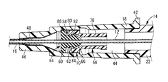
先ず、図1には、本発明に係る医療用弁の第一の実施形態である弁機構10を備えた、留置針組立体が示されている。留置針組立体は、中空の内針12が先端から突設された内針ハブ14と、中空の外針16が先端から突設された雌コネクタとしての外針ハブ18とを備えている。なお、本実施形態では、図1中の右側を基端側といい、図1中の左側を先端側という。
First, FIG. 1 shows an indwelling needle assembly including a
内針ハブ14は、ハブ本体22を有している。ハブ本体22は、略円筒形状の周壁を有しており、その内孔が基部側に開口している。また、ハブ本体22の先端部には貫通孔28が形成されており、この貫通孔28に対して内針12が挿通固定されている。なお、内針ハブ14の基端部側の開口部には、通気フィルタ30を備えたキャップ38が装着されている。このキャップ38の装着により、内針ハブ14の内部には血液貯留空間40が形成されている。
The inner needle hub 14 has a
一方、外針ハブ18も、内針ハブ14と同様に、略円筒形状の周壁を有しており、その内孔が基端側に開口している。この外針ハブ18の内孔が、中空部としての収容部44とされている。なお、内孔の基端側開口部には、外フランジ状の螺合部42が一体形成されている。また、外針ハブ18の先端部46には貫通孔48が形成されており、この貫通孔48に対して外針16が挿通固定されている。なお、本実施形態における流体通路は、外針16及び外針ハブ18の各内孔を含んで構成されている。
On the other hand, similarly to the inner needle hub 14, the
そして、図1及び図2に示されるように、外針ハブ18の基端側開口部に対して内針ハブ14の先端部分が嵌め合わされて組み付けられている。かかる組付状態下では、内針12が外針16に挿通されて、外針16の先端から内針12の先端が突出している。
As shown in FIGS. 1 and 2, the distal end portion of the inner needle hub 14 is fitted and assembled to the proximal end side opening portion of the
さらに、外針ハブ18には、収容部44に弁機構10が装着されている。この弁機構10は、弁本体としての止血弁54と、作用部材としての押し子56を含んで構成されている。かかる弁機構10によって、流体通路を構成する収容部44が、連通状態と遮断状態に切り換えられるようになっている。
Further, the
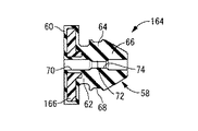
止血弁54は、図3に示されているように、略円柱形状の弁部58と、該弁部58の先端側端部(図3中、左端部)において外周側に向かって突出するフランジ形状の支持部60とを有している。これら弁部58と支持部60を有する止血弁54は、ゴム弾性体や合成樹脂(エラストマ)等の弾性変形可能な材質で一体成形されている。
As shown in FIG. 3, the
弁部58は、軸方向中間部分の外周面に段差61が形成された段付きの略円柱形状を有している。段差61を挟んで、支持部60側(図3中の左側)が小径部62とされていると共に、反対側(図3中の右側)が大径部64とされている。弁部58において、小径部62側の軸方向端部は、支持部60と一体的に繋がっている。また、大径部64には、外周面上を全周に亘って延びる係止凹溝68が形成されている。なお、この係止凹溝68の外径は、小径部62の外径よりも大きい。また、弁部58において、大径部64側の軸方向端部は、外周面が次第に細くなるテーパ形状の案内部66とされている。
The
また、止血弁54には、作用孔としての連通孔70が貫通形成されている。この連通孔70は、小径の円形断面を有しており、止血弁54の中心軸上を延びている。また、連通孔70の長さ方向中間部分には、内周面上にシール突部72が形成されている。そして、連通孔70は、このシール突部72の形成された長さ方向中間部分が、両端部分よりも小径化された狭窄部74となっている。また、かかる狭窄部74は、止血弁54の軸方向で、係止凹溝68と略同じ位置に形成されている。なお、狭窄部74の内周面と、その軸方向両側の大径部分との境界は、次第に径寸法が変化するテーパ状内周面で接続されている。
The
一方、押し子56は、図4に示されているように、略円筒形状をもって硬質材料で形成されている。また、押し子56の軸方向中間部分には、段差状のテーパ部76が設けられており、このテーパ部76を挟んで基端側(図4中の右側)が小径筒部78とされていると共に、反対の先端側が大径筒部80とされている。なお、押し子56の形成材料は、特に限定されるものではないが、例えば、ポリプロピレン,ポリカーボネート,ポリ塩化ビニル,ポリスチレン,ポリアセタール等が、好適に採用される。
On the other hand, as shown in FIG. 4, the
また、押し子56には、大径筒部80側の先端部内周面に、環状の作用突部82が一体形成されている。そして、大径筒部80の内径寸法が、止血弁54の大径部64において係止凹溝68を外れた部分の外径寸法と略同じかそれより大きくされている。一方、作用突部82の内径寸法は、止血弁54の大径部64に形成された係止凹溝68の底部外径よりも小さくされている。また、作用突部82の内径寸法は、止血弁54の小径部62の外径寸法と略同じかそれよりも大きく設定されている。
The
そして、図5に示されているように、押し子56は、止血弁54の弁部58に対して外挿状態で組み付けられている。かかる組付状態下、押し子56の大径筒部80内に、弁部58が案内部66側から差し入れられている。
As shown in FIG. 5, the
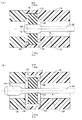
また、押し子56は、止血弁54に対して軸方向で相対変位可能とされている。図5(a)に示されているように、弁部58の大径部64上に、押し子56の作用突部82が位置合わせされた状態下では、弁部58に対して径方向内向きの嵌合外力が及ぼされて、弁部58の大径部64が縮径変形されている。そして、弁部58の弾性変形によって、連通孔70の内周側に突出するシール突部72の突出先端部分が、縮径変位せしめられて互いに当接せしめられる。これにより、止血弁54に貫通形成された連通孔70が、狭窄部74の形成部位で押し潰されて、遮断状態に保持されている。なお、押し子56の作用突部82は、係止凹溝68への係合作用で、大径部64上に安定して位置決めされるようになっている。
Further, the
一方、図5(b)に示されているように、押し子56の先端部分を弁部58の奥方まで軸方向に押し込むことにより、押し子56の作用突部82を弁部58の大径部64から離脱させて小径部62上に位置合わせさせることが出来る。この図5(b)に示された状態下では、押し子56の作用突部82による弁部58に対する嵌合外力が解除されて、弁部58が初期形状に向けて復元し、連通孔70が連通状態に切り換えられて保持される。
On the other hand, as shown in FIG. 5B, by pushing the tip portion of the
なお、図5(b)に示されている連通孔70の連通状態では、押し子56のテーパ部76が弁部58の案内部66に当接することで、弁部58の予期しない変形が防止されるようになっている。これにより、連通孔70の連通状態が一層安定して保持されるようになっている。
In the communication state of the
上述の構造とされた弁機構10は、図6に示されているように、外針ハブ18の収容部44内の先端部分に収容装着される。かかる装着状態下、止血弁54は、その支持部60が収容部44内の先端部分に嵌め込まれており、支持部60の外周面が収容部44の内周面に対して密着状態で組み付けられている。なお、支持部60の軸方向先端側(図6中の左側)の面は、その外周縁部が、外針ハブ18の収容部44に形成された段差面86に当接されている。これにより、外針ハブ18の収容部44内での止血弁54の軸方向先端側への移動が阻止されて位置決めされている。また、止血弁54に組み付けられた押し子56は、収容部44内において、止血弁54から基端側(図6中の右側)に向かって突出している。なお、押し子56の大径筒部80の外周面は、収容部44の内周面に対して軸方向でスライド変位可能に嵌め合わされている。
As shown in FIG. 6, the
そして、留置針組立体に本発明を適用した本実施形態では、上述のように弁機構10を装着した外針ハブ18に対して、図1,2に示されているように内針ハブ14を組み付けることにより、止血弁54の連通孔70に対して内針12が挿通される。このように内針ハブ14と外針ハブ18を組み付けた状態下では、押し子56の作用突部82の嵌合外力で遮断状態とされた止血弁54の連通孔70に内針12が強制的に挿通されることで、内針12の外周面が止血弁54の連通孔70の内周面に密着されている。
In the present embodiment in which the present invention is applied to the indwelling needle assembly, the inner needle hub 14 as shown in FIGS. 1 and 2 with respect to the
上述の構造とされた本実施形態の留置針組立体は、特許文献1に示されている従来構造のものと略同様に使用することが出来る。 The indwelling needle assembly of this embodiment having the above-described structure can be used in substantially the same manner as that of the conventional structure shown in Patent Document 1.
その使用態様を例示する。先ず、図1,2に示されている如き留置針組立体を用いて、内針12と外針16を患者の血管に穿刺した後、内針ハブ14を外針ハブ18から引き抜いて内針12を抜去する。これにより、図6に示されているように、外針16の留置状態が実現される。
The usage mode is illustrated. First, the indwelling needle assembly as shown in FIGS. 1 and 2 is used to puncture the patient's blood vessel with the
かかる操作に際して、止血弁54の連通孔70から内針12が抜き取られると、押し子56の作用突部82で止血弁54の大径部64に及ぼされている締付力により、連通孔70が速やかに押し潰されて遮断状態に保持される。要するに、図6に示された状態下において、内針12の挿通で強制的に拡径された連通孔70が、内針12の抜き取りによって遮断状態となる。
In this operation, when the
次に、図7に示されているように、外針ハブ18に雄コネクタ88を取り付ける。雄コネクタ88は、小径筒状のチップ90を有している。このチップ90は、先端側に向かって次第に小径となるテーパ筒形状とされている。また、雄コネクタ88の基端側端部には、チューブ92が取り付けられており、チューブ92の内孔が雄コネクタ88の内孔に連通されている。更に、雄コネクタ88は、支持筒部96を有している。この支持筒部96は、チップ90の外周側に離隔して設けられており、内周面にねじ山が形成されている。
Next, as shown in FIG. 7, the
このような雄コネクタ88は、その先端のチップ90を外針ハブ18の基端側から突入させると共に、支持筒部96を外針ハブ18の螺合部42に螺着させることにより、外針ハブ18に対して固定的に装着される。要するに、本実施形態では、互いに対応するルアーテーパを備えた雄コネクタ88と外針ハブ18が、ねじ込まれるようにして相互に連結されるルアーロック式のコネクタ構造となっている。かかる装着により、雄コネクタ88におけるチップ90の先端面が押し子56の基端面に押し付けられて、押し子56が、外針ハブ18の収容部44内で軸方向先端側に押し込まれて変位させられる。
Such a
そして、押し子56が止血弁54に対して軸方向で相対変位させられて、図8に示されているように、押し子56の作用突部82が、止血弁54の小径部62上に移動することで、止血弁54の大径部64に及ぼされていた径方向内向きの外力が解除されて、止血弁54の大径部64における縮径変形が解除される。その結果、押し潰されて遮断されていた止血弁54の連通孔70が連通して、雄コネクタ88及びチューブ92の内孔と、外針ハブ18及び外針16の内孔が、連通孔70を通じて相互に連通される。
Then, the
これにより、外針16及び外針ハブ18の内孔を含んで構成された流体通路が、止血弁54の連通孔70を通じて連通させられて、遮断状態から連通状態に切り換えられることによって、輸液等を行うことが出来る。なお、本実施形態では、流体通路を連通させる連通路が、連通孔70によって構成されている。
Thereby, the fluid passage configured to include the inner holes of the
このような留置針組立体に採用される、本実施形態に従う構造の弁機構10では、外力が及ぼされていない初期状態において連通状態とされる連通孔70を備えた止血弁54を有する構造とされている。そして、押し子56によって止血弁54に及ぼされた外力が解除されることにより、ゴム弾性体で形成された止血弁54の弾性力に基づいて、連通孔70が迅速且つ確実に連通状態とされる。それ故、連通孔70を高い信頼性をもって確実に連通状態とすることが可能となり、弁機構10の作動不良による輸液等の失敗を防ぐことが出来る。
In the
しかも、本実施形態では、止血弁54に予め及ぼされた外力(拘束力)は、雄コネクタ88を外針ハブ18に装着する際に押し子56に及ぼされる軸方向力を利用して得ることが出来る。それ故、弁機構10を遮断状態から連通状態に切り換えるための特別な操作が不要であり、外針ハブ18と雄コネクタ88を連結することにより弁機構10の連通状態への切り換えを一層速やかに且つ容易に行うことが出来る。
Moreover, in the present embodiment, the external force (restraint force) preliminarily applied to the
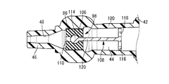
次に、図9,10には、本発明に係る医療用弁の第二の実施形態である弁機構98を備えた、雌コネクタ組立体が示されている。かかる雌コネクタ組立体では、流体通路を構成する筒状の翼付き雌コネクタ100に対して、弁機構98が収容装着されている。なお、以下の説明において、第一の実施形態と実質的に同一の部材乃至部位については、図中に第一の実施形態と同一の符号を付すことにより、説明を省略する。
Next, FIGS. 9 and 10 show a female connector assembly including a
雌コネクタ100は、第一の実施形態の外針ハブ18と略同じ構造とされており、内部に収容部44を有している。なお、雌コネクタ100の先端側(図10中、左端側)の開口部は、例えば管体102に挿し込まれて連結されて使用される。この管体102は、例えばカテーテル等に接続され得る。また、雌コネクタ100の基端側の開口部には、例えば第一実施形態と同様な構造の雄コネクタ88等が接続される。
The
また、雌コネクタ100の収容部44には、弁機構98が装着されている。弁機構98は、弁本体としてのゴム弁106と、ゴム弁106に嵌め込まれて組み付けられた作用部材としての押し子108によって構成されている。
In addition, a
ゴム弁106は、厚肉の円筒形状とされており、中心軸上には作用孔としての連通孔110が貫通形成されている。連通孔110は、円形断面で直線的に延びており、その軸方向中間部分が軸方向両端部分より大径とされて係止凹所112が形成されている。
The
そして、ゴム弁106は、雌コネクタ100の内孔に嵌め込まれており、ゴム弁106の外周面が雌コネクタ100の内周面に対して、密着されている。なお、ゴム弁106の外周面は、雌コネクタ100に接着されていても良い。
The
押し子108は、ロッド形状の連結部120を備えており、この連結部120の基端部(図9,10中の右側端部)に押圧部116が一体形成されていると共に、反対側の先端部に栓部114が一体形成されている。連結部120は、ゴム弁106の連通孔110の内径よりも小さい外径寸法で直線的に延びている。栓部114は、ゴム弁106の係止凹所112の内径寸法よりも大きな外径寸法の球形状を有している。押圧部116は、略円板形状を有しており、連結部120の軸直角方向に広がっている。また、押圧部116には、板厚方向に貫通する複数の透孔118が形成されている。
The
かかる押し子108は、ゴム弁106の連通孔110に対して、栓部114側から軸方向に挿し入れられて組み付けられている。そして、図9に示されているように、押し子108の栓部114が係止凹所112内に位置した状態で、連通孔110の内壁面に栓部114が押し付けられ、ゴム弁106に対して外周側への嵌合外力が及ぼされてゴム弁106が栓部114と雌コネクタ100の筒壁部との間で径方向に圧縮される。その結果、連通孔110が遮断状態に保持されて、雌コネクタ100の内孔が弁機構98によって閉鎖状態に維持される。
The
また、弁機構98が閉鎖状態とされた雌コネクタ100は、その基端側の開口部に雄コネクタ88を装着することにより、第一の実施形態と同様に、弁機構98が連通状態に切り換えられる。そして、雄コネクタ88内が、雌コネクタ100の収容部44と連通孔110を通じて、管体102の内孔に連通されるようになっている。
Further, in the
すなわち、雌コネクタ100に雄コネクタ88を装着すると、図10に示されているように、雄コネクタ88の先端部に突設されたチップ90が雌コネクタ100内に挿し入れられて、押し子108の押圧部116の外面がチップ90で押される。これにより、押し子108の全体が、雌コネクタ100の収容部44内で軸方向先端側に向かって押し込まれて変位する。それに伴って、栓部114が、ゴム弁106の連通孔110から先端側に抜け出す。その結果、連通孔110内には、連結部120が位置せしめられて、連結部120の外周面と連通孔110の内周面との間に、ゴム弁106の全長に亘って連続して延びる円筒形状の連通隙間が生ぜしめられる。この連通隙間によって、連通孔110が連通状態とされて、雌コネクタ100内の流体流路としての収容部44が連通状態に保持される。
That is, when the
なお、雌コネクタ100の収容部44の内周面は、押し子108の押圧部116が変位する領域において軸方向で先端側(図10中の左側)に向かって次第に小径となるテーパ面とされている。そして、押圧部116が収容部44内で軸方向先端側へ所定量だけ変位した際、押圧部116の外周縁部が収容部44の内周面に当接するようになっている。かかる当接にて、押圧部116ひいては押し子108の収容部44内における軸方向前方への変位量が制限される。これにより、押し子108が、雌コネクタ100の収容部44内で必要以上に先端側に変位するのを防いで、雌コネクタ100の先端側開口部(貫通孔48)が、栓部114で蓋されることを防止している。
The inner peripheral surface of the
このような本実施形態の雌コネクタ組立体においても、前記第一の実施形態と同様に、流体通路を形成する連通孔110を栓部114で遮断した状態から押し子108を軸方向に移動させることで、連通孔110を速やかに連通状態とすることが出来る。しかも、連通孔110は、ゴム弁106に外力が及ぼされていない初期形状で連通状態とされていることから、かかる連通孔110ひいては流体通路の連通状態が高い信頼性をもって確実に発現され得る。
Also in the female connector assembly of this embodiment, the
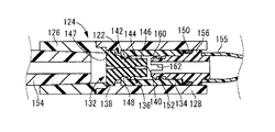
さらに、図11,12には、本発明に係る医療用弁の第三の実施形態である弁機構122を備えた、流路形成部材が示されている。本実施形態の流路形成部材は、流体通路を構成する筒状のハウジング124と、ハウジング124に収容状態で装着された弁機構122とを含んで構成されている。
Further, FIGS. 11 and 12 show a flow path forming member provided with a
ハウジング124は、それぞれ略円筒形状とされた第1筒部材126と第2筒部材128が、軸方向で連結された構造とされている。一方、弁機構122は、弁本体としてのゴム弁132と、作用部材としての押し子134を含んで構成されている。ゴム弁132は、弁部136と支持部138を一体的に備えている。
The
ゴム弁132における弁部136は、厚肉の略円筒形状を有しており、中心軸上に作用孔としての連通孔140が貫通形成されている。また、弁部136の軸方向中間部分の外周面には段差が設けられており、段差を挟んで一方の側(図11中、左側)が大径部142とされていると共に、他方の側が小径部144とされている。更に、弁部136には、大径部142側の端部においてフランジ状の支持部138が一体形成されている。また、小径部144の外周面には、軸方向中間部分を周方向に延びる突条146が一体形成されている。
The valve portion 136 of the
そして、このゴム弁132は、ハウジング124に嵌め入れられて、ハウジング124の軸方向略中央部分に収容状態で装着されている。かかる装着状態下、ゴム弁132は、弁部136が基端側(図11中、右側)に向けられている。また、先端側(図11中、左側)に位置する支持部138は、ハウジング124の内周面に形成された環状の位置決め凹溝147に対して外周縁部が嵌め込まれて密着状態で位置決めされている。
The
一方、押し子134は、略円筒形状を有しており、硬質材料で形成されている。また、押し子134の軸方向先端部(図11中、左側端部)には、内周面上に突出する環状の作用突部148が一体形成されている。この作用突部148の内径寸法は、ゴム弁132の大径部142の外径寸法よりも小さくされていると共に、小径部144の外径寸法と略同じとされている。更に、押し子134の軸方向中間部分には、内周面に突出する係止突起152が一体形成されている。
On the other hand, the pusher 134 has a substantially cylindrical shape and is formed of a hard material. Further, an
そして、押し子134の先端部開口からゴム弁132の弁部136が軸方向に差し入れられて、押し子134がゴム弁132に対して外挿状態で組み付けられている。また、図11に示されているように、押し子134の作用突部148が、弁部136の大径部142の外周面に嵌め合わされている。これにより、弁部136には、押し子134による内周側への締付外力が及ぼされており、弁部136の大径部142が縮径変形することで連通孔140が押し潰されて閉鎖されている。
The valve portion 136 of the
このような構造とされた流路形成部材は、例えば、第1筒部材126の開口部に対して、医療用チューブ154が接続されると共に、第2筒部材128の開口部に対して、医療用チューブ155が接続される。これにより、ハウジング124内には、ゴム弁132の連通孔140を含んで流体通路が形成され、かかる流体通路によって両側のチューブ154,155の相互連通路を形成することとなる。
In the flow path forming member having such a structure, for example, the
ここにおいて、第2筒部材128に接続されるチューブ155の接続端部には、コネクタ156が取り付けられている。コネクタ156は、略円筒形状を有しており、樹脂等の硬質材で形成されている。そして、チューブ155がハウジング124に接続されると共に、コネクタ156が、ハウジング124に収容された押し子134に対して、基端側(図11中、右端側)の開口部から差し入れられている。更に、コネクタ156には、押し子134に差し入れられる先端部において外周面に突出する係止爪部160が一体形成されている。この係止爪部160が押し子134の係止突起152に係止されることにより、コネクタ156の押し子134からの抜け出しが阻止されるようになっている。なお、コネクタ156の先端部には、軸方向に切れ込むスリット162が形成されており、押し子134への差し入れ作業が容易とされている。また、コネクタ156には、ハウジング124に差し入れられる中間部分に、ゴムリング150が外嵌装着されており、コネクタ156とハウジング124が流体密に組み付けられている。
Here, a
そして、ハウジング124に連結されたコネクタ156に対して軸方向の外力を加えて、コネクタ156をハウジング124から軸方向外方に抜き出す方向に変位させることにより、図12に示されているように、弁機構122の閉鎖状態を解除して連通孔140を含む流体通路を連通状態に切り換えることが出来るようになっている。即ち、コネクタ156をハウジング124に対して軸方向外方に変位させることにより、コネクタ156と係合された押し子134が、ゴム弁132に対して軸方向で相対変位させられる。その結果、ゴム弁132の弁部136の大径部142に外嵌された押し子134の作用突部148が、弁部136の小径部144上に移動して、ゴム弁132の大径部142への外力作用が解除される。これにより、弁部136に形成された連通孔140を連通させて、ハウジング124の内孔を連通状態に切り換えることが出来るのである。
Then, by applying an external force in the axial direction to the
従って、本実施形態の弁機構122を備えた流路筒部材においても、押し子134を軸方向に変位操作することにより、前記第一及び第二の実施形態と同様に流体通路を形成する連通孔140を速やかに連通状態とすることが出来る。しかも、連通孔140は、ゴム弁132に外力が及ぼされていない初期形状で連通状態とされていることから、かかる連通孔140ひいては流体通路の連通状態が高い信頼性をもって確実に発現され得る。
Therefore, also in the flow path cylinder member provided with the
加えて、本実施形態においては、ハウジング124にチューブ154,155を接続して流体通路を形成する操作から独立して、弁機構122における遮断状態と連通状態の切り換えを行うことが出来る。それ故、例えば、予め流体通路を形成して遮断状態に保持した後、自由なタイミングで輸液や採血を開始することも可能となる。
In addition, in the present embodiment, the shutoff state and the communication state of the
しかも、本実施形態の弁機構122は、図12に示された連通状態において、コネクタ156をハウジング124に対し軸方向に押し込む方向に操作することにより、押し子134を弁部136に対して軸方向で相対変位させることも出来る。そして、かかるコネクタ156の押込操作により、押し子134の作用突部148を、ゴム弁132の小径部144から大径部142に変位させて、図11に示されているように、連通孔140を再び遮断状態とすることが可能となる。
In addition, the
以上、本発明の幾つかの実施形態について説明してきたが、これらはあくまでも例示であって、本発明は、かかる実施形態の具体的な記載によって、限定的に解釈されるものではない。 As mentioned above, although several embodiment of this invention has been described, these are illustrations to the last, and this invention is not limitedly interpreted by the specific description of this embodiment.
例えば、前記第一〜第三の実施形態では、弁本体が何れもゴム弾性体単体で形成されているが、図13に示された弁本体としての止血弁164のように、複合構造としても良い。かかる止血弁164は、支持部60に対して硬質の規制部材166が固着されている。この規制部材166で支持部60の変形が抑えられることにより、例えば図2に示されている如き外針ハブ18内への装着状態下、支持部60を外針ハブ18に対して一層強固に位置決めすることが可能となる。
For example, in the first to third embodiments, the valve main body is formed of a single rubber elastic body. However, like the
また、前記第一〜第三の実施形態では、弁本体の径方向中央部を貫通するように連通孔70,110,140が一つ形成されていたが、例えば、図14に示された弁本体としての止血弁168のように、軸方向に貫通する連通孔170が、複数形成されていても良い。なお、複数の連通孔170を形成するに際しては、図14に示されているように、止血弁168の中心軸を外れた位置に全ての連通孔170を形成しても良いし、一つの連通孔を中心軸上に位置させても良い。また、複数の連通孔170のうちの幾つかを異なる内径寸法で形成しても良い。
In the first to third embodiments, one
さらに、弁本体に形成される作用孔の形状は、特に限定されるものではなく、例えば、断面形状を楕円形や矩形にしても良い。また、弁本体に形成される作用孔は、軸方向に略一定の断面形状で形成されていても良いし、断面積や断面形状が軸方向で変化していても良い。 Furthermore, the shape of the working hole formed in the valve body is not particularly limited. For example, the cross-sectional shape may be an ellipse or a rectangle. Further, the working hole formed in the valve body may be formed with a substantially constant cross-sectional shape in the axial direction, or the cross-sectional area or the cross-sectional shape may be changed in the axial direction.
また、前記第一〜第三の実施形態では、何れも、作用孔(連通孔)によって、流体通路を連通状態とする連通路が構成されているが、例えば、弁本体の外周面と、流体通路を構成する部材(外針ハブ18や雌コネクタ100,ハウジング124等)の内周面との間に隙間が形成されて、かかる隙間により連通路が形成されていても良い。このような構造では、例えば、弁本体に貫通形成された作用孔に作用部材(押し子)を押し込んで、弁本体の外径寸法を拡径させることにより、弁本体の外周面上に形成された隙間を消失させて流体通路を遮断させることが出来る。
In each of the first to third embodiments, the communication passage is configured by the working hole (communication hole) to communicate the fluid passage. For example, the outer peripheral surface of the valve body and the fluid A gap may be formed between the members constituting the passage (the
かかる態様の具体例を、図15〜16に示す。図示された弁本体172は、厚肉の円環板形状を有している。この弁本体は、流体通路を形成する円筒形状の通路ハウジング174内に収容されている。ハウジング174の軸方向中間部分には、内周面に開口する環状凹溝176が形成されており、この環状凹溝176に外周部分が入り込んだ状態で、弁本体172が装着されている。また、弁本体172の中心軸上に作用孔178が貫通形成されており、この作用孔178に対して、作用部材としての作用ロッド180が挿通状態で組み付けられている。作用ロッド180は、一定の円形断面でストレートに延びる軸部182の先端部分に大径円形断面の頭部184が設けられている。この軸部182の外径寸法が弁本体172の作用孔の内径寸法と略同じとされている。一方、頭部184は、弁本体172の作用孔178内に位置せしめられることにより、作用孔178ひいては弁本体172を拡径方向に弾性変形させるようになっている。そして、作用ロッド180を弁本体172に対して軸方向で相対変位させることで、通路ハウジング174内に形成される流体通路を遮断状態と連通状態に切り換えることが出来る。即ち、作用ロッド180の頭部184を弁本体172の作用孔178内に位置せしめた、図15(a)の状態下では、頭部184の外周面が作用孔178の内周面に密着して作用孔178が拡径され、弁本体172が弾性変形することで大径化して弁本体172の外周面が通路ハウジング174の環状凹溝176の内周面に密着することで、通路ハウジング174内の流体通路が遮断状態に維持される。一方、かかる状態から作用ロッド180が軸方向に変位させられて、軸部182が作用孔178内に位置すると、弁本体172は外力が及ぼされていない略初期形状に戻り、弁本体172の外径寸法が縮小することで、弁本体172の外周面と通路ハウジング174の内周面との間には連通路186が形成される。この連通路186の出現により、通路ハウジング174内の流体通路が連通状態とされる。なお、図15中、188は、環状凹溝176の軸方向両側壁面において周上の複数箇所に突設された支持突起であり、これら複数の支持突起188で弁本体172が軸方向両側から位置決め支持されている。本実施形態において、支持突起188は通路ハウジング174と一体形成されているが、例えば、別体形成された支持突起を通路ハウジングに対して接着等によって後付けで取り付けることも出来る。
Specific examples of this aspect are shown in FIGS. The illustrated
なお、図15,16に示された態様では、流体通路の連通状態下、作用孔178が作用ロッド180によって遮断されているが、作用ロッド180の外径を、周上の少なくとも一部において作用孔178よりも小径とする等して、弁本体172の内孔と外周面上の両方に、流体通路を連通状態とする通路(作用孔178と連通路186)が形成されるようになっていても良い。
In the mode shown in FIGS. 15 and 16, the working
また、図17に示されているように、弁本体190に対して、押し子192を外挿させて、弁本体190に対して径方向内方に向かう嵌合外力を及ぼすことにより流体通路を遮断すると共に、嵌合外力を解除することにより、弁本体190の外周面上に連通路を形成して、流体通路を連通状態に切り替える構造を採用することも出来る。より具体的には、弁本体190は、先端側(図17中、左)が小径部62、基端側が大径部64とされた段付円筒形状を有していると共に、その先端側端部には、外フランジ状の支持部60が一体形成されている。この支持部60には、小径部62を外れた部位において軸方向に貫通する挿通孔194が形成されている。また、弁本体190に外挿される押し子192は、弁本体190の大径部64よりも大径の略円筒形状を有しており、先端側の端部には、弁本体190の小径部62よりも大径且つ大径部64よりも小径の内径を有する作用突部82が一体形成されている。それら弁本体190と押し子192は、ハウジング124の内孔に収容配置されている。そして、図17(a)に示されているように、押し子192の作用突部82が弁本体190の大径部64上に位置せしめられることにより、作用突部82の先端面(内周面)が、弁本体190の大径部64の外周面に対して押し付けられる。これにより、ハウジング124の内孔で構成された流体通路が、弁本体190と押し子192の協働によって遮断される。なお、押し子192の外周面とハウジング124の内周面との隙間は、ゴムリング150によって流体密に遮断されている。また、図17(b)に示されているように、押し子192が先端側に向かって軸方向に押し込まれて変位せしめられることにより、押し子192の作用突部82が、弁本体190の小径部62上に位置せしめられる。そして、作用突部82の先端面と、弁本体190の小径部62の外周面との隙間によって連通路が形成されて、流体通路が該連通路と支持部60に形成された挿通孔194とを通じて連通状態とされる。
Further, as shown in FIG. 17, the
さらに、前記第三の実施形態において、コネクタ156をハウジング124に対して軸方向外方に向かって付勢するコイルスプリング等の付勢手段を設けても良い。このような付勢手段を設ければ、コネクタ156をハウジング124に対して付勢手段の付勢力に抗して押し込むだけで、その後、付勢手段の付勢力によって自動的にコネクタ156をハウジング124から引き抜く方向に軸方向変位させて、流体通路を連通状態とすることが出来る。また、かかる付勢手段の付勢力は、コネクタ156をハウジング124からの引き抜き方向端に位置保持し得ることから、流体通路の連通状態への保持が一層安定して実現可能となる。
Further, in the third embodiment, a biasing means such as a coil spring that biases the
その他、一々列挙はしないが、本発明は、当業者の知識に基づいて種々なる変更,修正,改良等を加えた態様において実施され得るものであり、また、そのような実施態様が、本発明の趣旨を逸脱しない限り、何れも、本発明の範囲内に含まれるものであることは、言うまでもない。 In addition, although not enumerated one by one, the present invention can be carried out in a mode to which various changes, modifications, improvements and the like are added based on the knowledge of those skilled in the art. It goes without saying that all are included in the scope of the present invention without departing from the spirit of the present invention.
10,98,122:弁機構、18:外針ハブ、54,164,168:止血弁、56,108,134:押し子、70,110,140,170:連通孔、74:狭窄部、100:雌コネクタ、106,132:ゴム弁、124:ハウジング
10, 98, 122: valve mechanism, 18: outer needle hub, 54, 164, 168: hemostasis valve, 56, 108, 134: pusher, 70, 110, 140, 170: communication hole, 74: constriction, 100 :
Claims (7)
前記流体通路に配設される弾性体からなる弁本体を備えていると共に、該弁本体には該流体通路の通路長方向となる軸方向に貫通する作用孔が形成されており、該弁本体の該流体通路への配設状態下で該作用孔と該弁本体の外周面上との少なくとも一方によって該流体通路を連通状態とする連通路が形成されるようになっている一方、該弁本体における該作用孔への内挿と該外周面への外挿との何れかによって組み付けられて、該弁本体に対して外周側又は内周側への嵌合外力を及ぼすことにより、該連通路を消失させて該流体通路を遮断状態に保持すると共に、該弁本体に対して軸方向で相対変位させられることによって該弁本体に対する嵌合外力を解除して該流体通路を連通状態とする作用部材を設けたことを特徴とする医療用弁。 A medical valve that is attached to a fluid passage provided in a medical instrument or device and switches the fluid passage between a communication state and a cutoff state,
The valve main body is provided with an elastic body disposed in the fluid passage, and the valve main body is formed with an action hole penetrating in an axial direction which is a passage length direction of the fluid passage. In the state where the fluid passage is disposed in the fluid passage, at least one of the working hole and the outer peripheral surface of the valve body forms a communication passage that makes the fluid passage communicate with the valve. It is assembled by either insertion into the working hole in the main body or extrapolation into the outer peripheral surface, and exerts a fitting external force on the outer peripheral side or inner peripheral side with respect to the valve main body, thereby The passage is eliminated and the fluid passage is held in a shut-off state, and the fluid passage is brought into a communication state by releasing a fitting external force to the valve body by being displaced relative to the valve body in the axial direction. A medical valve comprising an action member.
Priority Applications (1)
| Application Number | Priority Date | Filing Date | Title |
|---|---|---|---|
| JP2008321179A JP2010142363A (en) | 2008-12-17 | 2008-12-17 | Medical valve |
Applications Claiming Priority (1)
| Application Number | Priority Date | Filing Date | Title |
|---|---|---|---|
| JP2008321179A JP2010142363A (en) | 2008-12-17 | 2008-12-17 | Medical valve |
Publications (1)
| Publication Number | Publication Date |
|---|---|
| JP2010142363A true JP2010142363A (en) | 2010-07-01 |
Family
ID=42563417
Family Applications (1)
| Application Number | Title | Priority Date | Filing Date |
|---|---|---|---|
| JP2008321179A Pending JP2010142363A (en) | 2008-12-17 | 2008-12-17 | Medical valve |
Country Status (1)
| Country | Link |
|---|---|
| JP (1) | JP2010142363A (en) |
Cited By (7)
| Publication number | Priority date | Publication date | Assignee | Title |
|---|---|---|---|---|
| JP2012130523A (en) * | 2010-12-22 | 2012-07-12 | Nipro Corp | Indwelling needle assembly |
| WO2015141365A1 (en) * | 2014-03-20 | 2015-09-24 | テルモ株式会社 | Catheter assembly |
| WO2015141366A1 (en) * | 2014-03-20 | 2015-09-24 | テルモ株式会社 | Catheter assembly |
| CN108175498A (en) * | 2018-01-31 | 2018-06-19 | 海口市人民医院(中南大学湘雅医学院附属海口医院) | Cooling device of microwave ablation needle |
| WO2021182366A1 (en) * | 2020-03-09 | 2021-09-16 | テルモ株式会社 | Indwelling catheter, medical valve, and catheter assembly |
| CN115282461A (en) * | 2016-08-04 | 2022-11-04 | 尼普洛株式会社 | Needle assembly with valve and indwelling needle assembly |
| JP2023000347A (en) * | 2021-06-17 | 2023-01-04 | 朝日インテック株式会社 | Medical valve and opening/closing device for medical valve |
Citations (2)
| Publication number | Priority date | Publication date | Assignee | Title |
|---|---|---|---|---|
| JPS5576659A (en) * | 1978-10-17 | 1980-06-09 | Viggo Ab | Catheter assembled body |
| JP2001506156A (en) * | 1996-12-16 | 2001-05-15 | アイシーユー メディカル、インコーポレイテッド | Positive flow valve |
-
2008
- 2008-12-17 JP JP2008321179A patent/JP2010142363A/en active Pending
Patent Citations (2)
| Publication number | Priority date | Publication date | Assignee | Title |
|---|---|---|---|---|
| JPS5576659A (en) * | 1978-10-17 | 1980-06-09 | Viggo Ab | Catheter assembled body |
| JP2001506156A (en) * | 1996-12-16 | 2001-05-15 | アイシーユー メディカル、インコーポレイテッド | Positive flow valve |
Cited By (13)
| Publication number | Priority date | Publication date | Assignee | Title |
|---|---|---|---|---|
| JP2012130523A (en) * | 2010-12-22 | 2012-07-12 | Nipro Corp | Indwelling needle assembly |
| WO2015141365A1 (en) * | 2014-03-20 | 2015-09-24 | テルモ株式会社 | Catheter assembly |
| WO2015141366A1 (en) * | 2014-03-20 | 2015-09-24 | テルモ株式会社 | Catheter assembly |
| JPWO2015141366A1 (en) * | 2014-03-20 | 2017-04-06 | テルモ株式会社 | Catheter assembly |
| JPWO2015141365A1 (en) * | 2014-03-20 | 2017-04-06 | テルモ株式会社 | Catheter assembly |
| CN115282461A (en) * | 2016-08-04 | 2022-11-04 | 尼普洛株式会社 | Needle assembly with valve and indwelling needle assembly |
| CN108175498A (en) * | 2018-01-31 | 2018-06-19 | 海口市人民医院(中南大学湘雅医学院附属海口医院) | Cooling device of microwave ablation needle |
| CN108175498B (en) * | 2018-01-31 | 2024-02-02 | 海口市人民医院(中南大学湘雅医学院附属海口医院) | Cooling device of microwave ablation needle |
| WO2021182366A1 (en) * | 2020-03-09 | 2021-09-16 | テルモ株式会社 | Indwelling catheter, medical valve, and catheter assembly |
| JPWO2021182366A1 (en) * | 2020-03-09 | 2021-09-16 | ||
| JP7481429B2 (en) | 2020-03-09 | 2024-05-10 | テルモ株式会社 | Indwelling catheter, medical valve and catheter assembly |
| JP2023000347A (en) * | 2021-06-17 | 2023-01-04 | 朝日インテック株式会社 | Medical valve and opening/closing device for medical valve |
| JP7690330B2 (en) | 2021-06-17 | 2025-06-10 | 朝日インテック株式会社 | Medical valves and medical valve opening and closing devices |
Similar Documents
| Publication | Publication Date | Title |
|---|---|---|
| US7396348B2 (en) | Medical valve with expandable member | |
| CN109562253B (en) | Needle assembly with valve and indwelling needle assembly | |
| KR102638670B1 (en) | Catheter devices with valves and related methods | |
| US11839752B2 (en) | Hemostasis valve-equipped indwelling needle and indwelling needle assembly | |
| US5921264A (en) | Swabbable needleless valve | |
| JP2006102255A (en) | Infusion line connection structure and connector having the connection structure | |
| JP5054989B2 (en) | Liquid infusion tool | |
| JP2014528807A (en) | Stretch non-penetrating blood control valve that can be used in various ways | |
| US20080208132A1 (en) | Indwelling Needle | |
| JP2006102254A (en) | Infusion line connection structure and connector having the connection structure | |
| CN105148376A (en) | Catheter assembly with seal member | |
| JP2002263197A (en) | Indwelling catheter | |
| JP4611757B2 (en) | Infusion line connection device | |
| WO2013115221A1 (en) | Connector | |
| JP6735024B2 (en) | Indwelling needle | |
| WO2022163311A1 (en) | Medical connector | |
| JP5578488B2 (en) | Indwelling needle assembly | |
| JP2013154066A (en) | Connector | |
| JP2023080198A (en) | Needle assembly with valve | |
| JP2004195016A (en) | Coupling device | |
| US20090069757A1 (en) | Elastomeric seal for use within a catheter component | |
| JP4157349B2 (en) | Fitting device | |
| US10512767B2 (en) | Hemostatic connector | |
| CN119816340A (en) | Catheter device with valve and related methods | |
| AU2002356132A1 (en) | Medical valve with expandable seal member |
Legal Events
| Date | Code | Title | Description |
|---|---|---|---|
| A621 | Written request for application examination |
Free format text: JAPANESE INTERMEDIATE CODE: A621 Effective date: 20111128 |
|
| A977 | Report on retrieval |
Free format text: JAPANESE INTERMEDIATE CODE: A971007 Effective date: 20130307 |
|
| A131 | Notification of reasons for refusal |
Free format text: JAPANESE INTERMEDIATE CODE: A131 Effective date: 20130311 |
|
| A02 | Decision of refusal |
Free format text: JAPANESE INTERMEDIATE CODE: A02 Effective date: 20130702 |