JP2010142494A - Relaxation apparatus - Google Patents
Relaxation apparatus Download PDFInfo
- Publication number
- JP2010142494A JP2010142494A JP2008324597A JP2008324597A JP2010142494A JP 2010142494 A JP2010142494 A JP 2010142494A JP 2008324597 A JP2008324597 A JP 2008324597A JP 2008324597 A JP2008324597 A JP 2008324597A JP 2010142494 A JP2010142494 A JP 2010142494A
- Authority
- JP
- Japan
- Prior art keywords
- body support
- drive
- swing
- transmission mechanism
- base
- Prior art date
- Legal status (The legal status is an assumption and is not a legal conclusion. Google has not performed a legal analysis and makes no representation as to the accuracy of the status listed.)
- Withdrawn
Links
Images


Classifications
-
- A—HUMAN NECESSITIES
- A47—FURNITURE; DOMESTIC ARTICLES OR APPLIANCES; COFFEE MILLS; SPICE MILLS; SUCTION CLEANERS IN GENERAL
- A47C—CHAIRS; SOFAS; BEDS
- A47C3/00—Chairs characterised by structural features; Chairs or stools with rotatable or vertically-adjustable seats
- A47C3/02—Rocking chairs
- A47C3/025—Rocking chairs with seat, or seat and back-rest unit, elastically mounted in a rigid frame
- A47C3/0255—Rocking chairs with seat, or seat and back-rest unit, elastically mounted in a rigid frame pivotally mounted in the base frame, e.g. swings
-
- A—HUMAN NECESSITIES
- A47—FURNITURE; DOMESTIC ARTICLES OR APPLIANCES; COFFEE MILLS; SPICE MILLS; SUCTION CLEANERS IN GENERAL
- A47C—CHAIRS; SOFAS; BEDS
- A47C3/00—Chairs characterised by structural features; Chairs or stools with rotatable or vertically-adjustable seats
- A47C3/02—Rocking chairs
- A47C3/025—Rocking chairs with seat, or seat and back-rest unit, elastically mounted in a rigid frame
- A47C3/0251—Rocking chairs with seat, or seat and back-rest unit, elastically mounted in a rigid frame driven by electric motors
Landscapes
- Rehabilitation Tools (AREA)
- Chairs Characterized By Structure (AREA)
Abstract
【課題】リラックス装置搬送時における搬送の容易性を向上させることができるリラックス装置を提供する。
【解決手段】揺動駆動装置12は、揺動動作の駆動力を発生させる駆動部としてのモータ20と、そのモータ20からの駆動力を伝達させる駆動力伝達機構21とを有してリラックス装置の基台11に備えられる。そして、駆動力伝達機構21は、減速機23を構成するウォーム軸23aとウォームホイール23bとを有し、それらのねじ溝が進み角4度以下となるように構成され、身体支持部材側からモータ20側への作動力に対してセルフロックがかかるように構成される。
【選択図】図3The present invention provides a relax device capable of improving the ease of transport during the transport of the relax device.
A swing drive device includes a motor as a drive unit that generates a drive force for a swing operation, and a drive force transmission mechanism that transmits a drive force from the motor. The base 11 is provided. The driving force transmission mechanism 21 includes a worm shaft 23a and a worm wheel 23b that constitute the speed reducer 23, and is configured such that their thread grooves have an advance angle of 4 degrees or less. It is configured to be self-locked against the operating force toward the 20 side.
[Selection] Figure 3
Description
本発明は、使用者にリラックス効果を付与するリラックス装置に関するものである。 The present invention relates to a relaxation device that imparts a relaxation effect to a user.
従来、使用者にリラックス効果を付与するリラックス装置として例えば特許文献1に開示されており、このリラックス装置は使用者の身体を着座状態若しくは寝た状態で支持する身体支持手段を揺動駆動手段にて緩やかに揺動させて、使用者にリラックス効果を付与するものである。
ところで、上記リラックス装置では、身体支持手段を揺動可能に構成しているため、例えば身体支持手段を構成する背もたれ部とオットマンとを搬送者2人で持ってリラックス装置を搬送する際に、その搬送者にて保持する身体支持手段に対して揺動駆動手段を有する基台側が揺動してしまって搬送し難く、その改善が望まれている。 By the way, in the said relaxation apparatus, since the body support means is comprised so that rocking is possible, for example, when carrying a relax apparatus with the backrest part and ottoman which comprise a body support means, and two carriers, The base side having the swinging drive means swings with respect to the body support means held by the transporter and is difficult to transport, and an improvement thereof is desired.
本発明は、上記課題を解決するためになされたものであって、その目的は、リラックス装置搬送時における搬送の容易性を向上させることができるリラックス装置を提供することにある。 The present invention has been made to solve the above-described problems, and an object of the present invention is to provide a relax device that can improve the ease of transport during the transport of the relax device.
上記課題を解決するために、請求項1に記載の発明は、使用者の身体を支持する身体支持手段と、該身体支持手段を前後方向に揺動動作させる揺動駆動手段と、該揺動駆動手段を制御してリラックス揺動を行う制御手段とを備えたリラックス装置であって、前記揺動駆動手段は、前記揺動動作の駆動力を発生させる駆動部と、該駆動部からの駆動力を伝達させる駆動力伝達機構とを有して前記リラックス装置の基台に備えられるものであり、前記駆動力伝達機構は、前記身体支持手段側から前記駆動部側への作動力に対してセルフロックがかかるように構成されたことをその要旨とする。
In order to solve the above-mentioned problem, the invention described in
この発明では、揺動駆動手段は、揺動動作の駆動力を発生させる駆動部と、その駆動部からの駆動力を伝達させる駆動力伝達機構とを有してリラックス装置の基台に備えられるものであり、駆動力伝達機構は、身体支持手段側から駆動部側への作動力に対してセルフロックがかかるように構成される。これにより、身体支持手段を持って本装置を搬送する際に、身体支持手段に対して揺動駆動手段を有する基台側が揺動してしまうことを防止することができるため、搬送時おける搬送の容易性を向上させることができる。 In this invention, the swing drive means has a drive unit that generates a drive force for the swing operation and a drive force transmission mechanism that transmits the drive force from the drive unit, and is provided on the base of the relax device. The driving force transmission mechanism is configured to be self-locked against the operating force from the body support means side to the driving unit side. Thereby, when the apparatus is transported with the body support means, it is possible to prevent the base side having the swing drive means from swinging with respect to the body support means, so that the transport during the transport is possible. Can be improved.
請求項2に記載の発明は、請求項1に記載のリラックス装置において、前記駆動力伝達機構は、ウォーム軸とウォームホイールとを有し、前記ウォームホイール及び前記ウォーム軸の進み角が4度以下となるように構成されたことをその要旨とする。 According to a second aspect of the present invention, in the relax device according to the first aspect, the driving force transmission mechanism has a worm shaft and a worm wheel, and the advance angle of the worm wheel and the worm shaft is 4 degrees or less. The gist is that it is configured as follows.
この発明では、駆動力伝達機構は、ウォーム軸とウォームホイールとを有している。そして、駆動力伝達機構を構成するウォームホイール及びウォーム軸の進み角が4度以下となるように構成される。これにより、駆動力伝達機構にてセルフロックを実現できるため、身体支持手段を持って本装置を搬送する際に、身体支持手段に対して揺動駆動手段を有する基台側が揺動してしまうことを防止することができるため、搬送時おける搬送の容易性を向上させることができる。 In this invention, the driving force transmission mechanism has a worm shaft and a worm wheel. And it is comprised so that the advance angle of the worm wheel and worm shaft which comprises a driving force transmission mechanism may be 4 degrees or less. As a result, self-locking can be realized by the driving force transmission mechanism, so that when the apparatus is transported with the body support means, the base side having the swing drive means swings relative to the body support means. Since this can be prevented, the ease of transport during transport can be improved.
請求項3に記載の発明は、請求項1又は2に記載のリラックス装置において、前記身体支持手段には、その幅方向へ揺れ動く場合に、その動きを規制する規制手段が設けられたことをその要旨とする。 According to a third aspect of the present invention, in the relaxing device according to the first or second aspect, the body supporting means is provided with a regulating means for regulating the movement when the body supporting means swings in the width direction. The gist.
この発明では、身体支持手段には、その幅方向へ揺れ動く場合に、その動きを規制する規制手段が設けられるため、本装置搬送時に身体支持手段に対して揺動駆動手段を有する基台側が幅方向に揺れることが規制される。これにより、本装置搬送時における搬送の容易性をより向上させることができる。 In the present invention, since the body support means is provided with the restriction means for restricting the movement when swinging in the width direction, the width of the base side having the rocking drive means with respect to the body support means when the apparatus is transported is wide. Shaking in the direction is restricted. Thereby, the ease of conveyance at the time of this apparatus conveyance can be improved more.
請求項4に記載の発明は、請求項3に記載のリラックス装置において、前記規制手段は、前記身体支持手段を揺動可能に支持する揺動部材と前記基台とで構成され、その2部材間の接触にて規制することをその要旨とする。 According to a fourth aspect of the present invention, in the relax device according to the third aspect, the restricting means includes a swing member that supports the body support means so as to be swingable and the base, and the two members. The gist is to regulate by contact between.
この発明では、規制手段は、身体支持手段を揺動可能に支持する揺動部材と基台とで構成される。そして、規制手段はその2部材間の接触にて規制するよう構成される。つまり、規制手段がリラックス装置を構成する2部材間の接触にて規制するよう構成されるため、別途規制手段を設ける必要がなく、部材点数の増加を抑えることができる。 In the present invention, the restricting means comprises a swing member and a base that support the body support means so as to be swingable. And a control means is comprised so that it may control by the contact between the two members. That is, since the restricting means is configured to restrict by contact between two members constituting the relax device, it is not necessary to provide a separate restricting means, and an increase in the number of members can be suppressed.
請求項5に記載の発明は、請求項3又は4に記載のリラックス装置において、前記規制手段は、2部材間の接触にてその規制がなされるものであり、少なくとも一方の接触部位に弾性部材が設けられることをその要旨とする。 According to a fifth aspect of the present invention, in the relax device according to the third or fourth aspect, the regulating means is regulated by contact between two members, and an elastic member is provided at at least one contact portion. The gist of this is to be provided.
この発明では、規制手段は、2部材間の接触にてその規制がなされるものであり、少なくとも一方の接触部位に弾性部材が設けられる。そのため、弾性部材にて2部材間の接触時の接触音(異音)の発生を抑制することができる。 In the present invention, the regulating means is regulated by contact between two members, and an elastic member is provided at at least one contact portion. Therefore, generation | occurrence | production of the contact sound (abnormal noise) at the time of the contact between two members can be suppressed with an elastic member.
本発明によれば、リラックス装置搬送時における搬送の容易性を向上させることができるリラックス装置を提供することができる。 ADVANTAGE OF THE INVENTION According to this invention, the relaxation apparatus which can improve the ease of conveyance at the time of relaxation apparatus conveyance can be provided.
以下、本発明を具体化した一実施形態を図面に従って説明する。
図1は、本実施形態のリラックス装置の概略構成図を示す。図1に示すように、リラックス装置10は、その基台11の底部11aが図示しない床面に載置されるとともに、基台11に設けられた揺動駆動手段としての揺動駆動装置12と該揺動駆動装置12により揺動される身体支持手段としての身体支持部材13とを備えている。
DESCRIPTION OF EXEMPLARY EMBODIMENTS Hereinafter, an embodiment of the invention will be described with reference to the drawings.
FIG. 1 is a schematic configuration diagram of a relaxation device according to the present embodiment. As shown in FIG. 1, the
揺動駆動装置12は、駆動部としてのモータ20と、駆動力伝達機構21とから構成されている。
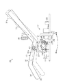
モータ20は、揺動動作の駆動力を発生させるものであり、基台11の底部11a上面に設けられるとともに、前記底部11a上面に設けられる制御手段としての制御部22によりその駆動が制御されている。また、図3に示すように、モータ20の回転軸20aの先端側には、駆動力伝達機構21を構成するプーリ21aが回転軸20aと一体回転可能に取り付けられている。また、そのプーリ21aと、減速機23側のプーリ21bとには、駆動ベルト21cが掛け渡されており、その駆動ベルト21cによってモータ20の回転軸20aの回転力(駆動力)が減速機23側に伝達されるようになっている。
The
The
減速機23側のプーリ21bは、減速機23を構成するとともに2つの軸受24によって回転可能に支持されるウォーム軸23aと一体回転可能に取り付けられている。減速機23を構成するウォーム軸23aは、ウォームホイール23bと噛合されており、ウォーム軸23a及びウォームホイール23bのねじ溝(図示略)は進み角4度以下となるように形成されている。ウォームホイール23bの径方向中心位置には、出力軸25が一体回転可能に設けられている。その出力軸25には、減速機23の回転駆動を半径の極めて大きな円弧運動に変換するクランク機構26を構成するクランク部材26aの基端が一体回転可能に取り付けられており、クランク部材26aの先端がロッド部材26bの基端と回転可能に接続されている。ロッド部材26bの先端は、図1に示すように身体支持部材13が固定される四角枠状のベース部27の下部と接続されている。
The pulley 21b on the side of the
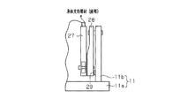
前記基台11には、その底部11aから上方向に突設される支持枠11bが備えられており、揺動部材としての2つのリンク部材28はそれらの基端が各支持枠11b上部に所定間隔を有して回転可能に連結されるとともに、各先端がベース部27の下部と回転可能に連結されている。つまり、この2本のリンク部材28は、基端を中心として回動するようになっており、クランク機構26からの駆動力を基に、ベース部27に固定される身体支持部材13をロッキングチェア等のように前後方向に揺動させている。また、図4に示すように前記リンク部材28は、例えば、本装置10の揺動動作停止位置において身体支持部材13が揺動駆動装置12を有する基台11に対して幅方向に相対的に移動した場合、規制手段を構成する支持枠11bと当接するようになっている。尚、支持枠11bには、その支持枠11bとリンク部材28との接触部位に弾性部材29が設けられている。
The
ベース部27の上部には、椅子型の身体支持部材13を構成する座部30がベース部27と一体移動可能に固定されており、この身体支持部材13は、座部30の後側に背もたれ部31が、座部30の前側にオットマン32がそれぞれ一体的な構成をなしている。身体支持部材13は、平面視において背もたれ部31の後部側で使用者の頭部を支持する頭部支持部31aから使用者の腕を含む腰部側を支持する腰部支持部31bにかけて次第に幅広、つまり、腰部支持部31bの幅Xは頭部支持部31aの幅Yよりも広くなるように形成されている。そして、身体支持部材13は、腰部支持部31bの側の前部側及び座部30の後部側からオットマン32の先端側にかけて次第に幅狭となって、全体的に曲線状に形成されている。
A
図2(a)(b)に示すように、身体支持部材13を構成する座部30、背もたれ部31及びオットマン32には、幅方向外側よりも幅方向内側(中央側)が凹形状となる凹み部40が形成されている。この凹み部40は、幅方向外側から幅方向内側にかけて次第に低く滑らかな曲面形状で形成されるとともに、背もたれ部31からオットマン32の全体に亘って凹み部40が形成されている。
As shown in FIGS. 2A and 2B, the
図1及び図2(a)に示すように、身体支持部材13(背もたれ部31)の側面には、前記制御部22(図1参照)と電気的に接続されるとともに、使用者による操作が可能な操作部41が設けられており、座部30の側面30aには、電源供給路をオンオフ切替可能な主電源スイッチ42が設けられている。
As shown in FIGS. 1 and 2 (a), the side surface of the body support member 13 (backrest portion 31) is electrically connected to the control unit 22 (see FIG. 1) and is operated by the user. A
操作部41には、複数の揺動パターンが設定されたコース選択部スイッチ等、各種スイッチが設けられている。そして、使用者にて操作部41の各スイッチが選択されることで制御部22に適宜信号が出力され、制御部22による各部の制御が行われるようになっている。
The
上記のように構成されたリラックス装置10は、制御部22によりモータ20制御がなされ、身体支持部材13を前後方向に揺動させて使用者に対して効果的にリラックス効果を付与するリラックス揺動を行うようになっている。
The
また、上述したように駆動力伝達機構21を構成する減速機23のウォーム軸23a及びウォームホイール23bのねじ溝が、進み角4度以下に構成されているため、身体支持部材13側から駆動部としてのモータ20側への作動力が伝わらないようになっている。これにより、駆動力伝達機構21にて所謂セルフロックを実現できるため、身体支持部材13を持って本装置10を搬送する際に、身体支持部材13に対して揺動駆動装置12を有する基台11が揺動してしまうことを防止することができるため、搬送時おける搬送の容易性を向上させることができる。更に、本装置10の揺動動作停止位置において身体支持部材13が揺動駆動装置12を有する基台11に対して幅方向に相対的に移動した(揺れる)場合、規制手段としての支持枠11bとリンク部材28とが当接するようになっているため、搬送時に身体支持部材13に対して揺動駆動装置12を有する基台11の幅方向への揺れが規制される。これにより、本装置10搬送時における搬送の容易性をより向上させることができる。また、支持枠11bには、リンク部材28との当接部位(接触部位)に弾性部材29が設けられているため、2つの部材11b,28間の接触時における接触音(異音)の発生を抑えることができる。
Further, as described above, since the thread grooves of the
次に、本実施形態の特徴的な作用効果を記載する。
(1)揺動駆動装置12は、揺動動作の駆動力を発生させる駆動部としてのモータ20と、そのモータ20からの駆動力を伝達させる駆動力伝達機構21とを有して本装置10の基台11に備えられる。そして、駆動力伝達機構21は、減速機23を構成するウォーム軸23aとウォームホイール23bとを有し、それらのねじ溝が進み角4度以下となるように構成され、身体支持部材13側からモータ20側への作動力に対してセルフロックがかかるように構成される。これにより、身体支持部材13を持って本装置10を搬送する際に、身体支持部材13に対して揺動駆動手段を有する基台側が揺動してしまうことを防止することができるため、搬送時おける搬送の容易性を向上させることができる。
Next, characteristic effects of the present embodiment will be described.
(1) The
(2)身体支持部材13には、その幅方向へ揺れ動く場合に、その動きを規制する規制手段としての支持枠11b及びリンク部材28が設けられるため、本装置10搬送時に身体支持部材13に対して揺動駆動装置12を有する基台11側が幅方向に揺れることが規制される。これにより、本装置10搬送時における搬送の容易性をより向上させることができる。
(2) The
(3)身体支持部材13を揺動可能に支持する揺動部材としてのリンク部材28と基台11とで構成される。そして、その2つの部材11,28間の接触にて規制するよう構成される。つまり、リラックス装置10を構成する2つの部材11,28間の接触にて規制するよう構成されるため、別途規制手段を設ける必要がなく、部材点数の増加を防止することができる。
(3) It is comprised by the
(4)規制手段を構成する基台11の支持枠11bには、リンク部材28との接触部位に弾性部材29が設けられる。そのため、弾性部材29にて基台11の支持枠11b及びリンク部材28間の接触時の接触音(異音)の発生を抑制することができる。
(4) The
尚、本発明の実施形態は、以下のように変更してもよい。
・上記実施形態では、駆動力伝達機構21をセルフロックさせるべく、ウォーム軸23a及びウォームホイール23bのねじ溝が進み角4度以下となるように構成したが、これに限らず、他部材の摺動ロスを考慮した上で進み角が4度より大きくなる構成であってもよい。要は、セルフロックされるような進み角であればよい。
In addition, you may change embodiment of this invention as follows.
In the above-described embodiment, the screw grooves of the
・上記実施形態では、駆動力伝達機構21のセルフロックを実現すべくウォーム軸23a及びウォームホイール23bとで構成したが、これに限らず、例えば駆動部としてのモータ20に身体支持部材13側からモータ20側への作動力に対してセルフロックがかかるブレーキ機構を設ける構成であってもよい。
In the above embodiment, the
・上記実施形態では、規制手段を支持枠11b及びリンク部材28にて構成したが、リラックス装置10を構成する他の部材にて構成してもよい。また、規制手段として別途設ける構成であってもよい。要は、身体支持部材13に対して揺動駆動装置12を有する基台11が幅方向に揺れようとする際に、その揺れを抑える構成であればよい。また、幅方向の移動を規制する規制手段を設けない構成であってもよい。
In the above embodiment, the restricting means is configured by the
・上記実施形態では、支持枠11bに弾性部材29を設ける構成としたが、リンク部材28側に弾性部材29を設けてもよく、その両方に弾性部材29を設けてもよい。また、弾性部材29を設けなくてもよい。
In the above embodiment, the
・上記実施形態では、特に言及していないが、身体支持部材13の各部にエアバッグを設けて適宜膨縮動作を行ってマッサージ等のリラックス効果を付与する構成を採用してもよい。
In the above-described embodiment, although not particularly mentioned, a configuration may be employed in which an airbag is provided in each part of the
・上記実施形態では、制御部22にてモータ20制御を行って、リラックス揺動後にリラックス揺動時よりも例えば揺動動作の周波数を漸増させるリフレッシュ揺動を行う構成としたが、リフレッシュ揺動はなくてもよい。
In the above embodiment, the control unit 22 controls the
10…リラックス装置、11…基台、11b…規制手段を構成する支持枠、12…揺動駆動手段としての揺動駆動装置、13…身体支持手段をとしての身体支持部材、20…駆動部としてのモータ、21…駆動力伝達機構、22…制御手段としての制御部、23…駆動力伝達機構を構成する減速機、23a…駆動力伝達機構を構成するウォーム軸、23b…駆動力伝達機構を構成するウォームホイール、28…規制手段及び揺動部材としてのリンク部材、29…弾性部材。
DESCRIPTION OF
Claims (5)
前記揺動駆動手段は、前記揺動動作の駆動力を発生させる駆動部と、該駆動部からの駆動力を伝達させる駆動力伝達機構とを有して前記リラックス装置の基台に備えられるものであり、
前記駆動力伝達機構は、前記身体支持手段側から前記駆動部側への作動力に対してセルフロックがかかるように構成されたことを特徴とするリラックス装置。 Body support means for supporting the user's body, swing drive means for swinging the body support means in the front-rear direction, and control means for controlling the swing drive means to perform relax swinging A relaxing device,
The swing drive means includes a drive unit that generates a drive force for the swing operation, and a drive force transmission mechanism that transmits the drive force from the drive unit, and is provided on a base of the relax device And
The relaxation device according to claim 1, wherein the driving force transmission mechanism is configured to be self-locked with respect to an operating force from the body support means side to the driving unit side.
前記駆動力伝達機構は、ウォーム軸とウォームホイールとを有し、
前記ウォームホイール及び前記ウォーム軸の進み角が4度以下となるように構成されたことを特徴とするリラックス装置。 The relaxation device according to claim 1,
The driving force transmission mechanism has a worm shaft and a worm wheel,
A relax device characterized in that the advance angle of the worm wheel and the worm shaft is 4 degrees or less.
前記身体支持手段には、その幅方向へ揺れ動く場合に、その動きを規制する規制手段が設けられたことを特徴とするリラックス装置。 The relaxation device according to claim 1 or 2,
The relaxation device according to claim 1, wherein the body support means is provided with restriction means for restricting the movement when the body support means swings in the width direction.
前記規制手段は、前記身体支持手段を揺動可能に支持する揺動部材と前記基台とで構成され、その2部材間の接触にて規制することを特徴とするリラックス装置。 The relaxation device according to claim 3, wherein
The said restriction | limiting means is comprised by the rocking | fluctuation member which supports the said body support means so that rocking | fluctuation, and the said base, The relaxation apparatus characterized by regulating by the contact between the two members.
前記規制手段は、2部材間の接触にてその規制がなされるものであり、少なくとも一方の接触部位に弾性部材が設けられることを特徴とするリラックス装置。 The relaxation device according to claim 3 or 4,
The restricting means is regulated by contact between two members, and an elastic member is provided at at least one contact portion.
Priority Applications (2)
| Application Number | Priority Date | Filing Date | Title |
|---|---|---|---|
| JP2008324597A JP2010142494A (en) | 2008-12-19 | 2008-12-19 | Relaxation apparatus |
| EP09015499.8A EP2198750B1 (en) | 2008-12-19 | 2009-12-15 | Relaxation apparatus |
Applications Claiming Priority (1)
| Application Number | Priority Date | Filing Date | Title |
|---|---|---|---|
| JP2008324597A JP2010142494A (en) | 2008-12-19 | 2008-12-19 | Relaxation apparatus |
Publications (1)
| Publication Number | Publication Date |
|---|---|
| JP2010142494A true JP2010142494A (en) | 2010-07-01 |
Family
ID=41692840
Family Applications (1)
| Application Number | Title | Priority Date | Filing Date |
|---|---|---|---|
| JP2008324597A Withdrawn JP2010142494A (en) | 2008-12-19 | 2008-12-19 | Relaxation apparatus |
Country Status (2)
| Country | Link |
|---|---|
| EP (1) | EP2198750B1 (en) |
| JP (1) | JP2010142494A (en) |
Families Citing this family (3)
| Publication number | Priority date | Publication date | Assignee | Title |
|---|---|---|---|---|
| CN103385618B (en) * | 2013-07-17 | 2015-08-19 | 孙佰学 | Intelligence Automatic rocking chair |
| CN108926155B (en) * | 2018-05-08 | 2021-05-07 | 青岛市妇女儿童医院 | Rest rocking chair for pregnant woman in obstetrical department |
| CN109820359B (en) * | 2019-03-01 | 2021-07-23 | 徐州工业职业技术学院 | Multifunctional chair |
Family Cites Families (4)
| Publication number | Priority date | Publication date | Assignee | Title |
|---|---|---|---|---|
| JP2000042112A (en) | 1998-07-28 | 2000-02-15 | Matsushita Electric Works Ltd | Relax device |
| JP2000300374A (en) * | 1999-04-23 | 2000-10-31 | Matsushita Electric Works Ltd | Relaxing device |
| JP2001149164A (en) * | 1999-11-29 | 2001-06-05 | Matsushita Electric Works Ltd | Relaxation device |
| JP2001178576A (en) * | 1999-12-22 | 2001-07-03 | Matsushita Electric Works Ltd | Relaxing device |
-
2008
- 2008-12-19 JP JP2008324597A patent/JP2010142494A/en not_active Withdrawn
-
2009
- 2009-12-15 EP EP09015499.8A patent/EP2198750B1/en not_active Not-in-force
Also Published As
| Publication number | Publication date |
|---|---|
| EP2198750B1 (en) | 2016-03-09 |
| EP2198750A1 (en) | 2010-06-23 |
Similar Documents
| Publication | Publication Date | Title |
|---|---|---|
| JP2013081497A (en) | Massage machine | |
| JP2010142494A (en) | Relaxation apparatus | |
| JP2010142493A (en) | Relaxation apparatus | |
| KR200494753Y1 (en) | Sofa having Movable Back | |
| JP4971238B2 (en) | Relaxation equipment | |
| JP5043808B2 (en) | Relaxation equipment | |
| JP4572974B2 (en) | Relaxation equipment | |
| JP5313753B2 (en) | Relaxation equipment | |
| JP2010124853A (en) | Relaxation apparatus | |
| JP5132405B2 (en) | Relaxation equipment | |
| EP2168458B1 (en) | Relaxation apparatus | |
| JP5222699B2 (en) | Relaxation equipment | |
| JP4752893B2 (en) | Relaxation equipment | |
| JP4760871B2 (en) | Relaxation equipment | |
| JP2007275241A (en) | Massage machine | |
| JP2010124858A (en) | Relaxation device | |
| JP5583903B2 (en) | Relaxation equipment | |
| JP2008188149A (en) | Reclining chair | |
| JP4760872B2 (en) | Relaxation equipment | |
| JP7425248B2 (en) | Massage unit and massage machine | |
| JP2013066743A (en) | Relaxation device | |
| JP5373348B2 (en) | Relaxation equipment | |
| JP2010124855A (en) | Relaxation device | |
| JP2023164086A (en) | Rocking device and control method | |
| JP2010142495A (en) | Relaxation apparatus |
Legal Events
| Date | Code | Title | Description |
|---|---|---|---|
| A621 | Written request for application examination |
Free format text: JAPANESE INTERMEDIATE CODE: A621 Effective date: 20110322 |
|
| A761 | Written withdrawal of application |
Free format text: JAPANESE INTERMEDIATE CODE: A761 Effective date: 20111213 |