JP2010142693A - Method and equipment for waste treatment - Google Patents
Method and equipment for waste treatment Download PDFInfo
- Publication number
- JP2010142693A JP2010142693A JP2008320074A JP2008320074A JP2010142693A JP 2010142693 A JP2010142693 A JP 2010142693A JP 2008320074 A JP2008320074 A JP 2008320074A JP 2008320074 A JP2008320074 A JP 2008320074A JP 2010142693 A JP2010142693 A JP 2010142693A
- Authority
- JP
- Japan
- Prior art keywords
- waste
- filter bed
- leachate
- waste layer
- layer
- Prior art date
- Legal status (The legal status is an assumption and is not a legal conclusion. Google has not performed a legal analysis and makes no representation as to the accuracy of the status listed.)
- Pending
Links
Images


Classifications
-
- Y—GENERAL TAGGING OF NEW TECHNOLOGICAL DEVELOPMENTS; GENERAL TAGGING OF CROSS-SECTIONAL TECHNOLOGIES SPANNING OVER SEVERAL SECTIONS OF THE IPC; TECHNICAL SUBJECTS COVERED BY FORMER USPC CROSS-REFERENCE ART COLLECTIONS [XRACs] AND DIGESTS
- Y02—TECHNOLOGIES OR APPLICATIONS FOR MITIGATION OR ADAPTATION AGAINST CLIMATE CHANGE
- Y02W—CLIMATE CHANGE MITIGATION TECHNOLOGIES RELATED TO WASTEWATER TREATMENT OR WASTE MANAGEMENT
- Y02W10/00—Technologies for wastewater treatment
- Y02W10/10—Biological treatment of water, waste water, or sewage
-
- Y—GENERAL TAGGING OF NEW TECHNOLOGICAL DEVELOPMENTS; GENERAL TAGGING OF CROSS-SECTIONAL TECHNOLOGIES SPANNING OVER SEVERAL SECTIONS OF THE IPC; TECHNICAL SUBJECTS COVERED BY FORMER USPC CROSS-REFERENCE ART COLLECTIONS [XRACs] AND DIGESTS
- Y02—TECHNOLOGIES OR APPLICATIONS FOR MITIGATION OR ADAPTATION AGAINST CLIMATE CHANGE
- Y02W—CLIMATE CHANGE MITIGATION TECHNOLOGIES RELATED TO WASTEWATER TREATMENT OR WASTE MANAGEMENT
- Y02W10/00—Technologies for wastewater treatment
- Y02W10/30—Wastewater or sewage treatment systems using renewable energies
- Y02W10/37—Wastewater or sewage treatment systems using renewable energies using solar energy
Landscapes
- Biological Treatment Of Waste Water (AREA)
- Processing Of Solid Wastes (AREA)
Abstract
【課題】活性汚泥法、接触曝気法、回転円板法、担体法や膜分離活性汚泥法等の高度な生物処理方法を用いずに、簡易な構成で浸出水中の有機物を処理し、さらにこの浸出水を利用して廃棄物をも処理すること。
【解決手段】好気性生物膜が表面に生成される濾材からなり、上部に廃棄物層Rが形成される石積み濾床2と、廃棄物層Rから発生し、石積み濾床2内を通過した水を集水して石積み濾床2外へ排水する集排水管3と、石積み濾床2の下部に通気する通気部32と、集排水管3の排水を廃棄物層R上に散水する散水管5とを有する。
【選択図】図2[PROBLEMS] To treat organic matter in leachate with a simple configuration without using advanced biological treatment methods such as activated sludge method, contact aeration method, rotating disk method, carrier method and membrane separation activated sludge method. Dispose of waste using leachate.
An aerobic biofilm is made of a filter medium formed on the surface, and a masonry filter bed 2 in which a waste layer R is formed on the top, and is generated from the waste layer R and passes through the masonry filter bed 2 A drainage pipe 3 that collects water and drains it outside the masonry filter bed 2, a ventilation part 32 that vents the lower part of the masonry filter bed 2, and a water spray that sprays the drainage of the drainage pipe 3 onto the waste layer R And a water pipe 5.
[Selection] Figure 2
Description
本発明は、廃棄物層から発生する浸出水を利用して廃棄物を処理する廃棄物処理方法および廃棄物処理設備に関する。 The present invention relates to a waste processing method and a waste processing facility for processing waste using leachate generated from a waste layer.
廃棄物最終処分場において埋め立てられた廃棄物層内から発生する浸出水中の有機物(主としてBOD(生物化学的酸素要求量)成分)は、活性汚泥法、接触曝気法、回転円板法、担体法や膜分離活性汚泥法等の高度な生物処理方法によって処理されている。また、これらの生物処理方法では、浸出水と生物フロックが混合、攪拌されている曝気槽内に空気を吹き込み、ここで汚水生物からなる生物フロックを生成させ、この生物フロックに有機物を吸着、分解させ、最後に沈殿槽にて生物フロックを沈降させて水質を浄化する方法が一般的である。 Organic matter (mainly BOD (biochemical oxygen demand) component) in leachate generated from the waste layer buried in the landfill site is activated sludge method, contact aeration method, rotating disk method, carrier method And advanced biological treatment methods such as membrane separation activated sludge method. In these biological treatment methods, air is blown into an aeration tank in which leachate and biological floc are mixed and agitated to generate biological floc consisting of sewage organisms, and organic matter is adsorbed and decomposed into the biological floc. Finally, a method of purifying water quality by precipitating biological flocs in a sedimentation tank is common.
ところが、これらの高度な生物処理方法は建設費が嵩み、薬剤等の消耗品や設備の点検保守等の維持管理費用も高価である。また、これらの高度な生物処理方法では、運転のために高度な専門技術による管理が必要である。そこで、例えば特許文献1には、浸出水の処理量を軽減するために、廃棄物最終処分場から発生する浸出水を循環水路に返送し、循環水路において蒸発させる方法が提案されている。また、この方法では、循環水路および廃棄物最終処分場の底部に砕石を配置して、この砕石についた微生物による浸出水の浄化を行っている。
However, these advanced biological treatment methods are expensive to construct and expensive to maintain such as inspection and maintenance of consumables such as drugs and equipment. In addition, these advanced biological treatment methods require management with advanced expertise for operation. Therefore, for example,
また、特許文献2には、浸出水の蒸発を促進するため、埋立廃棄物層の表層部に浸出水を一時貯溜するとともに埋立廃棄物層内に浸透させる浸透桝を設ける一方、埋立廃棄物層の深層部に浸出水を集水するとともに排水する浸出水集・排水路を設けて、この浸出水集・排水路から排水された浸出水を、環流路を介して上記浸透桝に環流させて、浸出水を循環させる廃棄物の埋立処分システムが提案されている。
Further, in
また、特許文献3には、埋め立てた廃棄物に散水して、廃棄物より浸出した浸出水を引き抜き、引き抜いた浸出水に、生物処理、凝集沈殿処理、砂濾過や活性炭吸着などの浸出水処理を施して、浸出水中の有害物質を除去し、有機物質を除去した処理水を循環返送して前記廃棄物に散水する方法が提案されている。
上記特許文献1〜3に記載の方法は、いずれも浸出水の処理量を減らすためのものであるが、後段には前述のような高度な生物処理方法を実行する浸出水処理設備が設けられている。そのため、これらの方法では運転費用を減らすことができるものの、運転のために高度な専門技術による管理が必要であることに変わりない。
The methods described in
特に、開発途上国においては、前述のような高度な生物処理方法は建設費が嵩むため普及しておらず、浸出水が垂れ流しの状態であり、浸出水処理施設のない廃棄物最終処分場が多い。また、開発途上国では、浸出水処理設備の維持管理のための高度な技術を保有した人材の確保が困難であり、維持管理費用がさらに大きくなる等の問題がある。 Particularly in developing countries, advanced biological treatment methods such as those mentioned above are not popular due to high construction costs, and leachate is in a state of running down, and there is no waste final disposal site without leachate treatment facilities. Many. In developing countries, it is difficult to secure human resources possessing advanced technology for the maintenance of leachate treatment facilities, and there are problems such as further increase in maintenance costs.
そこで、本発明においては、廃棄物層から発生する浸出水中の有機物を処理するに際し、活性汚泥法、接触曝気法、回転円板法、担体法や膜分離活性汚泥法等の高度な生物処理方法を用いずに、簡易な構成で浸出水中の有機物を処理し、さらにこの浸出水を利用して廃棄物をも処理することが可能な廃棄物処理方法および廃棄物処理設備を提供することを目的とする。 Therefore, in the present invention, when treating the organic matter in the leachate generated from the waste layer, advanced biological treatment methods such as activated sludge method, contact aeration method, rotating disk method, carrier method and membrane separation activated sludge method. It is an object to provide a waste treatment method and a waste treatment facility capable of treating organic matter in leachate with a simple structure without using a gas, and further treating waste using the leachate. And
本発明の廃棄物処理方法は、好気性生物膜が表面に生成される濾材からなる濾床上部に廃棄物層を形成すること、廃棄物層から発生し、濾床内を通過した水を集水して濾床外へ排水すること、この排水を廃棄物層上に散水すること、濾床の下部に通気することを含むことを特徴とする。 The waste treatment method of the present invention forms a waste layer on the upper part of a filter bed made of a filter medium on which an aerobic biofilm is generated, and collects water generated from the waste layer and passed through the filter bed. Water is drained outside the filter bed, the drainage is sprinkled on the waste layer, and the lower part of the filter bed is ventilated.
また、本発明の廃棄物処理設備は、好気性生物膜が表面に生成される濾材からなり、上部に廃棄物層が形成される濾床と、廃棄物層から発生し、濾床内を通過した水を集水して濾床外へ排水する集排水装置と、濾床の下部に通気する通気部と、集排水装置の排水を廃棄物層上に散水する散水装置とを有するものである。 In addition, the waste treatment facility of the present invention is composed of a filter medium on which an aerobic biofilm is generated, a filter bed on which a waste layer is formed, and generated from the waste layer and passes through the filter bed. A drainage device that collects the collected water and drains it outside the filter bed, a vent that vents the lower part of the filter bed, and a watering device that sprays the drainage of the drainage device onto the waste layer. .
本発明の廃棄物処理方法および廃棄物処理設備によれば、好気性生物膜が表面に生成される濾材からなる濾床上部に廃棄物層が形成されることで、廃棄物層から発生した浸出水は濾床内を通過し、濾材表面の好気性生物膜と接触する。これにより、浸出水中の有機物は、濾材表面の好気性生物膜により吸着および分解(酸化分解)され、浄化される。そして、この濾床内を通過して浄化された水は集水されて濾床外へ排水され、再度廃棄物層上に散水されることにより、廃棄物層中の有機物および有機物の分解により生じた汚水を吸収して、再び濾床内を通過する。 According to the waste treatment method and the waste treatment facility of the present invention, the waste layer is formed on the filter bed made of the filter medium on which the aerobic biofilm is generated on the surface, so that the leaching generated from the waste layer. Water passes through the filter bed and comes into contact with the aerobic biofilm on the surface of the filter medium. Thereby, the organic matter in the leachate is adsorbed and decomposed (oxidative decomposition) by the aerobic biofilm on the surface of the filter medium and purified. Then, the water purified through the inside of the filter bed is collected, drained out of the filter bed, and sprinkled on the waste layer again, resulting in decomposition of organic matter and organic matter in the waste layer. The sewage is absorbed and passes through the filter bed again.
また、本発明の廃棄物処理方法および廃棄物処理設備では、濾床下部への通気によって、濾材表面の好気性生物膜に酸素が供給されるとともに、廃棄物層内にも酸素が供給され、廃棄物層内において好気性微生物による酸化分解が行われる。このとき、廃棄物層の内部温度は40〜70℃程度に上昇するので生物活性が増すとともに、濾床下部から供給される酸素は廃棄物層内を上昇し、廃棄物層内において好気性微生物による酸化分解に利用される。これにより、廃棄物層の廃棄物(有機物)は堆肥化される。 Further, in the waste treatment method and waste treatment facility of the present invention, oxygen is supplied to the aerobic biofilm on the filter medium surface by aeration to the lower part of the filter bed, and oxygen is also supplied into the waste layer. Oxidative decomposition by aerobic microorganisms is performed in the waste layer. At this time, since the internal temperature of the waste layer rises to about 40 to 70 ° C., the biological activity increases, and oxygen supplied from the lower part of the filter bed rises in the waste layer, and aerobic microorganisms in the waste layer. Used for oxidative decomposition by Thereby, the waste (organic matter) in the waste layer is composted.
ここで、本発明の廃棄物処理設備は、集排水装置の排水を溜める浸出水調整部を有し、散水装置は、浸出水調整部の水を廃棄物層上まで汲み上げるためのポンプを備えたものであることが望ましい。これにより、濾床内を通過して浄化された集排水装置の排水を浸出水調整部に溜めて、廃棄物層上まで汲み上げて散水し、繰り返し廃棄物層および濾床と接触させることができる。 Here, the waste treatment facility of the present invention has a leachate adjustment unit that collects the drainage of the drainage device, and the watering device includes a pump for pumping up the water of the leachate adjustment unit to the waste layer. It is desirable to be a thing. As a result, the drainage of the drainage device purified by passing through the inside of the filter bed can be stored in the leachate adjustment unit, pumped up to the waste layer, sprinkled, and repeatedly brought into contact with the waste layer and the filter bed. .
また、本発明の廃棄物処理設備は、濾床の下部に通気する通気部を有するものであることが望ましい。これにより、空気が濾床の内部まで供給されやすくなり、好気性生物膜による酸化分解が活発に行われる。さらに、この空気は濾床上部の廃棄物層の内部まで供給されやすくなるので、廃棄物層内の好気性微生物による酸化分解も活発に行われる。 Moreover, it is desirable that the waste treatment facility of the present invention has a ventilation portion that vents the lower part of the filter bed. Thereby, air becomes easy to be supplied to the inside of the filter bed, and oxidative decomposition by the aerobic biofilm is actively performed. Further, since this air is easily supplied to the inside of the waste layer above the filter bed, oxidative decomposition by aerobic microorganisms in the waste layer is also actively performed.
なお、濾床の下部への通気は、自然通気または強制通気のいずれでも行うことが可能である。自然通気により濾床の下部への通気を行う場合、省エネルギーであり、好気性生物膜および好気性微生物による酸化分解が活発に行われる。また、強制通気の場合、新鮮な外気を強制的に取り込むので、より活発に酸化分解が行われるようになる。このとき、強制通気は、太陽光や風力などの自然エネルギーを利用して行わせることが好ましい。 In addition, ventilation to the lower part of a filter bed can be performed by either natural ventilation or forced ventilation. When aeration to the lower part of the filter bed is performed by natural aeration, it is energy saving, and oxidative degradation by aerobic biofilms and aerobic microorganisms is actively performed. Further, in the case of forced ventilation, fresh outside air is forcibly taken in, so that oxidative decomposition is more actively performed. At this time, the forced ventilation is preferably performed using natural energy such as sunlight or wind power.
また、本発明の廃棄物処理設備は、廃棄物層の上方を覆う覆蓋を有するものであることが望ましい。これにより、廃棄物層内への雨水の流入が防止され、浸出水は廃棄物層の保有水と有機物の酸化分解により生じた汚水のみとなるので、浸出水量の増加を防止することができる。 Moreover, it is desirable that the waste treatment facility of the present invention has a cover that covers the upper side of the waste layer. Thereby, the inflow of rainwater into the waste layer is prevented, and the leachate is only the sewage generated by the oxidative decomposition of the water retained in the waste layer and the organic matter, so that an increase in the amount of leachate can be prevented.
(1)好気性生物膜が表面に生成される濾材からなる濾床上部に廃棄物層を形成し、廃棄物層から発生し、濾床内を通過した水を集水して濾床外へ排水し、この排水を廃棄物層上に散水するとともに、濾床の下部に通気する構成により、濾材表面に好気性生物膜が生成され、廃棄物層から発生した浸出水は濾床内を通過する際に、この濾材表面の好気性生物膜と接触して、浸出水中の有機物は吸着および分解され、浄化される。これにより、活性汚泥法、接触曝気法、回転円板法、担体法や膜分離活性汚泥法等の高度な生物処理方法を用いずに、簡易な構成で浸出水中の有機物が処理される。また、濾床下部への通気によって、濾材表面の好気性生物膜に酸素が供給されるとともに、廃棄物層内にも酸素が供給され、廃棄物層内において好気性微生物による酸化分解が行われるので、廃棄物層の廃棄物が堆肥化され、再利用することが可能となる。 (1) A waste layer is formed on the upper part of the filter bed composed of a filter medium on which an aerobic biofilm is formed, and water generated from the waste layer and passing through the filter bed is collected to the outside of the filter bed. By draining and draining the waste water on the waste layer, and venting the lower part of the filter bed, an aerobic biofilm is generated on the filter medium surface, and the leachate generated from the waste layer passes through the filter bed. In contact with the aerobic biofilm on the surface of the filter medium, the organic matter in the leachate is adsorbed, decomposed and purified. Thus, organic matter in leachate is treated with a simple configuration without using advanced biological treatment methods such as activated sludge method, contact aeration method, rotating disk method, carrier method and membrane separation activated sludge method. In addition, oxygen is supplied to the aerobic biofilm on the surface of the filter medium by aeration to the lower part of the filter bed, oxygen is also supplied to the waste layer, and oxidative decomposition by aerobic microorganisms is performed in the waste layer. Therefore, the waste in the waste layer is composted and can be reused.
(2)濾床の下部に通気する通気部を有することにより、空気が濾床の内部まで供給されやすくなり、好気性生物膜による酸化分解が活発に行われるとともに、この空気は濾床上部の廃棄物層の内部まで供給されやすくなり、廃棄物層内の好気性微生物による酸化分解も活発に行われるので、効率良く浸出水の浄化および廃棄物の堆肥化を行うことが可能となる。 (2) By having a ventilation part that vents the lower part of the filter bed, air is easily supplied to the inside of the filter bed, and oxidative decomposition by the aerobic biofilm is actively performed. The waste layer is easily supplied to the inside, and the oxidative decomposition by aerobic microorganisms in the waste layer is also actively performed. Therefore, leachate can be efficiently purified and waste can be composted.
(3)濾床の下部への通気は、自然通気または強制通気のいずれでも行うことが可能である。自然通気により濾床の下部への通気を行う場合、省エネルギーであり、好気性生物膜および好気性微生物による酸化分解が活発に行われる。また、強制通気の場合、新鮮な外気を強制的に取り込むので、より活発に酸化分解が行われるようになる。このとき、強制通気は、太陽光や風力などの自然エネルギーを利用して行わせることで、省エネルギーとなる。 (3) The ventilation to the lower part of the filter bed can be performed by either natural ventilation or forced ventilation. When aeration to the lower part of the filter bed is performed by natural aeration, it is energy saving, and oxidative degradation by aerobic biofilms and aerobic microorganisms is actively performed. Further, in the case of forced ventilation, fresh outside air is forcibly taken in, so that oxidative decomposition is more actively performed. At this time, forced ventilation is performed by using natural energy such as sunlight and wind power, thereby saving energy.
(4)廃棄物層の上方を覆う覆蓋を有することにより、廃棄物層内への雨水の流入が防止され、浸出水は廃棄物層の保有水と有機物の酸化分解により生じた水のみとなるので、浸出水量の増加を防止することができ、運転費用を減らすことが可能となる。 (4) By having a cover that covers the upper part of the waste layer, inflow of rainwater into the waste layer is prevented, and the leachate is only retained water of the waste layer and water generated by oxidative decomposition of organic matter. Therefore, an increase in the amount of leachate can be prevented, and the operating cost can be reduced.
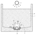
図1は本発明の実施の形態における廃棄物処理設備の概略縦断面図、図2は図1のA−A断面図である。 FIG. 1 is a schematic longitudinal sectional view of a waste treatment facility according to an embodiment of the present invention, and FIG. 2 is a sectional view taken along line AA of FIG.
図1および図2において、本発明の実施の形態における廃棄物処理設備は、廃棄物が埋め立てられて廃棄物層Rが形成される埋立槽1と、この埋立槽1の底部に形成される石積み濾床2と、廃棄物層Rから発生し、石積み濾床2内を通過した水を集水して石積み濾床2外へ排水する集排水装置を構成する集排水管3と、集排水管3の排水を一時的に溜める浸出水調整部としての浸出水調整槽4と、浸出水調整槽4内の水を廃棄物層Rの上方の散水管5まで汲み上げる水中ポンプ6および配管7とを有する。また、この廃棄物処理設備には、埋立槽1および浸出水調整槽4への雨水の流入を防止するための覆蓋8を有する。
1 and 2, the waste treatment facility according to the embodiment of the present invention includes a
石積み濾床2は、濾材としての砕石や栗石などの石を、例えば1.0〜1.5mの高さで積み上げたものである。これらの石の直径は、例えば200〜300mm程度である。これらの石には、廃棄物層Rから発生する浸出水が接触することによって表面に好気性生物膜が生成される。この好気性生物膜により、浸出水中の有機物は吸着および分解(酸化分解)される。なお、石積み濾床2は、浸出水の接触によって表面に好気性生物膜が生成されるものであれば良く、プラスチック塊やコンクリート塊などにより形成することも可能である。
The
集排水管3は、石積み濾床2内を通過した水を集水して石積み濾床2外の浸出水調整槽4へ排水するものである。集排水管3の直径は、例えば400〜1000mm程度である。集排水管3の胴体には、複数の集水口(図示せず。)が設けられている。埋立槽1の下面は、集排水管3が設けられている中央部分が低くなるように傾斜面が形成されており、廃棄物層Rを通過した水は集排水管3部分に集まり、複数の集水口から集排水管3内に流入して、浸出水調整槽4へと排水される。
The
散水管5は、水中ポンプ6および配管7とともに散水装置を構成するものであり、浸出水調整槽4から汲み上げた水を廃棄物層Rへ広く散水するものである。なお、図2においては、散水管5は1本であるが、埋立槽1内の廃棄物層Rへ満遍なく散水するために、必要に応じて複数本を並設することも可能である。なお、図1〜図3において散水管5は空気中に設けているが、廃棄物層Rの中、具体的には表面から0.5〜1.0mの深さの地中に設けることもある。
The
上記構成の廃棄物処理設備では、好気性生物膜が表面に生成される濾材からなる石積み濾床2上部に廃棄物層Rが形成されることで、廃棄物層Rから発生した浸出水は石積み濾床2内を通過し、石表面の好気性生物膜と接触する。これにより、浸出水中の有機物(BOD成分)は、石表面の好気性生物膜により吸着および分解され、浄化される。
In the waste treatment facility configured as described above, the waste layer R is formed on the top of the
こうして、石積み濾床2内を通過して浄化された水は、集排水管3により集水され、浸出水調整槽4へと排水される。そして、浸出水調整槽4に設置される水中ポンプ6および配管7により廃棄物層R上の散水管5へ送水され、散水管5から繰り返し廃棄物層R上に散水されることにより、廃棄物層Rの有機物および有機物の分解により生じた汚水を吸収(洗い出し)して、石積み濾床2内を通過する。
Thus, the water purified through the
なお、この廃棄物処理設備では、好気性生物膜による浸出水の酸化分解に必要な酸素は、集排水管3により供給される。図1に示すように集排水管3の排水口30は浸出水調整槽4の水面よりも上に設けられており、浸出水調整槽4の水面は水位センサーにより常に排水口30よりも下となるように管理されている。これにより、図2に示すように集排水管3内は、下部は処理水が通過する通水部31、上部は空気が通過する通気部32となるので、この集排水管3の通気部32を通じて空気が石積み濾床2の内部へ供給される。
In this waste treatment facility, oxygen necessary for the oxidative decomposition of the leachate by the aerobic biofilm is supplied through the
また、この廃棄物処理設備では、石積み濾床2下部への通気によって、石積み濾床2の石表面の好気性生物膜に空気が供給されるとともに、廃棄物層Rにも空気が供給され、廃棄物層Rにおいて好気性微生物による酸化分解が行われる。このとき、廃棄物層Rの内部温度は40〜70℃程度に上昇しているので生物活性が増すとともに、石積み濾床2下部から供給される空気は廃棄物層R内を上昇し、廃棄物層R内において好気性微生物による酸化分解に利用される。これにより、廃棄物層Rの廃棄物は堆肥化される。
Further, in this waste treatment facility, air is supplied to the aerobic biofilm on the stone surface of the
以上のように、本実施形態における廃棄物処理設備では、活性汚泥法、接触曝気法、回転円板法、担体法や膜分離活性汚泥法等の高度な生物処理方法を用いずに、簡易な構成で浸出水中の有機物を処理することができる。したがって、建設費は安価となり、維持管理のための技術者の確保が容易となり、維持管理費も小さくできる。 As described above, the waste treatment facility in the present embodiment is simple without using an advanced biological treatment method such as an activated sludge method, a contact aeration method, a rotating disk method, a carrier method or a membrane separation activated sludge method. The composition can treat organic matter in the leachate. Therefore, the construction cost is low, it is easy to secure engineers for maintenance, and the maintenance cost can be reduced.
また、この廃棄物処理設備では、石積み濾床2下部への通気によって、石表面の好気性生物膜に酸素が供給されるとともに、廃棄物層R内にも酸素が供給され、廃棄物層R内において好気性微生物による酸化分解が行われるので、廃棄物層Rの廃棄物が堆肥化され、再利用することが可能である。その後、埋立槽1内へ新しい廃棄物を投入して、廃棄物が安定するまでの一定期間浸出水を循環させることにより、浸出水を処理することが可能である。
Further, in this waste treatment facility, oxygen is supplied to the aerobic biofilm on the stone surface by aeration to the lower part of the
また、本実施形態における廃棄物処理設備では、自然通気により石積み濾床2および廃棄物層Rの内部まで新鮮空気が供給されるので省エネルギーであり、好気性生物膜および好気性微生物による酸化分解が活発に行われる。また、図1の例では、上部に送風機9およびガス処理設備10を有しており、送風機9により新鮮な外気を強制的に設備内に取り込み、この取り込んだ空気量と同量の排気ガスを、ガス処理設備10を介して外部へ排出するようにしている。
Further, in the waste treatment facility in this embodiment, since fresh air is supplied to the inside of the
あるいは、送風機9に代えて図3に示すように吸引ファン11をガス処理設備10の前段に設けることも可能である。この場合も同様に、吸引ファン11により新鮮な外気を強制的に開口12から設備内に取り込んで、この取り込んだ空気量と同量の排気ガスを、ガス処理設備10を介して外部へ排出すれば良い。なお、強制通気のための送風機9や吸引ファン11は、太陽光や風力などの自然エネルギーを利用して動作させることが好ましい。
Alternatively, the
また、本実施形態における廃棄物処理設備では、廃棄物層Rの上方を覆う覆蓋8を有するので、廃棄物層R内への雨水の流入が防止されている。したがって、浸出水は廃棄物層Rの保有水と廃棄物層Rの有機物の酸化分解により生じた水のみとなるので、浸出水量の増加を防止することができ、運転費用を減らすことができる。
Moreover, since the waste treatment facility in the present embodiment includes the
本発明の廃棄物処理方法および廃棄物処理設備は、廃棄物層から発生する浸出水を処理して廃棄物を処理する方法および設備として有用である。特に、本発明は、活性汚泥法、接触曝気法、回転円板法、担体法や膜分離活性汚泥法等の高度な生物処理方法を用いずに、簡易な構成で浸出水中の有機物を処理し、さらにこの浸出水を利用して廃棄物をも処理することが可能な廃棄物処理方法および廃棄物処理設備として好適である。 The waste treatment method and waste treatment facility of the present invention are useful as a method and equipment for treating leachate generated from a waste layer to treat waste. In particular, the present invention treats organic matter in leachate with a simple configuration without using advanced biological treatment methods such as activated sludge method, contact aeration method, rotating disk method, carrier method and membrane separation activated sludge method. Furthermore, it is suitable as a waste processing method and a waste processing facility capable of processing waste using this leachate.
R 廃棄物層
1 埋立槽
2 石積み濾床
3 集排水管
4 浸出水調整槽
5 散水管
6 水中ポンプ
7 配管
8 覆蓋
9 送風機
10 ガス処理設備
11 吸引ファン
12 開口
30 排水口
31 通水部
32 通気部
Claims (7)
前記廃棄物層から発生し、前記濾床内を通過した水を集水して前記濾床外へ排水すること、
この排水を前記廃棄物層上に散水すること、
前記濾床の下部に通気すること
を含む廃棄物処理方法。 Forming a waste layer on top of the filter bed consisting of filter media on which an aerobic biofilm is produced,
Collecting the water generated from the waste layer and passing through the filter bed and draining it outside the filter bed;
Watering this waste water on the waste layer,
A waste treatment method comprising ventilating a lower part of the filter bed.
前記廃棄物層から発生し、前記濾床内を通過した水を集水して前記濾床外へ排水する集排水装置と、
前記濾床の下部に通気する通気部と、
前記集排水装置の排水を前記廃棄物層上に散水する散水装置と
を有する廃棄物処理設備。 A filter bed in which an aerobic biofilm is composed of a filter medium formed on the surface, and a waste layer is formed on the top;
A drainage device that collects the water generated from the waste layer and passed through the filter bed and drains it outside the filter bed;
A vent for venting the lower part of the filter bed;
A waste treatment facility having a watering device for sprinkling the wastewater of the water collecting and draining device onto the waste layer.
前記散水装置は、前記浸出水調整部の水を前記廃棄物層上まで汲み上げるためのポンプを備えたものである
請求項4記載の廃棄物処理設備。 A leachate adjustment section for collecting the waste water of the drainage device;
5. The waste treatment facility according to claim 4, wherein the watering device includes a pump for pumping water from the leachate adjusting unit to the waste layer.
Priority Applications (1)
| Application Number | Priority Date | Filing Date | Title |
|---|---|---|---|
| JP2008320074A JP2010142693A (en) | 2008-12-16 | 2008-12-16 | Method and equipment for waste treatment |
Applications Claiming Priority (1)
| Application Number | Priority Date | Filing Date | Title |
|---|---|---|---|
| JP2008320074A JP2010142693A (en) | 2008-12-16 | 2008-12-16 | Method and equipment for waste treatment |
Publications (1)
| Publication Number | Publication Date |
|---|---|
| JP2010142693A true JP2010142693A (en) | 2010-07-01 |
Family
ID=42563685
Family Applications (1)
| Application Number | Title | Priority Date | Filing Date |
|---|---|---|---|
| JP2008320074A Pending JP2010142693A (en) | 2008-12-16 | 2008-12-16 | Method and equipment for waste treatment |
Country Status (1)
| Country | Link |
|---|---|
| JP (1) | JP2010142693A (en) |
Cited By (2)
| Publication number | Priority date | Publication date | Assignee | Title |
|---|---|---|---|---|
| JP2013094724A (en) * | 2011-10-31 | 2013-05-20 | Fukuoka Univ | Waste disposal method and waste disposal equipment |
| JP2013226483A (en) * | 2012-04-24 | 2013-11-07 | Ohbayashi Corp | Volume reduction system and volume reduction method for plant residue |
Citations (4)
| Publication number | Priority date | Publication date | Assignee | Title |
|---|---|---|---|---|
| JPS544444A (en) * | 1977-06-14 | 1979-01-13 | Taisei Corp | Method of reclaiming land from waste |
| JPS5413634A (en) * | 1977-07-01 | 1979-02-01 | Tadasumi Arima | Method of reclaiming land from general and industrial waste |
| JPS6447486A (en) * | 1987-08-14 | 1989-02-21 | Masataka Hanashima | Waste discarding facility structure, its usage, and vent pipe for decomposing organic matter used therefor |
| JP2004351240A (en) * | 2003-05-27 | 2004-12-16 | Kubota Corp | Landfill waste layer structure |
-
2008
- 2008-12-16 JP JP2008320074A patent/JP2010142693A/en active Pending
Patent Citations (4)
| Publication number | Priority date | Publication date | Assignee | Title |
|---|---|---|---|---|
| JPS544444A (en) * | 1977-06-14 | 1979-01-13 | Taisei Corp | Method of reclaiming land from waste |
| JPS5413634A (en) * | 1977-07-01 | 1979-02-01 | Tadasumi Arima | Method of reclaiming land from general and industrial waste |
| JPS6447486A (en) * | 1987-08-14 | 1989-02-21 | Masataka Hanashima | Waste discarding facility structure, its usage, and vent pipe for decomposing organic matter used therefor |
| JP2004351240A (en) * | 2003-05-27 | 2004-12-16 | Kubota Corp | Landfill waste layer structure |
Cited By (2)
| Publication number | Priority date | Publication date | Assignee | Title |
|---|---|---|---|---|
| JP2013094724A (en) * | 2011-10-31 | 2013-05-20 | Fukuoka Univ | Waste disposal method and waste disposal equipment |
| JP2013226483A (en) * | 2012-04-24 | 2013-11-07 | Ohbayashi Corp | Volume reduction system and volume reduction method for plant residue |
Similar Documents
| Publication | Publication Date | Title |
|---|---|---|
| CN104874285B (en) | A kind of compound bio deodoration system and method for handling atm number high concentration foul smell | |
| KR101218767B1 (en) | Vegetation Wetland System for Treatment of Urban Non-Contaminant Pollutants by Aerobic and Anaerobic Decomposition | |
| CN103880193B (en) | Build the method for vertical current constructed wetland processing breeding wastewater based on waterworks sludge | |
| JP2000325976A (en) | Biological / oxidative filtration equipment | |
| CN109574392A (en) | A kind of integrated apparatus and method purifying black-odor riverway sewage | |
| CN1631817A (en) | Integrated anaerobic-wetland wastewater treatment apparatus and method therefor | |
| CN105129969A (en) | Periphery filtering effluent biochemistry sedimentation tank | |
| CN108751582A (en) | A kind of three-dimensional Ecology purifying integral system for black and odorous water reparation | |
| KR101549201B1 (en) | Deodorizing system equipped with bio-filter | |
| JP5273608B2 (en) | Leachate treatment method and leachate treatment facility at waste disposal site | |
| JP4408088B2 (en) | Tunnel equipped with purification device and method for purifying pollutant gas in tunnel | |
| KR100920090B1 (en) | Advanced treatment equipment for recycling wastewater | |
| JP5681439B2 (en) | Sewage treatment equipment and drainage toilet equipment | |
| KR101340353B1 (en) | Sewage treatment facility using biofilter with purification waterweed | |
| CN106904792A (en) | For the artificial marsh sewage treatment system in city suburbs montane park | |
| CN214457121U (en) | Bury formula integration sewage treatment device | |
| KR200220403Y1 (en) | Domestic wastewater treatment device using the recycling semi-wetland method | |
| WO2019053252A1 (en) | Modular bio bed and ventilated system for waste water treatment | |
| JP3735817B2 (en) | Organic wastewater treatment apparatus and treatment method | |
| CN107089768A (en) | A kind of sewage disposal and the method and system for reclaiming water body resource | |
| JP2005342613A (en) | Human waste purification device | |
| JP2007050326A (en) | Final disposal site operation method, final disposal facility | |
| CN111847759A (en) | Process flow of integrated sewage treatment equipment | |
| CN104086059A (en) | Constructed wetland system | |
| CN104085999A (en) | Assembled constructed wetland system |
Legal Events
| Date | Code | Title | Description |
|---|---|---|---|
| A621 | Written request for application examination |
Free format text: JAPANESE INTERMEDIATE CODE: A621 Effective date: 20111019 |
|
| A977 | Report on retrieval |
Free format text: JAPANESE INTERMEDIATE CODE: A971007 Effective date: 20120224 |
|
| A131 | Notification of reasons for refusal |
Free format text: JAPANESE INTERMEDIATE CODE: A131 Effective date: 20120703 |
|
| A521 | Request for written amendment filed |
Free format text: JAPANESE INTERMEDIATE CODE: A523 Effective date: 20120807 |
|
| A02 | Decision of refusal |
Free format text: JAPANESE INTERMEDIATE CODE: A02 Effective date: 20120828 |