JP2010142730A - Wastewater treatment system - Google Patents
Wastewater treatment system Download PDFInfo
- Publication number
- JP2010142730A JP2010142730A JP2008322594A JP2008322594A JP2010142730A JP 2010142730 A JP2010142730 A JP 2010142730A JP 2008322594 A JP2008322594 A JP 2008322594A JP 2008322594 A JP2008322594 A JP 2008322594A JP 2010142730 A JP2010142730 A JP 2010142730A
- Authority
- JP
- Japan
- Prior art keywords
- adsorption
- wastewater treatment
- desorption
- organic solvent
- wastewater
- Prior art date
- Legal status (The legal status is an assumption and is not a legal conclusion. Google has not performed a legal analysis and makes no representation as to the accuracy of the status listed.)
- Pending
Links
- 238000004065 wastewater treatment Methods 0.000 title claims abstract description 154
- 238000001179 sorption measurement Methods 0.000 claims abstract description 88
- 238000002336 sorption--desorption measurement Methods 0.000 claims abstract description 62
- 239000003960 organic solvent Substances 0.000 claims abstract description 55
- XLYOFNOQVPJJNP-UHFFFAOYSA-N water Substances O XLYOFNOQVPJJNP-UHFFFAOYSA-N 0.000 claims abstract description 52
- 239000002351 wastewater Substances 0.000 claims abstract description 44
- 238000002485 combustion reaction Methods 0.000 claims abstract description 16
- 238000003795 desorption Methods 0.000 claims description 56
- 238000000034 method Methods 0.000 claims description 36
- OKTJSMMVPCPJKN-UHFFFAOYSA-N Carbon Chemical class [C] OKTJSMMVPCPJKN-UHFFFAOYSA-N 0.000 claims description 22
- 238000007599 discharging Methods 0.000 claims description 8
- 229920000049 Carbon (fiber) Polymers 0.000 claims description 7
- 229910021536 Zeolite Inorganic materials 0.000 claims description 6
- HNPSIPDUKPIQMN-UHFFFAOYSA-N dioxosilane;oxo(oxoalumanyloxy)alumane Chemical compound O=[Si]=O.O=[Al]O[Al]=O HNPSIPDUKPIQMN-UHFFFAOYSA-N 0.000 claims description 6
- 239000010457 zeolite Substances 0.000 claims description 6
- 238000007664 blowing Methods 0.000 claims description 2
- 239000003463 adsorbent Substances 0.000 abstract description 77
- 238000010438 heat treatment Methods 0.000 description 12
- 230000018044 dehydration Effects 0.000 description 7
- 238000006297 dehydration reaction Methods 0.000 description 7
- 239000011148 porous material Substances 0.000 description 7
- 238000004140 cleaning Methods 0.000 description 6
- 238000010586 diagram Methods 0.000 description 6
- 239000008187 granular material Substances 0.000 description 5
- 239000012530 fluid Substances 0.000 description 4
- BASFCYQUMIYNBI-UHFFFAOYSA-N platinum Chemical compound [Pt] BASFCYQUMIYNBI-UHFFFAOYSA-N 0.000 description 4
- 230000008929 regeneration Effects 0.000 description 4
- 238000011069 regeneration method Methods 0.000 description 4
- 241000264877 Hippospongia communis Species 0.000 description 3
- 238000005338 heat storage Methods 0.000 description 3
- 239000010842 industrial wastewater Substances 0.000 description 3
- CURLTUGMZLYLDI-UHFFFAOYSA-N Carbon dioxide Chemical compound O=C=O CURLTUGMZLYLDI-UHFFFAOYSA-N 0.000 description 2
- 239000003054 catalyst Substances 0.000 description 2
- 238000007084 catalytic combustion reaction Methods 0.000 description 2
- 230000003197 catalytic effect Effects 0.000 description 2
- 230000007423 decrease Effects 0.000 description 2
- 230000000694 effects Effects 0.000 description 2
- 239000000463 material Substances 0.000 description 2
- VNWKTOKETHGBQD-UHFFFAOYSA-N methane Chemical class C VNWKTOKETHGBQD-UHFFFAOYSA-N 0.000 description 2
- 244000005700 microbiome Species 0.000 description 2
- 238000007254 oxidation reaction Methods 0.000 description 2
- 229910052697 platinum Inorganic materials 0.000 description 2
- 238000000746 purification Methods 0.000 description 2
- 239000010865 sewage Substances 0.000 description 2
- 241000195493 Cryptophyta Species 0.000 description 1
- 229910002092 carbon dioxide Inorganic materials 0.000 description 1
- 239000001569 carbon dioxide Substances 0.000 description 1
- 238000000354 decomposition reaction Methods 0.000 description 1
- 239000000428 dust Substances 0.000 description 1
- 238000000605 extraction Methods 0.000 description 1
- 239000002657 fibrous material Substances 0.000 description 1
- 238000009434 installation Methods 0.000 description 1
- 229910052751 metal Inorganic materials 0.000 description 1
- 239000002184 metal Substances 0.000 description 1
- 230000004048 modification Effects 0.000 description 1
- 238000012986 modification Methods 0.000 description 1
- 238000006864 oxidative decomposition reaction Methods 0.000 description 1
- 230000000704 physical effect Effects 0.000 description 1
- 238000010926 purge Methods 0.000 description 1
- 238000011084 recovery Methods 0.000 description 1
- 230000001172 regenerating effect Effects 0.000 description 1
- 239000007787 solid Substances 0.000 description 1
- 238000005507 spraying Methods 0.000 description 1
- 239000000126 substance Substances 0.000 description 1
Images

Landscapes
- Water Treatment By Sorption (AREA)
- Solid-Sorbent Or Filter-Aiding Compositions (AREA)
Abstract
Description
本発明は、有機溶剤を含有する排水から有機溶剤を除去することで当該排水を清浄化する排水処理システムに関し、特に、各種工場や研究施設等から排出される有機溶剤を含有する産業排水から有害有機溶剤を効率的に除去することで当該産業排水を清浄化する排水処理システムに関する。 The present invention relates to a wastewater treatment system that purifies the wastewater by removing the organic solvent from the wastewater containing the organic solvent, and is particularly harmful from industrial wastewater containing the organic solvent discharged from various factories and research facilities. The present invention relates to a wastewater treatment system that purifies industrial wastewater by efficiently removing organic solvents.
従来、有機溶剤を含有する排水を清浄化する排水処理装置として、活性炭等の吸着材を利用した吸着式排水処理装置が広く利用されている。この吸着式排水処理装置においては、吸着材が交換可能なカートリッジにて構成されており、当該吸着材に排水を接触させることで有機溶剤が吸着材によって吸着されて除去され、これにより排水が清浄化されてクリーンな浄水として排出される。 Conventionally, an adsorption-type wastewater treatment device using an adsorbent such as activated carbon has been widely used as a wastewater treatment device for purifying wastewater containing an organic solvent. In this adsorption-type wastewater treatment device, the adsorbent is composed of a replaceable cartridge, and the organic solvent is adsorbed and removed by the adsorbent by bringing wastewater into contact with the adsorbent, thereby cleaning the wastewater. And discharged as clean water.
しかしながら、吸着式排水処理装置においては、有機溶剤を一定時間吸着し続けることによって吸着材の吸着能力が飽和に達すれば、それ以降吸着が実質的には行なわれず、吸着材を新品へ交換するか、あるいは一旦装置から吸着材を取り外して再生処理を行なうことが必要になる。したがって、このような吸着式排水処理装置を備えた排水処理システムとした場合には、連続的に排水を処理することができず、排水処理システム自体をその都度停止させることが必要であった。 However, in the adsorption-type wastewater treatment device, if the adsorption capacity of the adsorbent reaches saturation by continuing to adsorb the organic solvent for a certain period of time, the adsorption is not substantially performed thereafter, and the adsorbent is replaced with a new one. Alternatively, it is necessary to remove the adsorbent from the apparatus and perform the regeneration process. Therefore, in the case of a wastewater treatment system provided with such an adsorption-type wastewater treatment apparatus, wastewater cannot be treated continuously, and it is necessary to stop the wastewater treatment system itself each time.
また、水の清浄化は、空気の清浄化とは異なり、微生物の繁殖が不可避であり、吸着材の寿命は短くなってしまう。したがって、吸着式排水処理装置を備えた排水処理システムとした場合には、上述した吸着材の交換作業や再生処理作業を頻繁に行なう必要が生じ、その労力やランニングコストが増大するといった問題もあった。 In addition, unlike the purification of air, the purification of water inevitably causes the growth of microorganisms, and the life of the adsorbent is shortened. Therefore, in the case of a wastewater treatment system equipped with an adsorption-type wastewater treatment device, it is necessary to frequently perform the above-described adsorption material replacement work and regeneration treatment work, which increases the labor and running costs. It was.
このような問題を解決するためには、多量の吸着材を用いて交換周期を延長させることも考えられるが、装置の大型化や設置コストの増大が不可避であり、必ずしも有効な対策とはなり得ない。また、特開平9−77508号公報(特許文献1)には、吸着材としての活性炭の表面を適度に疎水化することで吸着能力の向上を図り、これにより交換周期を延長させることが提案されているが、微量の有機溶剤を除去する場合には有効であっても、多量の有機溶剤を高効率で除去することが要請される場合には根本的な解決策とはならず、特に工場や研究施設等から排出される多量の有機溶剤を含む産業排水の処理には必ずしも適したものとは言えない。 In order to solve such a problem, it is conceivable to extend the replacement cycle by using a large amount of adsorbent, but it is inevitable to increase the size of the device and increase the installation cost, which is not necessarily an effective measure. I don't get it. Japanese Patent Laid-Open No. 9-77508 (Patent Document 1) proposes that the surface of activated carbon as an adsorbent is appropriately hydrophobized to improve the adsorption capacity, thereby extending the exchange period. However, even if it is effective when removing a small amount of organic solvent, it is not a fundamental solution when it is required to remove a large amount of organic solvent with high efficiency. It is not necessarily suitable for the treatment of industrial wastewater containing a large amount of organic solvent discharged from research facilities.
また一般に、吸着材の吸着性能は、その使用に伴って時間とともに低下するため、安定的な排水の処理性能を維持するためには、吸着材を早めに交換することが必要になる。したがって、吸着式排水処理装置を備えた排水処理システムにおいて、安定的な排水の処理性能を得るためには、吸着材の交換周期を早めることでこれを維持する必要があり、排水処理システムを頻繁に停止させる必要があった。
したがって、本発明は、上述の如くの問題を解決すべくなされたものであり、より長期間にわたってシステムを停止させることなく排水の清浄化が可能で、高効率にかつ安定的に排水を処理できる排水処理システムを提供することを目的とする。 Therefore, the present invention has been made to solve the above-described problems, and it is possible to clean the wastewater without stopping the system for a longer period of time, and the wastewater can be treated efficiently and stably. An object is to provide a wastewater treatment system.
本発明に基づく排水処理システムは、有機溶剤を含有する排水から有機溶剤を除去することで当該排水を清浄化するものであって、吸着式排水処理装置と、吸脱着式排水処理装置と、燃焼装置とを備えている。上記吸着式排水処理装置は、排水を接触させることで有機溶剤を吸着する第1吸着素子を含み、上記第1吸着素子に排水を供給することで有機溶剤を上記第1吸着素子に吸着させて一次処理水として排出するものである。上記吸脱着式排水処理装置は、上記吸着式排水処理装置に接続され、上記吸着式排水処理装置から排出された一次処理水を接触させることで有機溶剤を吸着し、加熱ガスを接触させることで吸着した有機溶剤を脱着する第2吸着素子を含み、上記第2吸着素子に一次処理水を供給することで有機溶剤を上記第2吸着素子に吸着させて二次処理水として排出し、上記第2吸着素子に加熱ガスを供給することで有機溶剤を上記第2吸着素子から脱着させて有機溶剤を含有する脱着ガスとして排出するものである。ここで、上記吸着式排水処理装置は、上記第1吸着素子が交換可能に構成されたものであり、上記吸脱着式排水処理装置は、上記第2吸着素子の脱着処理が完了した部分を吸着処理を行なう部分に移行させるとともに上記第2吸着素子の吸着処理が完了した部分を脱着処理を行なう部分に移行させることで連続的に一次処理水を処理可能なものである。上記燃焼装置は、上記吸脱着式排水処理装置に接続され、上記吸脱着式排水処理装置から排出された脱着ガスを燃焼させて酸化分解させるものである。 The wastewater treatment system according to the present invention is to purify the wastewater by removing the organic solvent from the wastewater containing the organic solvent, the adsorption wastewater treatment device, the adsorption / desorption wastewater treatment device, and the combustion Device. The adsorption-type wastewater treatment apparatus includes a first adsorption element that adsorbs an organic solvent by bringing wastewater into contact with the organic solvent, and the organic solvent is adsorbed by the first adsorption element by supplying wastewater to the first adsorption element. It is discharged as primary treated water. The adsorption / desorption type wastewater treatment device is connected to the adsorption type wastewater treatment device, adsorbs the organic solvent by contacting the primary treated water discharged from the adsorption type wastewater treatment device, and makes the heated gas contact. A second adsorbing element for desorbing the adsorbed organic solvent, and supplying the first treated water to the second adsorbing element so that the organic solvent is adsorbed on the second adsorbing element and discharged as secondary treated water; By supplying a heating gas to the two adsorption elements, the organic solvent is desorbed from the second adsorption element and discharged as a desorption gas containing the organic solvent. Here, the adsorption-type wastewater treatment device is configured such that the first adsorption element is replaceable, and the adsorption / desorption-type wastewater treatment device adsorbs a portion where the desorption treatment of the second adsorption element is completed. The primary treated water can be continuously treated by shifting to the portion where the treatment is performed and moving the portion where the adsorption treatment of the second adsorption element is completed to the portion where the desorption treatment is performed. The combustion apparatus is connected to the adsorption / desorption type wastewater treatment apparatus, and burns and deoxidizes the desorption gas discharged from the adsorption / desorption type wastewater treatment apparatus.
上記本発明に基づく排水処理システムにあっては、上記吸脱着式排水処理装置が、上記第2吸着素子にガスを吹き付けることで上記第2吸着素子に付着した余剰の排水を吹き飛ばしてこれを除去排水として排出することが好ましい。その場合には、上記吸脱着式排水処理装置から排出された除去排水が、一次処理水として上記吸脱着式排水処理装置に再度供給されるように構成されていることが好ましい。 In the wastewater treatment system according to the present invention, the adsorption / desorption type wastewater treatment apparatus blows off excess wastewater adhering to the second adsorption element by blowing gas to the second adsorption element to remove it. It is preferable to discharge as waste water. In that case, it is preferable that the removed waste water discharged from the adsorption / desorption type waste water treatment device is again supplied to the adsorption / desorption type waste water treatment device as primary treated water.
上記本発明に基づく排水処理システムにあっては、上記第1吸着素子および上記第2吸着素子のそれぞれが、活性炭、活性炭素繊維およびゼオライトからなる群から選ばれる少なくとも1の部材を含んでいることが好ましい。 In the waste water treatment system according to the present invention, each of the first adsorbing element and the second adsorbing element includes at least one member selected from the group consisting of activated carbon, activated carbon fiber, and zeolite. Is preferred.
本発明によれば、より長期間にわたってシステムを停止させることなく排水の清浄化が可能で、高効率にかつ安定的に排水を処理できる排水処理システムとすることができる。 According to the present invention, waste water can be purified without stopping the system for a longer period of time, and a waste water treatment system capable of treating waste water with high efficiency and stability can be obtained.
以下、本発明の実施の形態について、図を参照して詳細に説明する。なお、以下に示す実施の形態においては、同一または対応する部分について図中同一の符号を付し、その説明は繰り返さないことにする。 Hereinafter, embodiments of the present invention will be described in detail with reference to the drawings. In the following embodiments, the same or corresponding parts are denoted by the same reference numerals in the drawings, and description thereof will not be repeated.
(実施の形態1)
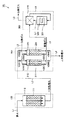
図1は、本発明の実施の形態1における排水処理システムのシステム構成図である。以下においては、この図1を参照して、本実施の形態における排水処理システム1Aの構成について説明する。
(Embodiment 1)
FIG. 1 is a system configuration diagram of a wastewater treatment system according to Embodiment 1 of the present invention. Below, with reference to this FIG. 1, the structure of the waste
図1に示すように、本実施の形態における排水処理システム1Aは、吸着式排水処理装置100と、吸脱着式排水処理装置200と、燃焼装置300とを主として備えている。
As shown in FIG. 1, the wastewater treatment system 1 </ b> A according to the present embodiment mainly includes an adsorption-type
吸着式排水処理装置100は、第1吸着素子としての吸着材111が収容された吸着槽110を有している。吸着材111は、交換可能なカートリッジにて構成されており、必要に応じて吸着槽110から取り出されて新品に交換されたり、あるいは一旦吸着槽110から取り出して再生処理が行なわれたりすることで定期的に取り替えられる。吸着材111は、排水を接触させることで排水に含有される有機溶剤を吸着する。したがって、吸着式排水処理装置100においては、吸着材111に排水を供給することで有機溶剤が吸着材111によって吸着され、これにより排水が清浄化されて一次処理水として排出されることになる。
The adsorption-type
吸着槽110には、配管ラインL1,L2が接続されている。配管ラインL1は、有機溶剤を含有する排水を吸着槽110に供給するための配管ラインであり、配管ラインL2は、吸着槽110から一次処理水を排出するための配管ラインである。
Piping lines L 1 and L 2 are connected to the
吸着式排水処理装置100から排出される一次処理水は、吸着材111の性能にもよるが、吸着式排水処理装置100に供給される排水に比べその有機溶剤の含有量は大幅に減少しているものの、僅かに有機溶剤を含んでいてよい。
Although the primary treated water discharged from the adsorption-type
吸着材111は、活性炭、活性炭素繊維またはゼオライトの少なくともいずれかを含む部材にて構成されている。好適には、吸着材111としては、粒状、粒体状、ハニカム状等の活性炭やゼオライトが利用されるが、より好適には、活性炭素繊維が利用される。活性炭素繊維は、表面にミクロ孔を有する繊維状構造を有しているため、水との接触効率が高く、特に水中の有機溶剤の吸着速度が速くなり、他の吸着素子に比べて極めて高い吸着効率を実現できる部材である。
The
吸脱着式排水処理装置200は、第2吸着素子としての吸着材211,221がそれぞれ収容された第1処理槽210および第2処理槽220を有している。吸着材211,221は、一次処理水を接触させることで一次処理水に含有される有機溶剤を吸着する。したがって、吸脱着式排水処理装置200においては、吸着材211,221に一次処理水を供給することで有機溶剤が吸着材211,221によって吸着され、これにより一次処理水が清浄化されて二次処理水として排出されることになる。また、吸着材211,221は、加熱ガスを接触させることで吸着した有機溶剤を脱着する。したがって、吸脱着式排水処理装置200においては、吸着材211,221に加熱ガスを供給することで有機溶剤が吸着材211,221から脱着され、これにより加熱ガスが有機溶剤を含有する脱着ガスとして排出されることになる。ここで、加熱ガスとしては、ヒータ等によって予め加熱された高温の空気等が利用可能であり、より好適には、高温の脱水空気が利用される。
The adsorption / desorption type waste
第1処理槽210および第2処理槽220には、配管ラインL2,L3,L4,L5がそれぞれ接続されている。配管ラインL2は、吸着式排水処理装置100から排出された一次処理水を第1処理槽210および第2処理槽220に供給するための配管ラインであり、バルブV201,V202によって第1処理槽210および第2処理槽220に対する接続/非接続状態が切り替えられる。配管ラインL3は、加熱ガスを第1処理槽210および第2処理槽220に供給するための配管ラインであり、バルブV203,V204によって第1処理槽210および第2処理槽220に対する接続/非接続状態が切り替えられる。配管ラインL4は、二次処理水を第1処理槽210および第2処理槽220から排出するための配管であり、バルブV205,V206によって第1処理槽210および第2処理槽220に対する接続/非接続状態が切り替えられる。配管ラインL5は、脱着ガスを第1処理槽210および第2処理槽220から排出するための配管ラインであり、バルブV207,V208によって第1処理槽210および第2処理槽220に対する接続/非接続状態が切り替えられる。
Piping lines L2, L3, L4, and L5 are connected to the
第1処理槽210と第2処理槽220とは、上述したバルブV201〜V208の開閉を操作することによって交互に吸着槽および脱着槽として機能し、具体的には、第1処理槽210が吸着槽として機能している場合には、第2処理槽220が脱着槽として機能し、第1処理槽210が脱着槽として機能している場合には、第2処理槽220が吸着槽として機能する。すなわち、本実施の形態における吸脱着式排水処理装置200においては、吸着槽と脱着槽とが経時的に交互に切り替わるように構成されている。なお、配管ラインL2は、第1処理槽210および第2処理槽220のうち、吸着槽として機能している槽に接続されて当該吸着槽に一次処理水を供給し、配管ラインL3は、第1処理槽210および第2処理槽220のうち、脱着槽として機能している槽に接続されて当該脱着槽に加熱ガスを供給する。また、配管ラインL4は、第1処理槽210および第2処理槽220のうち、吸着槽として機能している槽に接続されて当該吸着槽から二次処理水を排出し、配管ラインL5は、第1処理槽210および第2処理槽220のうち、脱着槽として機能している槽に接続されて脱着ガスを排出する。
The
なお、吸脱着式排水処理装置200から排出される二次処理水は、吸着式排水処理装置100から排出される一次処理水に比べ、さらにその有機溶剤の含有量は大幅に減少しており、そのまま通常の下水として処理が可能な程度にまで清浄化されたものとなる。
In addition, the secondary treated water discharged from the adsorption / desorption type waste
吸着材211,221は、活性炭、活性炭素繊維またはゼオライトの少なくともいずれかを含む部材にて構成されている。好適には、吸着材211,221としては、粒状、粒体状、ハニカム状等の活性炭やゼオライトが利用されるが、より好適には、活性炭素繊維が利用される。活性炭素繊維は、表面にミクロ孔を有する繊維状構造を有しているため、水との接触効率が高く、特に水中の有機溶剤の吸着速度が速くなり、他の吸着素子に比べて極めて高い吸着効率を実現できる部材である。
The
吸着材211,221として利用可能な活性炭素繊維の物性は、特に限定されるものではないが、BET比表面積が700〜2000m2/g、細孔容積が0.4〜0.9cm3/g、平均細孔径が17〜18Åのものが好ましい。これは、BET比表面積が700m2/g未満、細孔容積が0.4m3/g未満、平均細孔径が17Å未満のものでは、有機溶剤の吸着量が低くなるためであり、またBET比表面積が2000m2/gを超え、細孔容積が0.9m3/gを超え、平均細孔径が18Åを超えるのものでは、細孔径が大きくなることで分子量の小さな物質等の吸着能力が低下したり、強度が弱くなったり、素材のコストが高くなって経済的に不利になったりするためである。
The physical properties of the activated carbon fibers that can be used as the
燃焼装置300は、吸脱着式排水処理装置200から排出される脱着ガスを燃焼させて酸化分解させるための装置であり、配管ラインL5,L6,L7,L8に接続されている。燃焼装置300は、熱交換器310と加熱炉320とを有しており、熱交換器310は、加熱炉320に導入される脱着ガスを予め予熱するためのものであり、加熱炉320は、電熱ヒータ321を用いて導入された脱着ガスを燃焼させるためのものである。配管ラインL5は、吸脱着式排水処理装置200から排出された脱着ガスを熱交換器310に供給するための配管ラインであり、配管ラインL6は、熱交換器310で予熱された脱着ガスを加熱炉320に導入するための配管ラインである。また、配管ラインL7,L8は、加熱炉320にて脱着ガスが燃焼することによって生成される分解ガスを熱交換器310を経由させて外部に排出するための配管ラインである。
The
燃焼装置300としては、特にその種類が限定されるものではないが、たとえば脱着ガスを650〜800℃の高温で直接的に酸化分解させる直接燃焼装置や、白金触媒等を利用して脱着ガスを触媒酸化反応させて酸化分解する触媒燃焼装置、蓄熱体を利用して熱回収を行ないつつ経済的に直接酸化分解を行なう蓄熱式直接燃焼装置、白金触媒等と蓄熱体とを組み合わせて効率的に脱着ガスを触媒酸化反応させて酸化分解する蓄熱式触媒燃焼装置等を使用することが可能である。当該燃焼装置300を用いて脱着ガスを酸化分解させることにより、有害な有機溶剤は完全に除去される。
The type of the
次に、上記図1を参照して、本実施の形態における排水処理システム1Aにおいて行なわれる排水の清浄化処理の詳細について説明する。なお、以下の説明は、吸脱着式排水処理装置200の第1処理槽210が吸着槽として機能し、第2処理槽220が脱着槽として機能している状態に基づいたものであるが、これら吸着槽と脱着槽とが入れ替わった場合にも、同様の処理が行なわれる。
Next, with reference to FIG. 1, the details of the waste water cleaning process performed in the waste
図1に示すように、排水は、配管ラインL1を経由して吸着式排水処理装置100に導入される。導入された排水は、吸着槽110に送られて吸着材111と接触し、当該排水に含有される有機溶剤が吸着材111によって吸着される。有機溶剤が吸着材111によって吸着された後の水は、配管ラインL2に導入されて一次処理水として吸着式排水処理装置100から排出される。
As shown in FIG. 1, the waste water is introduced into the adsorption-type waste
吸着式排水処理装置100から排出された一次処理水は、配管ラインL2を経由して吸脱着式排水処理装置200に導入される。導入された一次処理水は、第1処理槽210に送られて吸着材211と接触し、当該一次処理水に含有される有機溶剤が吸着材211によって吸着される。有機溶剤が吸着材211によって吸着された後の水は、配管ラインL4に導入されて二次処理水として吸脱着式排水処理装置200から排出される。吸脱着式排水処理装置200から排出された二次処理水は、その後、通常の下水としての処理がなされる。
The primary treated water discharged from the adsorption type waste
一方、吸脱着式排水処理装置200には、上記一次処理水の導入と並行して、配管ラインL3を経由して加熱ガスが導入される。導入された加熱ガスは、第2処理槽220に送られて吸着材221と接触し、吸着材221に吸着された有機溶剤を脱着させる。吸着材221から脱着された有機溶剤を含む加熱ガスは、配管ラインL5に導入されて脱着ガスとして吸脱着式排水処理装置200から排出される。
On the other hand, a heating gas is introduced into the adsorption / desorption type waste
吸脱着式排水処理装置200から排出された脱着ガスは、配管ラインL5を経由して燃焼装置300に送られ、加熱炉320にて燃焼することで酸化分解する。加熱炉320にて生成された分解ガスは、配管ラインL8に導入されて燃焼装置300から排出される。この分解ガスは、主として二酸化炭素と水蒸気とを含む人体に対して無害なガスである。
The desorption gas discharged from the adsorption / desorption type waste
以上の如くの排水処理システム1Aとすることにより、吸着式排水処理装置100のバックアップ装置として吸脱着式排水処理装置200が機能することになり、また吸脱着式排水処理装置200においては連続的に処理が行なえるため、吸着式排水処理装置100のみで排水処理システムを構築した場合に比べ、当該吸着式排水処理装置100の吸着材111の交換周期をより長くすることができる。したがって、より長期にわたってシステムを停止させることなく排水の清浄化を行なうことが可能な排水処理システムとすることができる。したがって、吸着式排水処理装置におけるカートリッジ式の吸着材の新品への交換作業や取り外しての再生処理作業の回数が減少し、その労力やランニングコストの増大を抑制することができる。
By adopting the
また、上述の如くの排水処理システム1Aとすることにより、吸脱着式排水処理装置200の第1処理槽210および第2処理槽220において吸着処理および脱着処理が交互に連続的に繰り返されることになる。このように吸着処理および脱着処理が交互に連続的に繰り返されるように構成することにより、低コストで安定的に高い能力で排水に含まれる有機溶剤を除去することができる。したがって、上記構成を採用することにより、高効率にかつ安定的に排水を清浄化処理できる排水処理システムとすることができる。なお、特に上述の如くの吸脱着式排水処理装置200とすることにより、微生物の繁殖が抑制でき、そのため藻の発生等を防止することも可能になる。
In addition, by adopting the
さらに、本実施の形態の如くの排水処理システム1Aは、吸着式排水処理装置のみを具備する既存の排水処理システムに対して、吸脱着式排水処理装置200や燃焼装置300等を増設するのみで容易に実現できるものであるため、既存の設備の有効活用が可能で経済性にも優れたものとなる。
Furthermore, the
なお、上述の本実施の形態における排水処理システム1Aにおいては、第1処理槽210および第2処理槽220が吸着槽および脱着槽に交互に入れ替わる構成の吸脱着式排水処理装置200を採用した場合を例示して説明を行なったが、これとは異なる構成の吸脱着式排水処理装置を採用してもよい。以下に、その例を図2および図3を参照して説明する。
In addition, in the waste
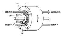
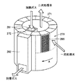
図2および図3は、本実施の形態における排水処理システムにおいて利用可能な他の吸脱着式排水処理装置の例を示す模式図である。なお、これら図2および図3においては、吸脱着式排水処理装置に具備される吸着材および当該吸着材近傍に配置される構成要素のみを図示し、その他の構成要素の図示は省略している。 FIG. 2 and FIG. 3 are schematic views showing examples of other adsorption / desorption type waste water treatment devices that can be used in the waste water treatment system according to the present embodiment. 2 and 3, only the adsorbent provided in the adsorption / desorption type waste water treatment apparatus and the components arranged in the vicinity of the adsorbent are shown, and the other components are not shown. .
図2は、円柱状の外形を有する吸着材250を利用した場合を示している。図2に示すように、円柱状の外形を有する吸着材250を利用する場合には、軸方向に流体が流動可能となるように構成された吸着材250の軸中心に回転軸261を設け、この回転軸261をアクチュエータ等によって回転駆動する。そして、吸着材250の軸方向の両端面に近接して図2においては示さない配管ラインL2〜L5(図1参照)を接続し、吸着材250の一部を吸着処理を行なうための部分(図2において符号251で示す部分)として利用し、吸着材250の他の一部を脱着処理を行なうための部分(図2において符号252で示す部分)として利用する。すなわち、吸着材250の符号251で示す部分には、軸方向の一方から一次処理水が導入され、軸方向の他方から二次処理水が導出されることになり、吸着材250の符号252で示す部分には、軸方向の一方から加熱ガスが導入され、軸方向の他方から脱着ガスが導出されることになる。
FIG. 2 shows a case where an adsorbent 250 having a cylindrical outer shape is used. As shown in FIG. 2, when using an adsorbent 250 having a cylindrical outer shape, a
ここで、図2に示す吸脱着式排水処理装置においては、吸着材250が回転軸261を回転中心として図中矢印A方向に所定の速度で回転する。これにより、吸着材250の吸着処理が完了した部分は脱着処理を行なうゾーンへと移動するとともに、吸着材250の脱着処理が完了した部分は吸着処理を行なうゾーンへと移動することになる。したがって、当該吸脱着式排水処理装置においては、同時に吸着処理と脱着処理とが行なわれることになり、連続的に清浄化処理を行なうことが可能となる。 Here, in the adsorption / desorption type waste water treatment apparatus shown in FIG. 2, the adsorbent 250 rotates at a predetermined speed in the direction of arrow A in FIG. As a result, the portion where the adsorption process of the adsorbent 250 is completed moves to the zone where the desorption process is performed, and the portion where the desorption process of the adsorbent 250 is completed moves to the zone where the adsorption process is performed. Therefore, in the adsorption / desorption type waste water treatment apparatus, the adsorption process and the desorption process are simultaneously performed, and the cleaning process can be continuously performed.
また、図3は、円筒状の外形を有する吸着材270を利用した場合を示している。図3に示すように、円筒状の外形を有する吸着材270を利用する場合には、径方向に流体が流動可能となるように、たとえば金属製の枠体285によって囲われた単位吸着ユニット275を周方向に複数並べて円筒状とし、これを図示しないアクチュエータ等によって軸中心に回転駆動する。そして、吸着材270に近接して図3においては示さない配管ラインL2〜L5(図1参照)を接続し、吸着材270の単位吸着ユニットの一部を吸着処理を行なうための部分(図3において符号271で示す部分)として利用し、単位吸着ユニットの他の一部を脱着処理を行なうための部分(図3において符号272で示す部分)として利用する。すなわち、吸着材270の符号271で示す単位吸着ユニットには、径方向外側から一次処理水が導入され、径方向内側に向けて二次処理水が導出されて軸方向の一方に向けて排出されることになり、吸着材270の符号272で示す単位吸着ユニットには、導入管281を介して径方向内側から加熱ガスが導入され、径方向外側に向けて脱着ガスが導出されて導出管282を介して排出されることになる。
FIG. 3 shows a case where an adsorbent 270 having a cylindrical outer shape is used. As shown in FIG. 3, when using an adsorbent 270 having a cylindrical outer shape, for example, a unit adsorbing unit 275 surrounded by a
ここで、図3に示す吸脱着式排水処理装置においては、吸着材270が軸中心に図中矢印A方向に所定の速度で段階的に回転する。これにより、吸着材270の吸着処理が完了した単位吸着ユニットは脱着処理を行なうゾーンへと移動するとともに、吸着材270の脱着処理が完了した単位吸着ユニットは吸着処理を行なうゾーンへと移動することになる。したがって、当該吸脱着式排水処理装置においては、同時に吸着処理と脱着処理とが行なわれることになり、連続的に清浄化処理を行なうことが可能となる。 Here, in the adsorption / desorption type waste water treatment apparatus shown in FIG. 3, the adsorbent 270 rotates stepwise around the axis at a predetermined speed in the direction of arrow A in the figure. As a result, the unit adsorption unit for which the adsorption process of the adsorbent 270 is completed moves to the zone for performing the desorption process, and the unit adsorption unit for which the desorption process for the adsorbent 270 is completed moves to the zone for performing the adsorption process. become. Therefore, in the adsorption / desorption type waste water treatment apparatus, the adsorption process and the desorption process are simultaneously performed, and the cleaning process can be continuously performed.
なお、図2および図3に示す如くの形状の吸着材250,270を利用する場合には、当該吸着材250,270を、粒状物を充填したものや繊維状物を充填したもので構成することとしてもよいが、ハニカム状の構造を有するもので構成するとなおよい。これは、吸着材250,270をハニカム状の構造を有するもので構成することにより、圧力損失を極めて低く抑えることが可能となって処理能力が増大するとともに、ゴミ等の固形物による目詰まりの発生も比較的低く抑えることができるためである。
When the
(実施の形態2)
図4は、本発明の実施の形態2における排水処理システムの構成を示す模式図である。なお、図4においては、上述の本発明の実施の形態1における排水処理システム1Aと同様の部分の図示は省略している。以下においては、この図4を参照して本実施の形態における排水処理システム1Bの構成について説明する。
(Embodiment 2)
FIG. 4 is a schematic diagram showing the configuration of the wastewater treatment system according to Embodiment 2 of the present invention. In FIG. 4, illustration of the same parts as the waste
図4に示すように、本実施の形態における排水処理システム1Bは、上述した本発明の実施の形態1における排水処理システム1Aと、吸脱着式排水処理装置200の構成において相違している。本実施の形態における排水処理システム1Bにおいては、吸脱着式排水処理装置200に加熱ガスを導入するための配管ラインL3に、吸脱着式排水処理装置200にガスを導入するための配管ラインL9が接続されており、これら配管ラインL3,L9の吸脱着式排水処理装置200に対する接続/非接続状態を切り替えるためのバルブV291,V292が、配管ラインL3,L9にそれぞれ設けられている。また、本実施の形態における排水処理システム1Bにおいては、吸脱着式排水処理装置200から脱着ガスを排出するための配管ラインL5に、吸脱着式排水処理装置200から除去排水を排出するための配管ラインL10が接続されており、これら配管ラインL5,L10の吸脱着式排水処理装置200に対する接続/非接続状態を切り替えるためのバルブV293,V294が、配管ラインL5,L10にそれぞれ設けられている。なお、配管ラインL10の他端は、吸脱着式排水処理装置200に一次処理水を導入するための配管ラインL2に接続されている。
As shown in FIG. 4, the wastewater treatment system 1B in the present embodiment is different from the above-described
本実施の形態における排水処理システム1Bの吸脱着式排水処理装置200においては、吸着処理と脱着処理との間に脱水処理(パージ処理)が実施される。具体的には、上述の本発明の実施の形態1における排水処理システム1Aの場合と同様に、吸脱着式排水処理装置200においては、バルブV201〜208の開閉が操作されることによって第1処理槽210と第2処理槽220とが交互に吸着槽および脱着槽に切り替わるが、脱着槽に切り替わった際には、まず当該脱着槽と配管ラインL9および配管ラインL10とが接続され、配管ラインL9を介して脱着槽にガスが導入されて吸着材に吹き付けられることによって吸着材の表面に付着した余剰の排水を吹き飛ばす脱水処理が行なわれ、吹き飛ばされた除去排水は、配管ラインL10および配管ラインL2を経由して吸脱着式排水処理装置200へと再度供給される。そして、当該脱水処理を所定時間行なった後に脱着槽と配管ラインL9および配管ラインL10の接続が解除され、配管ラインL3および配管ラインL5が脱着槽に接続されて脱着処理が行なわれる。なお、脱水処理の際に脱着槽に導入されるガスとしては、高温でより低湿なガスが利用されることが好ましく、たとえば所定の温度に昇温された乾燥空気を利用することが好適である。
In the adsorption / desorption type
以上において説明した本実施の形態における排水処理システム1Bの如くの構成を採用することにより、上述した本発明の実施の形態1における排水処理システム1Aの如くの構成を採用した場合に得られる効果に加え、吸着材211,221からの有機溶剤の脱着効率が大幅に増加するため、より高効率にかつ安定的に排水を清浄化処理できる排水処理システムとできる効果が得られる。なお、上述した本実施の形態においては、吸脱着式排水処理装置200から排出される除去排水が当該吸脱着式排水処理装置200に再度供給されるように構成した場合を例示して説明を行なったが、当該除去排水は、上述の吸着式排水処理装置100の如くの装置を別途用いて清浄化処理されるように構成してもよい。
By adopting the configuration as in the wastewater treatment system 1B in the present embodiment described above, the effect obtained when the configuration as in the
以上において説明した本発明の実施の形態1および2における排水処理システム1A,1Bの特徴的な構成は、相互に組み合わせることが可能である。たとえば、図2および図3に示した如くの構成の吸着材250,270を含む吸脱着式排水処理装置を本発明の実施の形態2における排水処理システム1Bの吸脱着式排水処理装置200に適用してもよい。なお、その場合には、吸着素子250,270の脱着処理を行なうためのゾーンに脱水処理を行なうためのゾーンが設けられ、当該脱水処理を行なうためのゾーンに位置する部分の吸着素子250,270に近接して上述した配管ラインL9,L10が接続され、吸着処理と脱着処理の間に脱水処理が行なわれるように吸脱着式排水処理装置200が構成されることになる。
The characteristic configurations of the
また、以上において説明した本発明の実施の形態1および2においては、ポンプやファン等の流体搬送手段やストレージタンク等の流体貯留手段などの構成要素を特に示すことなく説明を行なったが、これら構成要素は必要に応じて適宜の位置に配置すればよい。 Further, in the first and second embodiments of the present invention described above, the description has been made without particularly showing the components such as the fluid conveying means such as the pump and the fan and the fluid storing means such as the storage tank. What is necessary is just to arrange | position a component in an appropriate position as needed.
このように、今回開示した上記各実施の形態はすべての点で例示であって、制限的なものではない。本発明の技術的範囲は特許請求の範囲によって画定され、また特許請求の範囲の記載と均等の意味および範囲内でのすべての変更を含むものである。 Thus, the above-described embodiments disclosed herein are illustrative in all respects and are not restrictive. The technical scope of the present invention is defined by the terms of the claims, and is intended to include any modifications within the scope and meaning equivalent to the terms of the claims.
1A,1B 排水処理システム、100 吸着式排水処理装置、110 吸着槽、111 吸着材、200 吸脱着式排水処理装置、210 第1処理槽、211 吸着材、220 第2処理槽、221 吸着材、250 吸着材、261 回転軸、270 吸着材、275 単位吸着ユニット、281 導入管、282 導出管、285 枠体、300 燃焼装置、310 熱交換器、320 加熱炉、321 電熱ヒータ、L1〜L10 配管ライン、V201〜V208,V291〜V294 バルブ。 1A, 1B Wastewater treatment system, 100 adsorption wastewater treatment device, 110 adsorption tank, 111 adsorbent, 200 adsorption / desorption wastewater treatment device, 210 first treatment tank, 211 adsorbent, 220 second treatment tank, 221 adsorbent, 250 adsorbent, 261 rotating shaft, 270 adsorbent, 275 unit adsorbing unit, 281 introduction pipe, 282 lead-out pipe, 285 frame, 300 combustion device, 310 heat exchanger, 320 heating furnace, 321 electric heater, L1-L10 piping Line, V201-V208, V291-V294 valve.
Claims (4)
排水を接触させることで有機溶剤を吸着する第1吸着素子を含み、前記第1吸着素子に排水を供給することで有機溶剤を前記第1吸着素子に吸着させて一次処理水として排出する吸着式排水処理装置と、
前記吸着式排水処理装置に接続され、前記吸着式排水処理装置から排出された一次処理水を接触させることで有機溶剤を吸着し、加熱ガスを接触させることで吸着した有機溶剤を脱着する第2吸着素子を含み、前記第2吸着素子に一次処理水を供給することで有機溶剤を前記第2吸着素子に吸着させて二次処理水として排出し、前記第2吸着素子に加熱ガスを供給することで有機溶剤を前記第2吸着素子から脱着させて有機溶剤を含有する脱着ガスとして排出する吸脱着式排水処理装置と、
前記吸脱着式排水処理装置に接続され、前記吸脱着式排水処理装置から排出された脱着ガスを燃焼させて酸化分解させる燃焼装置とを備え、
前記吸着式排水処理装置は、前記第1吸着素子が交換可能に構成されたものであり、
前記吸脱着式排水処理装置は、前記第2吸着素子の脱着処理が完了した部分を吸着処理を行なう部分に移行させるとともに前記第2吸着素子の吸着処理が完了した部分を脱着処理を行なう部分に移行させることで連続的に一次処理水を処理可能なものである、排水処理システム。 A wastewater treatment system that purifies the wastewater by removing the organic solvent from the wastewater containing the organic solvent,
An adsorption type including a first adsorbing element that adsorbs an organic solvent by bringing wastewater into contact with the organic solvent, and supplying the first adsorbing element to adsorb the organic solvent to the first adsorbing element and discharging it as primary treated water. Wastewater treatment equipment,
The organic solvent is adsorbed by contacting the primary treated water discharged from the adsorption-type wastewater treatment device and contacted with the adsorption-type wastewater treatment device, and the adsorbed organic solvent is desorbed by contacting the heated gas. Including an adsorbing element, by supplying primary treated water to the second adsorbing element, the organic solvent is adsorbed by the second adsorbing element and discharged as secondary treated water, and a heated gas is supplied to the second adsorbing element. An adsorption / desorption type waste water treatment device for desorbing the organic solvent from the second adsorption element and discharging it as a desorption gas containing the organic solvent,
A combustion device connected to the adsorption / desorption type wastewater treatment device, and burning and decomposing the desorption gas discharged from the adsorption / desorption type wastewater treatment device;
The adsorption-type wastewater treatment device is configured such that the first adsorption element is replaceable,
The adsorption / desorption type wastewater treatment apparatus shifts a portion where the desorption process of the second adsorption element is completed to a portion where the adsorption process is performed, and changes a portion where the adsorption process of the second adsorption element is completed to a portion where the desorption process is performed. Wastewater treatment system that can treat primary treated water continuously by shifting.
Priority Applications (1)
| Application Number | Priority Date | Filing Date | Title |
|---|---|---|---|
| JP2008322594A JP2010142730A (en) | 2008-12-18 | 2008-12-18 | Wastewater treatment system |
Applications Claiming Priority (1)
| Application Number | Priority Date | Filing Date | Title |
|---|---|---|---|
| JP2008322594A JP2010142730A (en) | 2008-12-18 | 2008-12-18 | Wastewater treatment system |
Publications (1)
| Publication Number | Publication Date |
|---|---|
| JP2010142730A true JP2010142730A (en) | 2010-07-01 |
Family
ID=42563716
Family Applications (1)
| Application Number | Title | Priority Date | Filing Date |
|---|---|---|---|
| JP2008322594A Pending JP2010142730A (en) | 2008-12-18 | 2008-12-18 | Wastewater treatment system |
Country Status (1)
| Country | Link |
|---|---|
| JP (1) | JP2010142730A (en) |
Cited By (6)
| Publication number | Priority date | Publication date | Assignee | Title |
|---|---|---|---|---|
| WO2012020755A1 (en) * | 2010-08-11 | 2012-02-16 | 東洋紡績株式会社 | Waste water treatment system |
| JP2012035232A (en) * | 2010-08-11 | 2012-02-23 | Toyobo Co Ltd | Wastewater treatment system |
| JP2012040534A (en) * | 2010-08-23 | 2012-03-01 | Toyobo Co Ltd | Wastewater treatment system |
| JP2012040479A (en) * | 2010-08-17 | 2012-03-01 | Toyobo Co Ltd | Wastewater treatment system |
| JP2013111553A (en) * | 2011-11-30 | 2013-06-10 | Toyobo Co Ltd | Water treatment system |
| CN118724144A (en) * | 2024-07-03 | 2024-10-01 | 南京信息工程大学 | Organic wastewater sewage treatment equipment and sewage treatment method |
Citations (2)
| Publication number | Priority date | Publication date | Assignee | Title |
|---|---|---|---|---|
| JP2007283203A (en) * | 2006-04-17 | 2007-11-01 | Hitachi Ltd | Method and apparatus for treating oil field associated water |
| JP2008188493A (en) * | 2007-02-01 | 2008-08-21 | Toyobo Co Ltd | Water treatment apparatus |
-
2008
- 2008-12-18 JP JP2008322594A patent/JP2010142730A/en active Pending
Patent Citations (2)
| Publication number | Priority date | Publication date | Assignee | Title |
|---|---|---|---|---|
| JP2007283203A (en) * | 2006-04-17 | 2007-11-01 | Hitachi Ltd | Method and apparatus for treating oil field associated water |
| JP2008188493A (en) * | 2007-02-01 | 2008-08-21 | Toyobo Co Ltd | Water treatment apparatus |
Cited By (8)
| Publication number | Priority date | Publication date | Assignee | Title |
|---|---|---|---|---|
| WO2012020755A1 (en) * | 2010-08-11 | 2012-02-16 | 東洋紡績株式会社 | Waste water treatment system |
| JP2012035232A (en) * | 2010-08-11 | 2012-02-23 | Toyobo Co Ltd | Wastewater treatment system |
| CN103068740A (en) * | 2010-08-11 | 2013-04-24 | 东洋纺株式会社 | Wastewater Treatment System |
| CN104649448A (en) * | 2010-08-11 | 2015-05-27 | 东洋纺株式会社 | Waste water treatment system |
| JP2012040479A (en) * | 2010-08-17 | 2012-03-01 | Toyobo Co Ltd | Wastewater treatment system |
| JP2012040534A (en) * | 2010-08-23 | 2012-03-01 | Toyobo Co Ltd | Wastewater treatment system |
| JP2013111553A (en) * | 2011-11-30 | 2013-06-10 | Toyobo Co Ltd | Water treatment system |
| CN118724144A (en) * | 2024-07-03 | 2024-10-01 | 南京信息工程大学 | Organic wastewater sewage treatment equipment and sewage treatment method |
Similar Documents
| Publication | Publication Date | Title |
|---|---|---|
| JP2011072896A (en) | System for treating gas containing organic solvent | |
| JP5973249B2 (en) | Organic solvent-containing gas treatment system | |
| JP5029590B2 (en) | Wastewater treatment system | |
| KR101542177B1 (en) | Catalyst-oxidation processing apparatus of VOC concentration-adsorption type | |
| JP5810488B2 (en) | Wastewater treatment system | |
| JP6393965B2 (en) | Wastewater treatment system | |
| JP6311342B2 (en) | Wastewater treatment system | |
| WO2012020755A1 (en) | Waste water treatment system | |
| JP2012040534A (en) | Wastewater treatment system | |
| JP2010142792A (en) | Wastewater treatment system | |
| JP2010142728A (en) | System for treating exhaust | |
| JP2008188492A (en) | Water treatment system | |
| JP6332599B2 (en) | Water treatment system | |
| JP2010142790A (en) | System for treating exhaust | |
| JP2012035232A (en) | Wastewater treatment system | |
| JP6332586B2 (en) | Water treatment device and water treatment system | |
| JP2010142793A (en) | Wastewater treatment system | |
| JP2011072919A (en) | System for treating gas containing organic solvent | |
| JP5861547B2 (en) | Wastewater treatment system | |
| JP6428992B2 (en) | Wastewater treatment system | |
| JP2010142791A (en) | System for treating exhaust | |
| JP5565106B2 (en) | Wastewater treatment equipment | |
| JP4512993B2 (en) | Water treatment equipment | |
| JP6281392B2 (en) | Organic solvent-containing gas treatment system | |
| KR102536368B1 (en) | Odor and polluted material removal apparatus |
Legal Events
| Date | Code | Title | Description |
|---|---|---|---|
| A621 | Written request for application examination |
Free format text: JAPANESE INTERMEDIATE CODE: A621 Effective date: 20111020 |
|
| A977 | Report on retrieval |
Effective date: 20120713 Free format text: JAPANESE INTERMEDIATE CODE: A971007 |
|
| A131 | Notification of reasons for refusal |
Free format text: JAPANESE INTERMEDIATE CODE: A131 Effective date: 20120828 |
|
| A02 | Decision of refusal |
Free format text: JAPANESE INTERMEDIATE CODE: A02 Effective date: 20130108 |