JP2010142871A - Mold and method for powder compression molding - Google Patents
Mold and method for powder compression molding Download PDFInfo
- Publication number
- JP2010142871A JP2010142871A JP2008326188A JP2008326188A JP2010142871A JP 2010142871 A JP2010142871 A JP 2010142871A JP 2008326188 A JP2008326188 A JP 2008326188A JP 2008326188 A JP2008326188 A JP 2008326188A JP 2010142871 A JP2010142871 A JP 2010142871A
- Authority
- JP
- Japan
- Prior art keywords
- powder
- compression molding
- cavity
- hole
- raw material
- Prior art date
- Legal status (The legal status is an assumption and is not a legal conclusion. Google has not performed a legal analysis and makes no representation as to the accuracy of the status listed.)
- Pending
Links
Images
Landscapes
- Powder Metallurgy (AREA)
Abstract
【課題】ダイスと上パンチおよび下パンチを用いて圧縮成形を行う際に、成形時に圧縮成形体内部の気体をより効率よく排気し、気孔欠陥や密度ムラのない均質な圧縮成形体を確実に得ることのできる圧縮成形用金型を提供すること。
【解決手段】貫通孔1aを有するダイス1と、上パンチ2及び下パンチ3を備え、上パンチ2及び下パンチ3がそれぞれ上下方向に移動することにより貫通孔1a内にキャビティーCを形成し、形成されるキャビティーCに原料粉末を保持し、上パンチ2及び下パンチ3を互いに近づけることにより原料粉末を圧縮して圧縮成形体を成形するための粉末圧縮成形金型であり、原料粉末を圧縮する際にキャビティーC内に残留する気体を排気するために、ダイス1には、貫通孔1aの内壁からダイス1の外部に通じるような少なくとも一つの排気孔4が形成されている粉末圧縮成形金型を用いる。
【選択図】図2When compression molding is performed using a die, an upper punch, and a lower punch, the gas inside the compression molded body is more efficiently exhausted during molding to ensure a homogeneous compression molded body free from pore defects and density unevenness. To provide a compression mold that can be obtained.
A die 1 having a through hole 1a, an upper punch 2 and a lower punch 3 are provided, and a cavity C is formed in the through hole 1a by moving the upper punch 2 and the lower punch 3 in the vertical direction. A powder compression mold for holding a raw material powder in the cavity C to be formed and compressing the raw material powder by bringing the upper punch 2 and the lower punch 3 closer to each other to form a compression molded body. In order to evacuate the gas remaining in the cavity C when compressing the powder, the die 1 is formed with at least one exhaust hole 4 leading from the inner wall of the through hole 1a to the outside of the die 1. A compression mold is used.
[Selection] Figure 2
Description
本発明は、金属粉やセラミックス粉などの粉体を成形するための粉末圧縮成形金型と粉末圧縮成形方法に関する。 The present invention relates to a powder compression molding die and a powder compression molding method for molding powder such as metal powder and ceramic powder.
金属粉やセラミックス粉などを圧粉成形する技術としては、例えば特許文献1に記載されたような圧縮成形技術が知られている。
As a technique for compacting metal powder, ceramic powder or the like, for example, a compression molding technique described in
特許文献1には、圧縮成形を行う際に、成形体の内部に閉じ込められた空気が圧縮されたときに発生する圧力によりパンチが破損することを防止するために、圧縮成形装置における上パンチの上面に、外部へ連通する空気抜き流路を設け、内部の空気を抜気することが記載されている。
In
また特許文献2は、磁性材料粉末を湿式で圧縮成形する方法が記載されている。具体的には、上パンチの下面に多孔質フィルターを設けることで、流体である水の排出を促し、均質な圧縮成形体が得られるようにしている。
粉末圧縮成形においては、キャビティー内に充填された原料粉末を加圧するときに、上下の力が合流する部分であるニュートラルラインと呼ばれるラインが上パンチと下パンチとのほぼ中央付近に発生する。ニュートラルライン付近は、最も圧力が掛かりにくい部分であり、圧縮成形時に圧縮された空気は、ニュートラルライン付近に残りやすくなる。そして、ニュートラルライン付近に残された圧縮された空気は、成形体中に残り、密度ムラの原因となり、均質な成形体が得られにくくなる。 In the powder compression molding, when the raw material powder filled in the cavity is pressed, a line called a neutral line, which is a portion where upper and lower forces meet, is generated near the center of the upper punch and the lower punch. The vicinity of the neutral line is the portion where the pressure is hardly applied, and the air compressed at the time of compression molding tends to remain in the vicinity of the neutral line. The compressed air left in the vicinity of the neutral line remains in the molded body, causing density unevenness, making it difficult to obtain a homogeneous molded body.
特許文献1に記載されているような、上パンチの上面側のみから抜気を行う方法では、上パンチに設けられた空気抜き孔近傍の空気は抜けるものの、例えば、ニュートラルラインが形成されるような成形体の中央付近に残されたような空気を抜くことは困難である。
In the method of venting only from the upper surface side of the upper punch as described in
また、特許文献2に記載されているような湿式の圧縮成形法を粉末の圧縮成形に応用しようとした場合、上パンチの下面に設けた多孔質フィルター部分のみから排気を行うことになるため、ニュートラルラインが形成されるような成形体の中央付近に残されるような空気を抜くことは困難であり、全体に亘って均質な圧縮成形体を得ることは難しいと思われる。
In addition, when trying to apply the wet compression molding method described in
本発明は、貫通孔を有するダイスと、前記貫通孔に内接するように挿入される上パンチ及び下パンチとを備える金型を用いて圧縮成形を行う際に、空気等の気体が残りやすい所望の位置に排気孔を設けることにより、気孔欠陥や密度ムラのない均質な圧縮成形体を得るための粉末圧縮成形金型、及び粉末圧縮成形方法を提供することを目的とする。 In the present invention, when compression molding is performed using a die having a die having a through hole and an upper punch and a lower punch inserted so as to be inscribed in the through hole, a gas such as air is likely to remain. It is an object of the present invention to provide a powder compression molding die and a powder compression molding method for obtaining a homogeneous compression molded body free from pore defects and density unevenness by providing exhaust holes at the position.
上記課題を解決した本発明に係る粉末圧縮成形金型は、貫通孔を有するダイスと、前記貫通孔に内接するように挿入される上パンチ及び下パンチとを備え、前記上パンチ及び前記下パンチがそれぞれ上下方向に移動することにより前記貫通孔内にキャビティーを形成し、前記形成されるキャビティーに原料粉末を保持し、前記上パンチ及び前記下パンチを互いに近づけることにより前記原料粉末を圧縮して圧縮成形体を成形するための粉末圧縮成形金型であり、前記原料粉末を圧縮する際に前記キャビティー内に残留する気体を排気するために、前記ダイスには、前記貫通孔の内壁から前記ダイスの外部に通じるような少なくとも一つの排気孔が形成されていることを特徴とする。このような構成によれば、粉末の圧縮成形を行う際に内部に残存する気体に起因する密度ムラを少なくすることができ、それにより、均質な圧縮成形体を得ることができる。 The powder compression molding die according to the present invention that has solved the above-mentioned problems comprises a die having a through hole, and an upper punch and a lower punch that are inserted so as to be inscribed in the through hole, and the upper punch and the lower punch Each moves in the vertical direction to form a cavity in the through hole, hold the raw material powder in the formed cavity, and compress the raw material powder by bringing the upper punch and the lower punch closer to each other In order to exhaust the gas remaining in the cavity when the raw material powder is compressed, the die has an inner wall of the through hole. To the outside of the die, at least one exhaust hole is formed. According to such a configuration, it is possible to reduce density unevenness due to the gas remaining in the powder when the powder is compression-molded, thereby obtaining a homogeneous compression-molded body.
また、前記排気孔の前記キャビティー側の開口部には、前記原料粉末を圧縮する際に、前記原料粉末の通過は妨げるが、前記排気される気体の通過は妨げないような連通孔を有するフィルター、具体的には、例えば、多孔質フィルターが設けられていることが、前記排気孔からの粉末の漏れ出しを抑制して、排気を行うことができる点から好ましい。 The opening of the exhaust hole on the cavity side has a communication hole that prevents passage of the raw material powder but does not prevent passage of the exhausted gas when the raw material powder is compressed. It is preferable that a filter, specifically, for example, a porous filter is provided from the viewpoint that exhausting can be performed while suppressing leakage of powder from the exhaust hole.
また、前記排気孔は、形成される圧縮成形体のニュートラルライン発生位置付近に形成されていることが、粉末の圧縮後に残留する圧縮された空気等の気体を有効に排気できる点から好ましい。 Further, it is preferable that the exhaust hole is formed in the vicinity of the neutral line generation position of the compression molded body to be formed from the viewpoint that gas such as compressed air remaining after the powder compression can be effectively exhausted.
さらに、前記上パンチ及び前記下パンチの少なくともいずれか一方に、前記原料粉末を圧縮する際に、前記キャビティー内に残留する気体を排気するための排気孔が設けられている場合には、ダイスの側面に加えて上パンチの下面側や下パンチの上面側から排気することが可能になるために、成形体全域からの排気をより充分に行うことができ、それにより、さらに均質な圧縮成形体が得られ易くなる。なお、この場合においては、例えば、前記原料粉末の通過は妨げるが、前記排気される気体の通過は妨げないような連通孔を有する多孔質材料から形成されていることがより好ましい。 In addition, when at least one of the upper punch and the lower punch is provided with an exhaust hole for exhausting the gas remaining in the cavity when the raw material powder is compressed, a die is provided. In addition to the side surface of the upper punch, it is possible to exhaust from the lower surface side of the upper punch and the upper surface side of the lower punch, so that exhaust from the entire molded body can be performed more sufficiently, and thereby more uniform compression molding A body is easily obtained. In this case, for example, it is more preferably formed of a porous material having communication holes that prevent the passage of the raw material powder but do not prevent the passage of the exhausted gas.
また、本発明の一局面の粉末圧縮成形方法は、上記いずれかの粉末圧縮成形金型を用い、前記粉末圧縮成形金型に設けられた前記排気孔は給排気手段と接続されており、圧縮成形工程における圧縮時には、前記排気孔から前記キャビティー内に残留する気体を排気し、圧縮成形工程における離型時には、前記キャビティー内に空気を供給するように制御することを特徴とする。このような方法によれば、圧縮成形時においては充分な排気が可能であるとともに、圧縮後には、圧縮成形体の離型が円滑に行える点から好ましい。 The powder compression molding method according to one aspect of the present invention uses any one of the above powder compression molding dies, and the exhaust holes provided in the powder compression molding dies are connected to an air supply / exhaust means. Control is performed so that gas remaining in the cavity is exhausted from the exhaust hole during compression in the molding process, and air is supplied into the cavity during mold release in the compression molding process. Such a method is preferable from the viewpoint that sufficient exhaust is possible at the time of compression molding and that the compression-molded product can be released smoothly after compression.
また、本発明の一局面の粉末圧縮成形方法は、上記いずれかの粉末圧縮成形金型を用い、前記キャビティー内に前記原料粉末を充填した後、前記上パンチ及び前記下パンチにより前記原料粉末に仮加圧することにより前記排気孔から前記キャビティー内に残留する気体を排気する仮加圧工程と、仮加圧の後、前記ダイスと前記上パンチ及び下パンチとの位置関係をずらすことにより、前記排気孔と前記キャビティー内との連通を遮断した状態で本加圧することにより圧縮成形を行うことを特徴とする。このような方法によれば、圧縮成形時においては充分な排気が可能であるとともに、貫通孔内壁から設けられた排気孔の開口部が圧縮成形体の表面に転写されることを抑制することができる。 Moreover, the powder compression molding method according to one aspect of the present invention uses any one of the above powder compression molding dies, fills the raw material powder in the cavity, and then performs the raw material powder using the upper punch and the lower punch. A temporary pressurizing step for exhausting the gas remaining in the cavity from the exhaust hole by temporarily pressurizing the die, and, after the temporary pressurization, by shifting the positional relationship between the die and the upper punch and the lower punch The compression molding is performed by performing the main pressurization in a state where the communication between the exhaust hole and the inside of the cavity is cut off. According to such a method, at the time of compression molding, sufficient exhaust is possible, and it is possible to prevent the opening of the exhaust hole provided from the inner wall of the through hole from being transferred to the surface of the compression molded body. it can.
本発明によれば、粉末の圧縮成形を行う際に内部に残存する気体に起因する密度ムラを少なくすることができ、それにより、均質な圧縮成形体を得ることができる。 According to the present invention, it is possible to reduce density unevenness due to the gas remaining inside when performing compression molding of powder, thereby obtaining a homogeneous compression molded body.
本発明に係る粉末圧縮成形金型及びそれを用いた粉末圧縮成形方法を、図面を参照しながら詳細に説明していく。 A powder compression molding die and a powder compression molding method using the same according to the present invention will be described in detail with reference to the drawings.
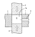
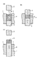
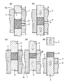
図1は、本発明に係る粉末圧縮成形金型の一実施例を示す概念説明図、図2は、この金型を用いた粉末の圧縮成形工程の工程説明図であり、図中、1は貫通孔1aを有するダイス、2は上パンチ、3は下パンチ、4は空気抜き用の排気孔、5は原料粉末、6は圧縮成形体をそれぞれ示している。
FIG. 1 is a conceptual explanatory view showing an embodiment of a powder compression molding die according to the present invention. FIG. 2 is a process explanatory view of a powder compression molding process using this die. A die having a through
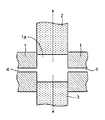
本実施形態の粉末圧縮成形金型の基本構成は、図1に示すように、貫通孔1aを有するダイス1と、貫通孔1aに内接するように挿入される上パンチ2および下パンチ3を備え、貫通孔1aの内壁と上パンチ2の下面および下パンチ3の上面とによりキャビティーCが構成される。そしてダイス1のキャビティー形成領域には、キャビティーC内の空気を抜くために、貫通孔1aの内壁から外部に通じる少なくとも一つの排気孔4が設けられている。
As shown in FIG. 1, the basic structure of the powder compression molding die of this embodiment includes a
図2(a)〜(c)は、本実施形態の粉末圧縮成形金型を用いて粉末の圧縮成形を行う際の工程説明図であり、上パンチ2を上昇させてキャビティーCの上方を開放し、ダイス1の貫通孔1aの内壁と下パンチ3で構成される空間に、成形目的とする圧縮成形体6の寸法形状に応じた量の原料粉末5を充填する〔図2(a)〕。
FIGS. 2A to 2C are process explanatory diagrams when performing powder compression molding using the powder compression molding die of the present embodiment. The
次に、上パンチ2を降下させ、好ましくは下パンチ3を上昇させることによって圧縮成形を行う〔図2(b)〕。この圧縮成形工程においては、原料粉末5の圧縮が行われる。この場合において、本実施形態の粉末圧縮成形金型にはダイス1の貫通孔1aの内壁からダイス1の外部に通じるような少なくとも一つの排気孔4が形成されているために、キャビティーCに充填された原料粉末5中に混入している空気等の気体は、原料粉末5が圧縮されるにつれて排気孔4から逐次排気される。なお、粉末圧縮成形においては、キャビティー内に充填された原料粉末を加圧するときに、上下の力が合流する部分であるニュートラルラインと呼ばれるラインが上パンチ2と下パンチ3とのほぼ中央付近に発生する。ニュートラルライン付近は、最も圧力が掛かりにくい部分であり、圧縮成形時に圧縮された空気は、ニュートラルライン付近に残りやすくなる。通常、ニュートラルライン付近に残された圧縮された空気は、成形体中に残り、密度ムラの原因となったり、均質な成形体が得られにくくなる。特に、ニュートラルライン付近における密度を低下させやすくする。本実施形態の粉末圧縮成形金型においては、キャビティーCを構成する貫通孔1aの内壁の所望の位置、具体的には、例えば、目的とする圧縮成形体にニュートラルラインを発生させる付近に排気孔4を形成することができるために、圧縮された空気等の気体を充分に排気することができる。そのために、圧縮工程後の粉末中に空気等の気体が残存することを抑制することができる。
Next, compression molding is performed by lowering the
圧縮工程後、上パンチ2をダイス1に対して相対的に上昇させる一方、下パンチ3をダイス1に対して相対的に上昇させることにより、粉末圧縮成形金型から圧縮成形体6を離型して、取り出すことができる〔図2(c)〕。離型においては、上パンチ2や下パンチ3の動きに呼応してダイス1を上下動させてもよい。
After the compression step, the
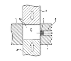
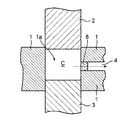
なお、圧縮工程において、排気孔4から原料粉末5が漏れ出すことを抑制するために、排気孔4のキャビティーC側の開口部近傍には、原料粉末5の通過は妨げるが、排気される気体の通過は妨げないような連通孔を有するフィルター、具体的には、原料粉末5の粒径よりも細かいサイズの網目、あるいはは細孔径の濾過部材等が設けられていることが好ましい。図3及び図4に、その一例の概念図を示す。
In the compression process, in order to prevent the
図3は、原料粉末よりも細かい網目のメッシュ7を設けた例、図4は、原料粉末より細かい連通孔を有する多孔質フィルター8を設けた例を示している。これらの例のように、排気孔4の開口部にメッシュ7や多孔質フィルター8を設けておくことにより、キャビティーCを構成する貫通孔1aの内壁に繋がる排気孔4の開口面積を大きくすることができ、そのために、圧縮工程時にキャビティーCの内部に残留する空気等の気体を効率的に排出することができる。多孔質フィルター8としては、硬質の多孔質セラミックスや多孔質超硬合金などにより形成することにより、極めて高強度なものが得られ、金属製メッシュなどを用いた場合に比べて成形可能圧力をより高くすることができる点から好ましい。
FIG. 3 shows an example in which a
なお、上記のようなフィルターを設けた場合、通気抵抗によって気体を排出しにくくなるおそれもあるが、その場合には、排気孔4に減圧ポンプ(図示せず)などの排気手段を接続設けすることにより、強制的に排気してもよい。
When the filter as described above is provided, there is a risk that gas may be difficult to exhaust due to ventilation resistance. In that case, exhaust means such as a decompression pump (not shown) are connected to the
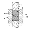
図5は、本実施形態の粉末圧縮成形金型の更に好ましい例を示す概略説明図を示す。具体的には、貫通孔1aの内壁と上パンチ2と下パンチ3との間で形成されるキャビティーCにおいて、圧縮成形される成形体6にニュートラルラインNが発生する付近における貫通孔1aの内壁に、前後・左右対称位置に、複数の排気孔4を形成した例を示している。この場合においても、各排気孔4,4のキャビティーC側の開口部付近には、上述したようなフィルターを設けることが好ましい。
FIG. 5 is a schematic explanatory view showing a more preferable example of the powder compression molding die of this embodiment. Specifically, in the cavity C formed between the inner wall of the through
図5においては、キャビティーC内の上パンチ2と下パンチ3との中間位置付近が、圧縮成形時において圧力が最も掛かりにくい部分となり、ニュートラルラインNが形成されやすい部分になり、この部分には圧縮気体が最も残り易い。この場合において、キャビティーCのニュートラルラインNの発生部に面する近傍に、例えば、前後・左右対称位置に複数の排気孔を設けることで、圧縮成形時における排気を充分に行うことができ、そのために、ニュートラルラインN付近における、抜気不足による密度の低下を抑制することができる。
In FIG. 5, the vicinity of the intermediate position between the
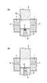
図6は、本実施形態の粉末圧縮成形金型のさらに他の例を示す概念説明図であり、ダイス1に形成された貫通孔1aの内壁に排気孔4を設けるのに加えて、下パンチ3にも上面側に貫通する排気孔4’を設けている。このように、下パンチ3側からも排気することにより、圧縮工程において、より効率的に排気を行うことができる。図6(a)の例においては、排気孔4’の開口部付近にメッシュ7を配置し、図6(b)の例においては、同じく多孔質フィルター8を配置している。同様にして、上パンチ2の下面側に排気孔4を設けることも可能であり、更に上パンチ2と下パンチ3の両方に排気孔4を設け、上下方向からも同時に排気できるようにすることにより、圧縮空気をより排気することができ、得られる圧縮成形体の密度ムラは更に少なくなって高品質の圧縮成形体を得ることができる。なお、このような形態の場合においても、必要に応じて各排気孔に吸引ポンプなどの減圧装置を接続し、積極的に排気してもよい。
FIG. 6 is a conceptual explanatory view showing still another example of the powder compression molding die of this embodiment. In addition to providing the
図7は、本実施形態の粉末圧縮成形金型のさらに他の例を示す概念説明図であり、ダイス1に形成された貫通孔1aの内壁に排気孔4を設けるのに加えて、上パンチ2と下パンチ3のいずれか一方もしくは両方(図示例では両方)を多孔質材で形成し、多孔質の連通した細孔をそのまま排気孔として利用する例を示している。このように上パンチ2または下パンチ3自体をセラミックなどの多孔質硬質材で形成すれば、各パンチの上面または下面の全面で排気を行うことができるので、より効率のよい排気が可能となる。更には、排気孔4の形成によって生じる可能性のあるパンチの強度低下も抑えることができるので、より好ましい実施態様ともいえる。
FIG. 7 is a conceptual explanatory view showing still another example of the powder compression molding die of this embodiment. In addition to providing the
本実施形態の粉末圧縮成形方法は、上述した粉末圧縮成形金型を用いて、粉末圧縮成形するものであれば、特に限定されないが、上パンチ2及び下パンチ3による粉末を圧縮する工程において、排気孔4からキャビティー内の気体が排気されすぎて、圧縮工程後にキャビティー内が減圧状態になるおそれがある。この場合においては、キャビティーCの内壁面や、上パンチ2または下パンチ3との接触面と、形成された圧縮成形体との間で真空状態が形成され、圧縮成形体が前記内壁面や接触面に張り付くことがある。このような張り付きは良好な離型を阻害するおそれがある。このような、現象を回避するために図8,図9を参照して説明される、次のような方法が挙げられる。
The powder compression molding method of the present embodiment is not particularly limited as long as it is a powder compression molding using the above-described powder compression molding die. In the step of compressing the powder by the
上述した粉末圧縮成形金型を用いて粉末圧縮成形する際に、粉末圧縮成形金型に設けられた排気孔4が給排気手段Pと接続されており、圧縮成形工程における圧縮時においては、排気孔4からキャビティーC内に残留する気体を排気し、圧縮成形工程における離型時には、キャビティーC内に空気を供給するように制御する粉末圧縮成形方法が挙げられる。
When powder compression molding is performed using the powder compression molding die described above, the
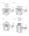
図8は、本実施形態の粉末圧縮成形方法を説明するための工程説明図であり、上パンチ2を上昇させて、ダイス1の貫通孔1aの内壁と下パンチ3とにより形成されるキャビティーC内に原料粉末5を充填し〔図8(a)〕、上パンチ2を降下させることにより原料粉末5を圧縮しながら、排気孔4から圧縮空気を排気する〔図8(b)〕。このとき排気孔4に接続されたバルブVは大気開放されている。
FIG. 8 is a process explanatory diagram for explaining the powder compression molding method of the present embodiment, in which the
圧縮成形後は、排気によりキャビティーC内は減圧されて、成形体6はキャビティーCの内壁に張り付いてしまう。張り付いた成形体6を強引に離型しようとした場合には、成形体6に無理な力がかかってクラックや割れなどを発生させる恐れがある。このような場合においては、排気孔4に接続された給排気手段Pから、離型の直前にキャビティーC内に外気を吹き込むことにより、キャビティーCの内壁に対する成形体6の張り付きを解消することができる〔図8(c)〕。このように外気を給気した後に、下パンチ3をダイス1に対して相対的に上昇させると、成形体6をキャビティーCから容易に離型することができる〔図8(d)〕。
After the compression molding, the inside of the cavity C is depressurized by the exhaust, and the molded
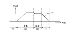
さらに、具体的には、本実施形態においては、排気孔4を介してキャビティーCと連通する給排気手段Pが設けられており、該給排気手段Pには、圧縮工程時にバルブVを開放してキャビティーC内の空気を排気する排気モードと、離型工程時にキャビティーC内に空気を供給する給気モードとに切り替える制御手段(図示せず)が設けられていることが好ましい。そして、この制御手段による排気モードと給気モードとの切替えは、図8(a)〜(d)に示した工程に応じて、例えば、図9に示すような圧力と給・排気制御によって行なう。すなわち、図9のグラフ下方の水平方向に矢印と(1)〜(4)で示している数字は、図8(a)〜(d)に示した各工程に対応しており、それぞれの工程における給排気量とキャビティーC内の圧力との関係を示している。
More specifically, in the present embodiment, an air supply / exhaust means P communicating with the cavity C through the
図9中の(1)の領域は、図8(a)で示した原料粉末5が充填されたままの状態を示しており、この状態ではキャビティーC内に全く圧力が作用しておらず、排気孔4からは給気も排気も行われない。次いで、図8(b)に示すように上パンチ2を降下させていくと、キャビティーC内の原料粉末5は徐々に圧縮され、それに伴ってキャビティーC内の圧力は上昇する。この圧縮工程において、排気孔4から内部の空気を排気することにより、原料粉末5中に残される空気を排気することができる。
The region (1) in FIG. 9 shows a state in which the
この圧縮工程においては、はじめに、上パンチ2の降下に伴う圧縮力の増加に応じて圧力は一時直線的に上昇する〔図9の(2)の領域〕。そして、原料粉末5が所定の圧縮状態に達するまでは圧縮を続けることにより、粉末の間に残された空気を排気する。その結果、キャビティーC内は減圧状態になる。
In this compression step, first, the pressure temporarily rises linearly as the compression force increases with the lowering of the upper punch 2 (region (2) in FIG. 9). The air remaining between the powders is exhausted by continuing the compression until the
そして、所定の圧縮状態に達した時には、圧縮成形体はキャビティーCの内壁や上パンチ2及び下パンチ3に減圧状態で張り付いている。従って、そのまま離型工程に移ると、上パンチ2及び下パンチ3に減圧状態で張り付いている成形体6は上下に引っ張られてクラックや割れを起こすおそれがある。そこで、離型工程〔図8(d)〕に移る前に、キャビティーC内へ空気等の気体を供給する制御を行う。これにより、減圧状態でキャビティーCの内壁面や上パンチ2及び下パンチ3に減圧状態で張り付いている成形体6の張り付きを解消することができる〔図9の領域(3)〕。そして、給気によりキャビティーC内の減圧状態を解消した後、上パンチ2を上方に退避させ、下パンチ3を上昇させることにより離型を行うことにより〔図8(d)〕、圧縮成形体に無理な力を掛けることなく成形体6を取り出すことができる〔図9の領域(4)〕。
When a predetermined compression state is reached, the compression molded body is stuck to the inner wall of the cavity C, the
このように、圧縮工程と離型工程において、排気と給気とのタイミングを制御することにより、密度ムラが少なく、且つ、割れやクラック等の欠陥の少ない圧縮成形体を効率よく得ることができる。 In this way, by controlling the timing of exhaust and air supply in the compression step and the release step, a compression molded body with less density unevenness and less defects such as cracks and cracks can be obtained efficiently. .
また、本実施形態の粉末圧縮成形方法においては、キャビティーC内に残留する気体を排気するために、ダイス1のキャビティー形成領域に、貫通孔1a内壁から外部に通じる排気孔4が形成されているような粉末圧縮成形金型を用いて圧縮成形体を成形する。このような粉末圧縮成形方法においては、排気孔4の開口部の形状が成形体6の表面に転写されるおそれがある。このような成形体6に対する開口部形状の転写は、キャビティーC内に原料粉末5を充填した後、上パンチ3及び下パンチ4により原料粉末に仮加圧することにより排気孔4からキャビティーC内に残留する気体を排気した後(仮加圧工程)と、ダイスと上パンチ3及び下パンチ4との位置関係をずらすことにより、排気孔4とキャビティーC内との連通を遮断した状態で本加圧することにより圧縮成形を行う方法により解消することができる。
Further, in the powder compression molding method of the present embodiment, in order to exhaust the gas remaining in the cavity C, the
図10(a)〜(d)はこの方法を例示する概念説明図である。まず、キャビティー内に原料粉末5を投入する〔図10(a)〕。次いで、貫通孔1aの内壁に形成された排気孔4から上・下パンチを降下・上昇させ、排気しながら原料粉末を最終の圧縮状態に達しない程度の相対的に低圧で加圧する(仮加圧工程)〔図10(b)〕。そして、仮加圧工程の後、ダイス1を上方または下方にずらして排気孔4の開口部をキャビティーから切り離す〔図10(c)〕。そして、その後、最終の圧縮状態に達するように相対的に高圧で加圧することにより成形体6を得る(本加圧工程)〔図10(d)〕。このような方法によれば、図10(d)に示すように、最終の圧縮状態に達するように相対的に高圧で加圧する本加圧の際に排気孔4の開口部はキャビティーから外れた位置にずらされているために、開口部が成形体の表面に転写されることを抑制することができる。よって、その後に上パンチ2を上方に退避させ、下パンチ3を上昇させて成形体6をダイス1の外へ押し出せば〔図10(d)〕、表面性状の良好な成形体を容易に得ることができる。
FIGS. 10A to 10D are conceptual explanatory views illustrating this method. First, the
以上、本発明に係る粉末圧縮成形金型の構成と、これを用いた粉末圧縮成形方法について代表例を示す図面によって説明してきたが、図示例は飽くまでも代表例であって本発明を限定する性質のものではない。従って、前述した本発明の構成に合致し得る範囲で更に他の変形態様を採用することも可能であり、それらはいずれも本発明の技術的範囲に包含される。 As described above, the structure of the powder compression molding die according to the present invention and the powder compression molding method using the same have been described with reference to the drawings showing typical examples. However, the illustrated examples are representative examples and the properties of the present invention are limited. Is not. Therefore, it is also possible to employ other modified embodiments within a range that can be matched with the above-described configuration of the present invention, and they are all included in the technical scope of the present invention.
1 ダイス
1a 貫通孔
2 上パンチ
3 下パンチ
4 排気孔
5 原料粉末
6 圧縮成形体
C キャビティー
7 メッシュ
8 多孔質フィルター
P 給排気手段
V 大気開放バルブ
1 Dice
1a Through
Claims (8)
前記原料粉末を圧縮する際に前記キャビティー内に残留する気体を排気するために、前記ダイスには、前記貫通孔の内壁から前記ダイスの外部に通じるような少なくとも一つの排気孔が形成されていることを特徴とする粉末圧縮成形金型。 A die having a through-hole, and an upper punch and a lower punch inserted so as to be inscribed in the through-hole, and the upper punch and the lower punch move in the vertical direction, whereby a cavity is formed in the through-hole. A powder compression molding die for holding a raw material powder in the formed cavity and compressing the raw material powder by bringing the upper punch and the lower punch close to each other to form a compression molded body Yes,
In order to exhaust the gas remaining in the cavity when the raw material powder is compressed, the die is formed with at least one exhaust hole that leads from the inner wall of the through hole to the outside of the die. A powder compression molding die characterized by
前記粉末圧縮成形金型に設けられた前記排気孔は給排気手段と接続されており、
圧縮成形工程における圧縮時には、前記排気孔から前記キャビティー内に残留する気体を排気し、圧縮成形工程における離型時には、前記キャビティー内に空気を供給するように制御することを特徴とする粉末圧縮成形方法。 Using the powder compression molding die described in any one of claims 1 to 6,
The exhaust hole provided in the powder compression mold is connected to an air supply / exhaust means,
The powder is controlled to exhaust gas remaining in the cavity from the exhaust hole during compression in the compression molding process, and to supply air into the cavity during mold release in the compression molding process. Compression molding method.
前記キャビティー内に前記原料粉末を充填した後、前記上パンチ及び前記下パンチにより前記原料粉末に仮加圧することにより前記排気孔から前記キャビティー内に残留する気体を排気する仮加圧工程と、仮加圧の後、前記ダイスと前記上パンチ及び下パンチとの位置関係をずらすことにより、前記排気孔と前記キャビティー内との連通を遮断した状態で本加圧することにより圧縮成形を行うことを特徴とする粉末圧縮成形方法。 Using the powder compression molding die described in any one of claims 1 to 6,
A pre-pressurizing step of exhausting the gas remaining in the cavity from the exhaust hole by pre-pressurizing the raw material powder by the upper punch and the lower punch after filling the raw material powder in the cavity; Then, after the temporary pressurization, compression molding is performed by shifting the positional relationship between the die, the upper punch, and the lower punch, and performing the main pressurization in a state where the communication between the exhaust hole and the cavity is blocked. A powder compression molding method.
Priority Applications (1)
| Application Number | Priority Date | Filing Date | Title |
|---|---|---|---|
| JP2008326188A JP2010142871A (en) | 2008-12-22 | 2008-12-22 | Mold and method for powder compression molding |
Applications Claiming Priority (1)
| Application Number | Priority Date | Filing Date | Title |
|---|---|---|---|
| JP2008326188A JP2010142871A (en) | 2008-12-22 | 2008-12-22 | Mold and method for powder compression molding |
Publications (1)
| Publication Number | Publication Date |
|---|---|
| JP2010142871A true JP2010142871A (en) | 2010-07-01 |
Family
ID=42563841
Family Applications (1)
| Application Number | Title | Priority Date | Filing Date |
|---|---|---|---|
| JP2008326188A Pending JP2010142871A (en) | 2008-12-22 | 2008-12-22 | Mold and method for powder compression molding |
Country Status (1)
| Country | Link |
|---|---|
| JP (1) | JP2010142871A (en) |
Cited By (3)
| Publication number | Priority date | Publication date | Assignee | Title |
|---|---|---|---|---|
| JP2012081479A (en) * | 2010-10-07 | 2012-04-26 | Nipro Corp | Tabletting machine and flange member |
| JP2012115892A (en) * | 2010-12-03 | 2012-06-21 | Kao Corp | Method for manufacturing powder compact |
| CN110839961A (en) * | 2019-12-16 | 2020-02-28 | 东莞市滨濠电子有限公司 | A heat-not-burn smoke bomb and method of making the same |
Citations (6)
| Publication number | Priority date | Publication date | Assignee | Title |
|---|---|---|---|---|
| JPS5875721U (en) * | 1981-11-13 | 1983-05-21 | 日立粉末冶金株式会社 | Mold for powder molding |
| JPS62101698U (en) * | 1985-12-17 | 1987-06-29 | ||
| JPS62230500A (en) * | 1986-04-01 | 1987-10-09 | Kyowa Hakko Kogyo Co Ltd | Mortar for compression molding |
| JPH06179098A (en) * | 1992-12-09 | 1994-06-28 | Kao Corp | Powder compression mold and method |
| JPH11170094A (en) * | 1997-10-02 | 1999-06-29 | Laeis Bucher Gmbh | Apparatus for producing molded parts and method therefor |
| JP2002172490A (en) * | 2000-12-04 | 2002-06-18 | Hiroyoshi Iwamoto | Press molding die for powdery material such as burned ash |
-
2008
- 2008-12-22 JP JP2008326188A patent/JP2010142871A/en active Pending
Patent Citations (6)
| Publication number | Priority date | Publication date | Assignee | Title |
|---|---|---|---|---|
| JPS5875721U (en) * | 1981-11-13 | 1983-05-21 | 日立粉末冶金株式会社 | Mold for powder molding |
| JPS62101698U (en) * | 1985-12-17 | 1987-06-29 | ||
| JPS62230500A (en) * | 1986-04-01 | 1987-10-09 | Kyowa Hakko Kogyo Co Ltd | Mortar for compression molding |
| JPH06179098A (en) * | 1992-12-09 | 1994-06-28 | Kao Corp | Powder compression mold and method |
| JPH11170094A (en) * | 1997-10-02 | 1999-06-29 | Laeis Bucher Gmbh | Apparatus for producing molded parts and method therefor |
| JP2002172490A (en) * | 2000-12-04 | 2002-06-18 | Hiroyoshi Iwamoto | Press molding die for powdery material such as burned ash |
Cited By (3)
| Publication number | Priority date | Publication date | Assignee | Title |
|---|---|---|---|---|
| JP2012081479A (en) * | 2010-10-07 | 2012-04-26 | Nipro Corp | Tabletting machine and flange member |
| JP2012115892A (en) * | 2010-12-03 | 2012-06-21 | Kao Corp | Method for manufacturing powder compact |
| CN110839961A (en) * | 2019-12-16 | 2020-02-28 | 东莞市滨濠电子有限公司 | A heat-not-burn smoke bomb and method of making the same |
Similar Documents
| Publication | Publication Date | Title |
|---|---|---|
| KR101652883B1 (en) | Mold forming apparatus | |
| JP6454697B2 (en) | Method and apparatus for producing a cutting insert molded body | |
| JP2008213036A (en) | Frameless mold making machine | |
| WO2005095022A1 (en) | Method and device for pouring molten metal in vacuum molding and casting | |
| CN105599111A (en) | Brick blank venting method of ceramic brick moulding machine | |
| JP3407879B2 (en) | Method and apparatus for filling and compressing molding sand | |
| KR100999439B1 (en) | Press mold for powder metallurgy and molding method using the same | |
| JP4847953B2 (en) | Method and apparatus for shaping container body | |
| CN114226691A (en) | Metal-based ceramic composite material and preparation method thereof | |
| JPH05123845A (en) | Vacuum casting apparatus and vacuum casting method | |
| CN109551612B (en) | Isostatic pressing forming method and mould for refractory sagger | |
| JPWO2021124542A5 (en) | Manufacturing method of cast products using breathable salt core | |
| US6253827B1 (en) | Method of compressing molding sand using independently controlled gas guiding pipes | |
| JP2009255112A (en) | Powder press | |
| JPS639562B2 (en) | ||
| CN105414481A (en) | Method for preforming air holes for sand tire casting | |
| EP3488945A1 (en) | Mold forming method | |
| JP2003191095A (en) | Filling method of powder molding apparatus and feeder apparatus | |
| CN212761066U (en) | Lift tube and mould | |
| JP3441065B2 (en) | Mold molding method and molding apparatus | |
| JPH11267892A (en) | Method of discharging green compact | |
| JPS5837361B2 (en) | Vacuum powder molding method | |
| JP3264420B2 (en) | Sand mold removal device | |
| JP2009000690A (en) | Foundry sand casting type mold making equipment | |
| JP4463666B2 (en) | Raw material powder filling method |
Legal Events
| Date | Code | Title | Description |
|---|---|---|---|
| A621 | Written request for application examination |
Effective date: 20111019 Free format text: JAPANESE INTERMEDIATE CODE: A621 |
|
| A711 | Notification of change in applicant |
Effective date: 20120111 Free format text: JAPANESE INTERMEDIATE CODE: A712 |
|
| A131 | Notification of reasons for refusal |
Effective date: 20130319 Free format text: JAPANESE INTERMEDIATE CODE: A131 |
|
| A02 | Decision of refusal |
Free format text: JAPANESE INTERMEDIATE CODE: A02 Effective date: 20130806 |