JP2010142872A - Vapor reflow soldering device - Google Patents
Vapor reflow soldering device Download PDFInfo
- Publication number
- JP2010142872A JP2010142872A JP2008326366A JP2008326366A JP2010142872A JP 2010142872 A JP2010142872 A JP 2010142872A JP 2008326366 A JP2008326366 A JP 2008326366A JP 2008326366 A JP2008326366 A JP 2008326366A JP 2010142872 A JP2010142872 A JP 2010142872A
- Authority
- JP
- Japan
- Prior art keywords
- carry
- heat medium
- steam
- unit
- steam tank
- Prior art date
- Legal status (The legal status is an assumption and is not a legal conclusion. Google has not performed a legal analysis and makes no representation as to the accuracy of the status listed.)
- Pending
Links
- 238000005476 soldering Methods 0.000 title claims abstract description 48
- 238000011084 recovery Methods 0.000 claims abstract description 41
- 238000010438 heat treatment Methods 0.000 claims abstract description 24
- 239000007788 liquid Substances 0.000 claims abstract description 24
- 238000001816 cooling Methods 0.000 claims description 36
- 239000002826 coolant Substances 0.000 claims description 12
- 229910000679 solder Inorganic materials 0.000 description 8
- 238000000034 method Methods 0.000 description 6
- 239000006071 cream Substances 0.000 description 4
- 238000004519 manufacturing process Methods 0.000 description 3
- 230000008018 melting Effects 0.000 description 3
- 238000002844 melting Methods 0.000 description 3
- 239000002184 metal Substances 0.000 description 3
- 230000002093 peripheral effect Effects 0.000 description 3
- 229920006395 saturated elastomer Polymers 0.000 description 3
- 239000012808 vapor phase Substances 0.000 description 3
- 238000009835 boiling Methods 0.000 description 2
- 210000000078 claw Anatomy 0.000 description 2
- 230000000694 effects Effects 0.000 description 2
- 230000003028 elevating effect Effects 0.000 description 2
- 238000001704 evaporation Methods 0.000 description 2
- 230000002542 deteriorative effect Effects 0.000 description 1
- 238000007599 discharging Methods 0.000 description 1
- 230000008020 evaporation Effects 0.000 description 1
- 239000000155 melt Substances 0.000 description 1
- 239000000203 mixture Substances 0.000 description 1
- 239000003960 organic solvent Substances 0.000 description 1
- 229910001220 stainless steel Inorganic materials 0.000 description 1
- 239000010935 stainless steel Substances 0.000 description 1
- 238000009834 vaporization Methods 0.000 description 1
- 230000008016 vaporization Effects 0.000 description 1
Images
Landscapes
- Electric Connection Of Electric Components To Printed Circuits (AREA)
Abstract
Description
本発明は、液状の熱媒体を用いてプリント基板のリフロー半田付けを行うベーパーリフロー半田付け装置に関するものである。 The present invention relates to a vapor reflow soldering apparatus that performs reflow soldering of a printed circuit board using a liquid heat medium.
従来、この種のベーパーリフロー半田付け装置(以下、「半田付け装置」という)としては、熱媒体としての不活性液体を収容した蒸気槽と、前記不活性液体を加熱する加熱部と、前記蒸気槽の上部側方から前記蒸気槽内にワークを搬入する昇降体とを備える半田付け装置が開示されている(例えば特許文献1)。 Conventionally, as this kind of vapor reflow soldering apparatus (hereinafter referred to as “soldering apparatus”), a steam tank containing an inert liquid as a heat medium, a heating unit for heating the inert liquid, and the steam A soldering device is disclosed that includes an elevating body that loads a workpiece into the steam tank from the upper side of the tank (for example, Patent Document 1).
この半田付け装置では、前記不活性液体を加熱してその液体上に飽和蒸気相を形成し、前記蒸気槽の上部側方からワークを昇降体によって蒸気槽内に搬入し、飽和蒸気相が有する気化潜熱によってワークに予め形成した半田を加熱溶融してリフロー半田付けを行う。また、当該特許文献1に係る半田付け装置は、蒸気槽の内壁に冷却コイルが設けられており、不活性液体が蒸発してなる蒸気を回収するように構成されている。このようにして半田付け装置は、冷却コイルによってワーク搬入出口部の下側領域に飽和蒸気相を保持すると共に、外部へ熱媒体が流出するのを防止するように構成されている。
しかしながら、上記特許文献1では、冷却コイルが蒸気槽の内壁に設けられているので、蒸気槽の搬入出口部の中央部分から外部へ流出する蒸気を回収することができない。そうすると、従来の半田付け装置では、高価な熱媒体が無駄に蒸気槽から流出してしまうという問題があった。
However, in
そこで、本発明は、熱媒体の流出を効果的に抑制することができる半田付け装置を提供することを目的とする。 Then, an object of this invention is to provide the soldering apparatus which can suppress the outflow of a heat medium effectively.
本発明の請求項1に係る発明は、蒸気槽と、前記蒸気槽内の下部に貯留された液体状の熱媒体と、前記熱媒体を加熱して蒸気を発生させる加熱部と、前記蒸気槽の搬入口から前記蒸気槽内にワークを搬入する搬入部とを備えるベーパーリフロー半田付け装置において、前記蒸気を凝縮して液体状に戻す熱媒体回収部が前記搬入口を塞ぐように設けられており、前記熱媒体回収部は、前記搬入部が前記ワークを搬入する動作に連動して、前記搬入口に対し出し入れ自在に設けられたことを特徴とする。
The invention according to
本発明の請求項2に係る発明は、前記熱媒体回収部は、前記搬入部が前記ワークを搬入した状態においても、前記搬入口に対し出し入れ可能であることを特徴とする。
The invention according to
本発明の請求項3に係る発明は、前記熱媒体回収部は、冷却媒体が流通する冷却パイプと、前記冷却パイプの下方に配置された受け部とを有することを特徴とする。
The invention according to
本発明の請求項1によれば、必要に応じて熱媒体回収部を移動させて、搬入口の中央部分から流出しようとする熱媒体を回収するので、熱媒体の流出を効果的に抑制することができる。 According to the first aspect of the present invention, the heat medium recovery section is moved as necessary to recover the heat medium that is about to flow out from the central portion of the carry-in port, so that the outflow of the heat medium is effectively suppressed. be able to.
本発明の請求項2によれば、蒸気槽内にワークを搬入し、当該ワークを加熱している間も、熱媒体回収部で搬入口の中央部分から流出しようとする蒸気を回収することができる。
According to
本発明の請求項3によれば、冷却パイプ内を流れる冷却媒体によって凝縮された熱媒体がワーク上に落下するのを防ぐことができるので、品質の低下を防止することができる。 According to the third aspect of the present invention, it is possible to prevent the heat medium condensed by the cooling medium flowing in the cooling pipe from falling on the work, and thus it is possible to prevent the quality from being deteriorated.
(1)全体構成
以下、図面を参照して本発明の実施形態について詳細に説明する。
(1) Overall Configuration Hereinafter, embodiments of the present invention will be described in detail with reference to the drawings.
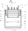
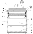
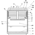
図1に示す半田付け装置1は、蒸気槽2と、前記蒸気槽2内の下部に貯留された液体状の熱媒体3と、前記熱媒体3を加熱して蒸気を発生させる加熱部4と、前記蒸気槽2の搬入口から前記蒸気槽2内にワークを搬入する搬入部5とを備える。この半田付け装置1は、加熱部4により熱媒体3を加熱して蒸気を発生し、当該蒸気によって搬入部5で搬入されたワーク6に設けられた半田を加熱溶融してリフロー半田付けを行い得るように構成されている。
A
尚、本実施形態において、ワーク6は電子部品が載置されたプリント基板である。一般的に、プリント基板に電子部品を載置する際には、まず、回路パターンに対応したステンレス鋼製のメタルマスクを用いて、電子部品が載置される回路パターンであるランド上にクリーム半田が塗布される。その後、メタルマスクを取り除くことにより、電子部品が載置されるランド上だけにクリーム半田が残るように処理される。この工程を経た後、マウンターによりプリント基板上の所定位置に電子部品が載置される。
In the present embodiment, the
蒸気槽2は、上部が開口した有底筒状の金属製容器からなり、当該上部に搬入口7が形成されている。搬入口7の周縁には、冷却部9が設けられている。冷却部9は、側壁8の内周面8aに螺旋状に設けられた固定冷却パイプ10と、当該固定冷却パイプ10の下方に配置された回収トレイ11とを有する。この固定冷却パイプ10には、図示しない冷却媒体供給装置から一定温度に保持された冷却媒体が供給されている。
The
蒸気槽2の底部2aの外側には、加熱部4が設けられている。加熱部4は、種々のものを用いることができるが、例えば内部に電熱線を張り巡らした電熱ヒータを用いることができる。この加熱部4は、蒸気槽2内に貯留された熱媒体3を蒸発させるために必要な熱量を発生させることができるものである。熱媒体3は、使用する半田の融点よりも沸点が高い不活性有機溶剤を用いる。
A
搬入部5は、ワーク6を着脱自在に保持する一対の保持部12,12と、当該保持部12に連結されたアーム部13,13とを備える。前記保持部12は、特に限定されるものではなく、例えば、爪を有し、当該爪により板状のワーク6を上下に挟んで保持することとしてもよい。前記アーム部13は、図示しない移動経路に連結されている。これにより、当該アーム部13に連結された保持部12は、搬入口7より上方の位置と、リフロー領域ARとの間を昇降する。
The carry-in
尚、移動経路は、プリント基板を製造するための複数の工程からなるプリント基板製造工程において、ワーク6を各工程間へ移動させるために張り巡らされたレールなどで構成された経路をいう。
The moving path refers to a path constituted by rails or the like that are stretched to move the
このように構成された搬入部5は、図示しないプリント基板製造工程の移動経路に沿って各工程間を移動する。また、搬入部5は、蒸気槽2に位置決めされると、保持部12を蒸気槽2内に下降させ、保持部12で固定したワーク6をリフロー領域ARに搬入し、当該ワーク6を熱媒体3の蒸気で加熱し得るように構成されている。
The carry-in
上記構成に加え、本実施形態に係る半田付け装置1は、搬入口7を塞ぐように、熱媒体回収部20が設けられている。熱媒体回収部20は、冷却媒体が流通する冷却パイプ21と、前記冷却パイプ21の下方に配置された受け部22とを有する。
In addition to the above configuration, the
この冷却パイプ21は、種々のものが考えられるが、例えば、図2に示すように、一本の管を搬入口7の一端7aと他端7bとを跨ぐように配置し、搬入口7の一端7a側において折り返してなる1組の配管23を、蒸気槽2の一対の側壁8間に複数設けることとしてもよい。この冷却パイプ21は、搬入口7の他端7b側に入口23aと出口23bとを有する。冷却パイプ21には、図示しない冷却媒体供給装置から一定温度に保持された冷却媒体が、搬入口7の他端7b側に設けられた入口23aへ供給される。
冷却媒体は、冷却パイプ21の配管23の中を搬入口7の一端7a側へ向かって流れ、さらに搬入口7の一端7a側において折り返して搬入口7の他端7b側に設けられた出口23bへと流れる。当該冷却媒体は、冷却パイプ21内を流れている間に、冷却パイプ21を介して蒸気と熱交換をすることにより、蒸気の熱を吸収する。これにより、蒸気は、凝縮され、液体状に戻る。
The cooling medium flows in the
また、冷却パイプ21の下方には、配管23毎に受け部22が設けられている。受け部22は、蒸気槽2内の下部へ連通しており、当該冷却パイプ21によって凝縮された熱媒体3を回収し、回収した当該熱媒体3を蒸気槽2内の下部へ戻すように構成されている。尚、受け部22は、冷却パイプ21との間に隙間が形成されており、冷却パイプ21内を流れる冷却媒体によって冷却されることがないように断熱されている。
A receiving
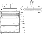
さらに半田付け装置1は、図示しない移動装置が設けられている。当該移動装置は、前記蒸気槽2の搬入口7に対し熱媒体回収部20を出し入れ自在とし得るように構成されている。すなわち、熱媒体回収部20は、搬入口7に対し入った位置、すなわち搬入口7を塞ぐように配置された位置(図2、以下「回収位置」という)と、搬入口7に対し出た位置、すなわち搬入口7の他端7bの外側へ配置され搬入口7からワーク6を搬入し得る位置(図3、以下「開放位置」という)との間を、移動装置により移動可能に構成されている。
Furthermore, the
(2)作用及び効果
次に上記構成の作用及び効果について説明する。まず、プリント基板上に電子部品を載置したワーク6を用意する。当該ワーク6は、保持部12で着脱自在に保持され、アーム部13によって移動経路に沿って各工程へ移動する。
(2) Action and Effect Next, the action and effect of the above configuration will be described. First, a
リフロー半田工程を行う半田付け装置1では、蒸気槽2内に貯留された液状の熱媒体3が加熱部4により加熱されている。熱媒体3は、その温度が沸点を超えると蒸気を発生する。発生した蒸気は、液状の熱媒体3の液面から上昇して当該液面の上方にリフロー領域ARを形成すると共に、搬入口7近傍の側壁8の内周面8aに設けられた冷却部9により凝縮され、液状に戻る。液状に戻った熱媒体3は、回収トレイ11で回収され、蒸気槽2内の下部に貯留された液状の熱媒体3に戻される。この冷却部9により、半田付け装置1は、熱媒体3が搬入口7の周縁付近から流出することを防止できる。
In the
さらに、本実施形態に係る半田付け装置1では、ワーク6が蒸気槽2へ運ばれてくる前、熱媒体回収部20が回収位置に配置されている(図2)。この熱媒体回収部20は、搬入口7の中央部分から蒸気槽2の外部へ流出しようとする蒸気を冷却パイプ21で凝縮させ、液状に戻す。液状に戻された熱媒体3は、受け部22で回収され、蒸気槽2内の下部に貯留された液状の熱媒体3に戻される。このようにして、半田付け装置1は、熱媒体回収部20が回収位置に配置されることにより、搬入口7近傍の内周面8aに設けられた冷却部9で回収されない搬入口7の中央部分を通る蒸気を回収することができるので、熱媒体3の流出を効果的に抑制することができる。
Furthermore, in the
また、半田付け装置1は、ワーク6が蒸気槽2の搬入口7へ運ばれてくるのに連動して、熱媒体回収部20を開放位置へ移動させる(図3)。そうすると、蒸気槽2は、それまで熱媒体回収部20によって塞がれていた搬入口7が開放される。これにより、搬入部5は、ワーク6を蒸気槽2内へ降下させることが可能となる。
Also, the
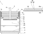
搬入口7に位置決めされた状態で、搬入部5は、保持部12に固定したワーク6を搬入口7の上方からリフロー領域ARへ搬入する(図4)。リフロー領域ARへ搬入されたワーク6は、蒸気によって加熱される。同時にワーク6に設けられたクリーム半田が加熱溶融される。
While being positioned at the carry-in
一方、ワーク6がリフロー領域ARに搬入されると同時に、熱媒体回収部20が開放位置から熱回収位置へ復帰する(図1及び図5)。これにより、熱媒体回収部20は、ワーク6を蒸気槽2内で加熱している間、搬入口7の中央部分から外部へ流出しようとする蒸気を回収する。
On the other hand, simultaneously with the
このように熱媒体回収部20は、搬入部5がワーク6をリフロー領域ARに搬入した際、回収位置に移動し得るように構成されている。これにより、半田付け装置1は、蒸気槽2内において、蒸気によりワーク6を加熱している間も、搬入口7から外部へ流出しようとする蒸気を熱媒体回収部20で回収することができる。従って、半田付け装置1は、高価な熱媒体3が蒸気槽2から流出するのをより確実に抑制することができる。
As described above, the heat
所定時間経過してクリーム半田の加熱溶融が終了すると、半田付け装置1は、ワーク6を排出するに先立って、熱媒体回収部20を開放位置へ移動させる(図4)。これにより、蒸気槽2は、それまで熱媒体回収部20によって塞がれていた搬入口7が開放される。
When heating and melting of the cream solder is completed after a predetermined time has elapsed, the
次いで、搬入部7は、ワーク6をリフロー領域ARから搬入口7の上方へ排出する(図3)。ここで、ワーク6は冷却され、溶融されたクリーム半田が固着することにより、半田付け工程が終了する。
Next, the carry-in
次いで、半田付け装置1は、搬入部5が移動経路に沿って次工程へと移動するのに連動して、熱媒体回収部20を回収位置へ移動させる(図2)。
Next, the
上記したように、半田付け装置1は、ワーク6を蒸気槽2内のリフロー領域ARに搬入する際と、リフロー領域ARから排出する際には、熱媒体回収部20を開放位置に配置するように構成し、ワーク6が蒸気槽2に運ばれてくる前、ワーク6を蒸気槽2に搬入して蒸気で加熱している間、及び、ワーク6を蒸気槽2から排出した後のそれぞれにおいて、熱媒体回収部20を回収位置に配置するように構成した。これにより、半田付け装置1は、搬入部5と、熱媒体回収部20との干渉を防ぎながら、搬入口7の中央部分から流出しようとする蒸気を回収することができる。このように、半田付け装置1は、必要に応じて熱媒体回収部20を移動させて、熱媒体3の流出を効果的に抑制することができる。
As described above, when the
また、前記熱媒体回収部20は、冷却パイプ21の下方に配置された受け部22を有することにより、冷却パイプ21内を流れる冷却媒体によって凝縮された熱媒体3がワーク6上に落下するのを防ぐことができる。従って、半田付け装置1は、製品の品質を低下させずに、熱媒体3を効率的に回収して、蒸気槽2から熱媒体3が流出することを抑制できる。
Further, the heat
また、半田付け装置1は、冷却パイプ21を有する熱媒体回収部20で熱媒体3の流出を抑制するように構成していることにより、環状冷却パイプ10と協働して、蒸気槽2内の温度をより一定に保持することができると共に、構造を簡素化できるので、コスト低減を実現することができる。
In addition, the
本発明は上記した実施形態に限定されるものではなく、本発明の趣旨の範囲内で適宜変更することが可能である。 The present invention is not limited to the above-described embodiment, and can be appropriately changed within the scope of the gist of the present invention.
例えば、冷却パイプ21は、一本の管を搬入口7を塞ぐように配置し、搬入口7の一端7a側において折り返してなる1組の配管23を、蒸気槽2の一対の側壁8間に複数設ける場合について説明したが、本発明はこれに限らず、冷却パイプ21は、搬入口7を塞ぐように
蛇行状や螺旋状に形成した配管を用いることとしてもよい。
For example, in the cooling
1 半田付け装置(ベーパーリフロー半田付け装置)
2 蒸気槽
3 熱媒体
4 加熱部
5 搬入部
6 ワーク
7 搬入口
20 熱媒体回収部
21 冷却パイプ
22 受け部
1 Soldering device (vapor reflow soldering device)
2
20 Heat recovery unit
21 Cooling pipe
22 Receiver
Claims (3)
前記蒸気槽内の下部に貯留された液体状の熱媒体と、
前記熱媒体を加熱して蒸気を発生させる加熱部と、
前記蒸気槽の搬入口から前記蒸気槽内にワークを搬入する搬入部と
を備えるベーパーリフロー半田付け装置において、
前記蒸気を凝縮して液体状に戻す熱媒体回収部が前記搬入口を塞ぐように設けられており、
前記熱媒体回収部は、前記搬入部が前記ワークを搬入する動作に連動して、前記搬入口に対し出し入れ自在に設けられた
ことを特徴とするベーパーリフロー半田付け装置。 A steam tank;
A liquid heat medium stored in the lower part of the steam tank;
A heating unit for heating the heat medium to generate steam;
In a vapor reflow soldering apparatus comprising a carry-in part for carrying a work into the steam tank from a carry-in port of the steam tank,
A heat medium recovery unit that condenses the vapor and returns it to a liquid state is provided so as to block the carry-in entrance,
The vapor reflow soldering apparatus, wherein the heat medium recovery unit is provided so as to be freely inserted into and withdrawn from the carry-in port in conjunction with an operation in which the carry-in unit carries in the work.
Priority Applications (1)
| Application Number | Priority Date | Filing Date | Title |
|---|---|---|---|
| JP2008326366A JP2010142872A (en) | 2008-12-22 | 2008-12-22 | Vapor reflow soldering device |
Applications Claiming Priority (1)
| Application Number | Priority Date | Filing Date | Title |
|---|---|---|---|
| JP2008326366A JP2010142872A (en) | 2008-12-22 | 2008-12-22 | Vapor reflow soldering device |
Publications (1)
| Publication Number | Publication Date |
|---|---|
| JP2010142872A true JP2010142872A (en) | 2010-07-01 |
Family
ID=42563842
Family Applications (1)
| Application Number | Title | Priority Date | Filing Date |
|---|---|---|---|
| JP2008326366A Pending JP2010142872A (en) | 2008-12-22 | 2008-12-22 | Vapor reflow soldering device |
Country Status (1)
| Country | Link |
|---|---|
| JP (1) | JP2010142872A (en) |
Citations (2)
| Publication number | Priority date | Publication date | Assignee | Title |
|---|---|---|---|---|
| JPS62148085A (en) * | 1985-12-23 | 1987-07-02 | Hitachi Techno Eng Co Ltd | Paper reflow soldering equipment |
| JPH0385161U (en) * | 1989-12-19 | 1991-08-28 |
-
2008
- 2008-12-22 JP JP2008326366A patent/JP2010142872A/en active Pending
Patent Citations (2)
| Publication number | Priority date | Publication date | Assignee | Title |
|---|---|---|---|---|
| JPS62148085A (en) * | 1985-12-23 | 1987-07-02 | Hitachi Techno Eng Co Ltd | Paper reflow soldering equipment |
| JPH0385161U (en) * | 1989-12-19 | 1991-08-28 |
Similar Documents
| Publication | Publication Date | Title |
|---|---|---|
| CA2688385C (en) | Method and apparatus for removing contaminants from a reflow apparatus | |
| TW201529217A (en) | Flux management system and method for a wave solder machine | |
| US4022371A (en) | Vapor bonding method | |
| JP2010087464A (en) | Method for dismantling electrical apparatus | |
| CN1004680B (en) | Soldering apparatus for articles | |
| JPH0343935B2 (en) | ||
| JP2004327816A (en) | Reflow soldering method and apparatus | |
| JP6352519B1 (en) | Method and apparatus for cleaning object to be cleaned | |
| JP2017006855A (en) | Cleaning liquid distillation regeneration device, parts cleaning device, and cleaning liquid distillation regeneration method | |
| JP2018122298A (en) | Cleaning liquid distillation regeneration device, parts cleaning device, and cleaning liquid distillation regeneration method | |
| JP2017213542A (en) | Steam generating apparatus and steam cleaning apparatus | |
| JP2009302341A (en) | Soldering device and soldering method | |
| US20140048103A1 (en) | Method and apparatus for continuous separation of cleaning solvent from rinse fluid in a dual-solvent vapor degreasing system | |
| JP2000334402A (en) | Vacuum vapor cleaning device | |
| JP4921229B2 (en) | Cleaning device | |
| JP2549211B2 (en) | Vapor soldering equipment | |
| JP4402403B2 (en) | Work cleaning device | |
| JP4525611B2 (en) | Reflow soldering method and apparatus | |
| JP6668166B2 (en) | Fluorine-containing organic solvent recovery device and substrate processing device | |
| JPH07246459A (en) | Filtering method in vapor phase soldering device | |
| JP2023154140A (en) | Solvent regeneration equipment | |
| JPH0220352B2 (en) | ||
| JPH01107965A (en) | Filtering device for solvent for vapor phase soldering | |
| JPS6031295A (en) | Vapor soldering method and device therefor | |
| JPS63313663A (en) | Vapor phase soldering device |
Legal Events
| Date | Code | Title | Description |
|---|---|---|---|
| A621 | Written request for application examination |
Effective date: 20110908 Free format text: JAPANESE INTERMEDIATE CODE: A621 |
|
| A977 | Report on retrieval |
Effective date: 20121220 Free format text: JAPANESE INTERMEDIATE CODE: A971007 |
|
| A02 | Decision of refusal |
Effective date: 20130507 Free format text: JAPANESE INTERMEDIATE CODE: A02 |