JP2010143069A - Ink-jet recording device - Google Patents
Ink-jet recording device Download PDFInfo
- Publication number
- JP2010143069A JP2010143069A JP2008322550A JP2008322550A JP2010143069A JP 2010143069 A JP2010143069 A JP 2010143069A JP 2008322550 A JP2008322550 A JP 2008322550A JP 2008322550 A JP2008322550 A JP 2008322550A JP 2010143069 A JP2010143069 A JP 2010143069A
- Authority
- JP
- Japan
- Prior art keywords
- ink
- waste
- waste ink
- valve
- recording head
- Prior art date
- Legal status (The legal status is an assumption and is not a legal conclusion. Google has not performed a legal analysis and makes no representation as to the accuracy of the status listed.)
- Pending
Links
Images
Landscapes
- Ink Jet (AREA)
Abstract
【課題】記録用インクの供給と廃インクの回収とが同時に行え、廃インクの回収を待たなくてもインクタンクの交換が可能なインクジェット記録装置を提供すること。
【解決手段】廃インクの回収経路内に廃インク溜めを設けない構成において、同一のインクタンク内にインク用と廃インク用のそれぞれの袋体を設けて、それら各袋体と繋がる各インクの経路内に弁とポンプをそれぞれ設ける。更にインク経路では記録ヘッドと弁との間に、インクを溜めることが可能なポンプと繋がった加圧室を設ける。
【選択図】図1To provide an ink jet recording apparatus that can supply recording ink and collect waste ink at the same time, and can replace an ink tank without waiting for collection of waste ink.
In a configuration in which a waste ink reservoir is not provided in a waste ink collection path, ink and waste ink bags are provided in the same ink tank, and each ink connected to each bag is provided. Provide a valve and a pump in the path. Further, in the ink path, a pressurizing chamber connected to a pump capable of storing ink is provided between the recording head and the valve.
[Selection] Figure 1
Description
本発明はインクを吐出することで記録をおこなうインクジェット記録装置およびそれと同等のものに関するもので、特に廃インク処理に関するものである。 The present invention relates to an ink jet recording apparatus that performs recording by discharging ink and the like, and more particularly to waste ink processing.
従来、インクジェット記録装置(以下、単に記録装置ともいう)は、記録媒体(用紙等)上を横切って往復運動するキャリッジに搭載されたインクジェット記録ヘッド(以下、単に記録ヘッドともいう)を用いることが多い。記録ヘッドが記録媒体上を横切って運動するに伴い、制御部が記録ヘッドの吐出部に設けられた記録素子を起動して、記録媒体上にイメージまたは文字を形成するため吐出ノズルからインク滴を吐出する。記録ヘッドへのインクの補給はインクタンクから行われる。 Conventionally, an ink jet recording apparatus (hereinafter also simply referred to as a recording apparatus) uses an ink jet recording head (hereinafter also simply referred to as a recording head) mounted on a carriage that reciprocates across a recording medium (such as paper). Many. As the recording head moves across the recording medium, the control unit activates a recording element provided in the ejection unit of the recording head to eject ink droplets from the ejection nozzles to form an image or characters on the recording medium. Discharge. Ink is supplied to the recording head from the ink tank.
インクジェット記録装置においては、記録ヘッドのインク吐出部に、紙粉やゴミ等の異物の付着や、吐出部のインクが乾燥して粘度が増すあるいは固着することによる吐出不良、更には吐出不能になる恐れがある。このような問題を防止する手段として、非記録時にインク吐出部を、ゴム状の弾性部材で形成されたキャップにより密閉する構成が採られている。しかし、非記録時にはインク吐出部を密閉するキャッピング状態での対処だけでは、長時間キャッピング状態で放置した際、インク吐出部の表面層のインクが増粘する事があり、始めの数回の吐出はインクを完全に吐出することができない。 In an ink jet recording apparatus, foreign matter such as paper dust or dust adheres to the ink discharge portion of the recording head, or the ink in the discharge portion dries and increases in viscosity or becomes stuck, resulting in discharge failure and further failure to discharge. There is a fear. As a means for preventing such a problem, a configuration is adopted in which the ink discharge portion is sealed with a cap formed of a rubber-like elastic member during non-recording. However, when the ink is not recorded, the ink ejection part is sealed only in the capping state, and the ink on the surface layer of the ink ejection part may thicken when left in the capping state for a long time. Cannot eject ink completely.
そのため記録前にまず、記録に寄与しないインクを吐出することで、インク吐出部表面層のインクの状態を正常状態に復帰させる、いわゆる予備吐出が行われている。また更に、予備吐出でインク吐出部表面層のインク状態が正常に復帰しない場合にはポンプ等によって強制的にインク吐出部表面層のインクを吸引あるいは加圧することも行われている。このようなインクの吸引あるいは加圧により、キャッピンク状態でインクを排出させてインク吐出部のインクを正常に復帰させる回復動作を行っている。また、記録動作中にも、インクの吐出によって次第に記録ヘッドの吐出部(吐出口面)にインクが付着して、これが吐出不良の原因となることがあるため、所定のタイミングで記録ヘッドの予備吐出動作を行っている。上記のような予備吐出動作や吸引動作により吐出口より排出されたインクは、廃インクとして装置内で処理される。また、縁無し印刷時に記録媒体の外側へ吐出されたインクも、同様に廃インクとして処理される。 For this reason, so-called preliminary ejection is performed to restore the ink state of the surface layer of the ink ejection portion to a normal state by ejecting ink that does not contribute to recording first before recording. Further, when the ink state of the ink discharge portion surface layer does not return to normal during preliminary discharge, the ink on the ink discharge portion surface layer is forcibly sucked or pressurized by a pump or the like. By such suction or pressurization of the ink, a recovery operation is performed in which the ink is discharged in the cap pink state and the ink in the ink discharge unit is returned to normal. In addition, even during the recording operation, ink may gradually adhere to the ejection portion (ejection port surface) of the recording head due to ink ejection, which may cause ejection failure. Discharging operation is performed. The ink discharged from the discharge port by the preliminary discharge operation or the suction operation as described above is processed in the apparatus as waste ink. Also, ink ejected to the outside of the recording medium during borderless printing is similarly processed as waste ink.
記録装置内には、このような廃インクを収納するための廃インク回収装置が付設されている。この廃インク回収装置をインクタンクと一体化させて、インクタンクに廃インクを回収する構成がある。たとえば特許文献1においては、インク袋と廃インク吸収体をもつ複数個のインクタンクを搭載した記録装置が開示されている。また、特許文献2においては回復系により負圧吸引された廃インクが、ブラックインクとして再利用される記録装置が開示されている。
A waste ink collecting device for storing such waste ink is attached in the recording apparatus. There is a configuration in which the waste ink collecting device is integrated with an ink tank to collect waste ink in the ink tank. For example,
しかしながら、従来例による廃インクの回収は、回復系の吸引圧力をそのまま、廃インクの吸収体などに吸収させて排出していたために、空気が混入した廃インクがインクタンクに戻ることになっていた。そのため、排出先は気液交換のため、大気開放状態にする必要があり大量に回収した場合には、大気開放口から廃インク漏れなどを発生させていた。 However, the waste ink recovery according to the conventional example is that the suction pressure of the recovery system is directly absorbed by the waste ink absorber and discharged, so that the waste ink mixed with air returns to the ink tank. It was. For this reason, the discharge destination needs to be opened to the atmosphere for gas-liquid exchange, and when a large amount is collected, waste ink leaks from the opening of the atmosphere.
記録ヘッドへのインクの供給は、昨今、柔軟フィルムなどにより形状可変に形成されたインク袋を加圧したり、またはインク袋と記録ヘッドの間に位置する供給流路に加減圧ポンプを持つことで供給したりする場合が多い。記録装置内には、予備吐出や吸引動作による複数箇所からの廃インクを収集し一時溜め置きする廃インク溜めをもち、廃インク溜めに収集された廃インクをある程度まとめてインクタンクに回収する構成がある。インクタンクに収集するには専用の廃インク容器が必要であり、密閉され収縮自在の廃インク容器の周囲を負圧状態にすることで記録装置内の廃インク溜めからインクタンク内の廃インク容器に廃インクを回収することが可能になる。 Ink supply to the recording head has recently been achieved by pressurizing an ink bag that is variably formed by a flexible film or the like, or by having a pressure increasing / decreasing pump in a supply channel located between the ink bag and the recording head. Often supplied. The recording device has a waste ink reservoir that collects and temporarily stores waste ink from multiple locations by preliminary ejection and suction operations, and collects the waste ink collected in the waste ink reservoir to some extent and collects it in an ink tank There is. In order to collect in the ink tank, a dedicated waste ink container is required, and the waste ink container in the ink tank from the waste ink reservoir in the recording device is made by putting a negative pressure around the sealed and shrinkable waste ink container. It becomes possible to collect the waste ink.
しかし、インクタンクの中にインク袋と廃インク容器とを持つ場合、廃インクの回収時の廃インク容器の周囲の負圧状態で、供給流路間の加減圧ポンプによるインクの供給が阻害されることがある。そのため、記録用インクの供給と廃インクの回収とが同時に行えないという不具合があった。さらに、記録中に同時に廃インクの回収ができないために、記録装置本体側から廃インクの回収指示が出ている場合には、記録終了後、廃インクの回収を待ってからでなければインクタンクの交換ができなかった。 However, if the ink tank has an ink bag and a waste ink container, the supply of ink by the pressure-reducing pump between the supply channels is hindered by the negative pressure around the waste ink container when collecting the waste ink. Sometimes. For this reason, there is a problem that the supply of the recording ink and the recovery of the waste ink cannot be performed at the same time. In addition, because waste ink cannot be collected at the same time during recording, if an instruction for collecting waste ink is issued from the recording device main body, the ink tank must be waited for the waste ink to be collected after the recording is finished. Could not be replaced.
よって本発明は、記録用インクの供給と廃インクの回収とが同時に行え、廃インクの回収を待たなくてもインクタンクの交換が可能なインクジェット記録装置を提供することを目的とする。 Therefore, an object of the present invention is to provide an ink jet recording apparatus that can supply recording ink and collect waste ink at the same time, and can replace the ink tank without waiting for the collection of waste ink.
そのため本発明のインクジェット記録装置は、インクを吐出する記録ヘッドと、インクタンクから記録ヘッドへと前記インクを供給することが可能なインク供給路と、前記記録ヘッドから吐出された廃インクを前記インクタンクへと回収するための廃インク流路と、を備えたインクジェット記録装置において、前記インク供給路には該インク供給路を開閉することが可能な第1の弁が設けられており、該第1の弁と前記記録ヘッドとの間には、第1のポンプによって内部圧力の加減圧が可能な加圧室が設けられており、前記廃インク流路には、該廃インク流路を開閉することが可能な第2の弁が設けられていることを特徴とする。
Therefore, the ink jet recording apparatus of the present invention includes a recording head for discharging ink, an ink supply path through which the ink can be supplied from an ink tank to the recording head, and waste ink discharged from the recording head as the ink. In an ink jet recording apparatus provided with a waste ink flow path for collecting into a tank, the ink supply path is provided with a first valve capable of opening and closing the ink supply path. A pressure chamber capable of increasing and decreasing the internal pressure by a first pump is provided between the
本発明のインクジェット記録装置は、インク供給路に、インク供給路を開閉可能な第1の弁を備えている。更に本発明のインクジェット記録装置は、その第1の弁と記録ヘッドとの間には、第1のポンプによって内部圧力の加減圧が可能な加圧室を備え、廃インク流路には、廃インク流路を開閉可能な第2の弁を備えている。これによって、記録用インクの供給と廃インクの回収とが同時に行え、廃インクの回収を待たなくてもインクタンクの交換が可能なインクジェット記録装置を実現することができた。 The ink jet recording apparatus of the present invention includes a first valve that can open and close the ink supply path in the ink supply path. Furthermore, the ink jet recording apparatus of the present invention is provided with a pressurizing chamber capable of increasing / decreasing the internal pressure by the first pump between the first valve and the recording head, and the waste ink flow path is disposed of the waste ink flow path. A second valve capable of opening and closing the ink flow path is provided. As a result, it is possible to realize an ink jet recording apparatus that can supply the recording ink and collect the waste ink at the same time, and can replace the ink tank without waiting for the collection of the waste ink.
(第1の実施形態)
以下、図面を参照して本発明の第1の実施形態を説明する。
本発明はこれらの実施形態のみに限らず、これらをさらに組み合わせることや、この特許請求の範囲に記載された本発明の概念に包含されるあらゆる変更や修正が可能であり、従って本発明の精神に帰属する他の技術にも当然応用することができる。
(First embodiment)
Hereinafter, a first embodiment of the present invention will be described with reference to the drawings.
The present invention is not limited to these embodiments, and further combinations thereof, and any changes and modifications included in the concept of the present invention described in the claims can be made. Naturally, it can also be applied to other technologies belonging to.
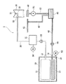
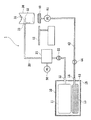
図1は、本実施形態におけるインクジェット記録装置(以下、単に記録装置ともいう)1におけるインクの流れが分かるように示した模式図である。インクジェット記録装置1においては、インクタンク10から供給されたインクが、インク供給管(インク供給路)20を経由して記録ヘッド30にインクが供給される。記録ヘッド30は、記録媒体搬送方向に対して直交する方向に往復動作することで、記録媒体(不図示)に印刷(以下、記録ともいう)を行う。記録ヘッド30から吐出されたインクで、印刷に使われなかったインク(以下、廃インク)は、吸引キャップ40や予備吐口41にまず集められ、廃インク回収管(廃インク流路)42を経由して廃インク溜め43に一旦保存される。廃インク溜め43に蓄えられた廃インクは、適宜、廃インク溜め43から廃インク回収管42を経由してインクタンク10に回収される。
FIG. 1 is a schematic view showing the flow of ink in an ink jet recording apparatus (hereinafter also simply referred to as a recording apparatus) 1 according to the present embodiment. In the ink
インクタンク10は、第1の液体収容部であるところの形状可変に形成されたインク袋体11とインク供給口を密閉するゴム栓12、第2の液体収容部である形状可変に形成された廃インク袋体13と廃インク回収口を密閉するゴム栓14を備えている。またインクタンク10は、第2の圧力発生源である減圧ポンプ(第2のポンプ)52と密閉接続するためのゴム栓15、およびインク袋体11と廃インク袋体13を収容する固定容積空間をもつ収納ケース16を備えている。インク供給管20の一端は、先端が鋭利な中空管であるインク針がゴム栓12に差し込まれることでインク供給管20へのインクの導出を可能にしている。同様に、廃インク回収管42の一端は先端が鋭利な中空管であるインク針がゴム栓14に差し込まれることで廃インク回収管42から廃インクの回収を可能にしている。各インク針の各ゴム栓への差込と同時に第2の圧力発生源である減圧ポンプ52が収納ケース16と接続される。減圧ポンプ52は、ケース内部を全域に渡って減圧することができる。
The
インクタンク10から供給されたインクは、インク供給管20、第3の液体収容部である加圧室21、供給弁(第1の弁)22、第1の圧力発生源である加減圧ポンプ(第1のポンプ)50からなる供給路を経由して記録ヘッド30に供給される。供給路を開閉する開閉弁である供給弁22は、インクタンク10と加圧室21の間に設置され、必要に応じて開閉する。加圧室21にはある一定量の以下のインクを溜め込むことが出来る。加減圧ポンプ50は、加圧室21に対して作用し、加圧室21を減圧することでインクタンク10からインクを加圧室に溜めおきし、加圧室21を加圧することで加圧室21に溜め込まれたインクを記録ヘッド30に供給することができる。
The ink supplied from the
記録ヘッド30は、その壁の一部が可とう膜31により構成されている。可とう膜31は、インクの消費に伴う記録ヘッド30内部の圧力変化に応じて伸縮動作を行う。可とう膜31の伸縮動作は、可とう膜31に接続されたアーム32に伝えられ、さらにはアーム32の可とう膜31とは反対側の先端に接続された弁33に伝えられる。弁33はインク供給管20と記録ヘッド30との接続部を塞いでおり、上記のような仕組みによって、インクの消費に伴って開閉される。
A part of the wall of the
廃インクは、記録ヘッド30の信頼性を保つために不可避的に発生するものである。廃インクには、吸引キャップ40に廃棄されるものと、予備吐出口41に廃棄されるものとに大別することができる。吸引キャップ40は、印刷領域から外れた場所に位置し、非印刷時に記録ヘッド30のインク吐出面を保護・保湿するために使われる他、印刷開始前や印刷中の予備吐を受けたり、記録ヘッド30の吐出面を吸引回復したりするときに使われる。予備吐出によって吸引キャップ40の表面に溜まった廃インクは、吸引ポンプ51により回収され、廃インク回収管42を経由して廃インク溜め43に蓄えられる。また、吸引回復が行われるときは、記録ヘッド30のインク吐出面と吸引キャップ40が密閉し、吸引ポンプ51が動作することで記録ヘッド30からインクが吸い出され、廃インク回収管42を経由して廃インク溜め43に蓄えられる。予備吐出口41は、印刷領域から外れた吸引キャップ40とは反対側に設置される場合や、印刷領域の適当な場所に設置される場合がある。予備吐出口41に溜まった廃インクは、重力によって廃インク回収管42を経由して廃インク溜め43に蓄えられる。
Waste ink is inevitably generated in order to maintain the reliability of the
廃インク溜め43の底部、もしくは底部近傍は、廃インク回収管42によってインクタンク10と接続されている。廃インク回収管の途中に廃インク弁(第2の弁)44が設けられている。減圧ポンプ52によってインクタンク10の内部が減圧されると、廃インク溜め43に蓄えられた廃インクが廃インク回収管42へ流出し、最終的に廃インク袋体13に回収される。
The bottom of the
次に、記録動作におけるインクの流れと各部の動きを説明する。 Next, the flow of ink and the movement of each part in the recording operation will be described.
(初期充填動作)
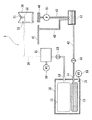
図2は、記録装置1の供給弁22を開いた状態を示した図である。インクタンク10からインク供給管20へのインク導出は、加減圧ポンプ50を使用して加圧室51内を減圧することによって行う。供給弁22を開放し、加減圧ポンプ50を減圧方向に作動させると、インクタンク10から導出されたインクは加圧室21に蓄えられる。加圧室21に所定の閾値までインクが蓄えられたら減圧を止め、図1のように供給弁22を閉にする。次に、加減圧ポンプ50を加圧方向に作動させ、加圧室21に蓄えられたインクを所定の圧力まで加圧する。しかし、記録ヘッド30内の弁33がインク供給管20を塞ぐ力は、加圧されたインクの所定の圧力よりも大きいため、弁33が開いてインク供給管20と記録ヘッド30が連通するということはない。そのため、吸引キャップ40を記録ヘッド30と密閉させ、吸引ポンプ51を作動させることで、記録ヘッド30の内部を減圧する必要がある。これによって弁33が開き、記録ヘッド30にインクを供給することができる。所定量のインクが記録ヘッド30内に供給されたら吸引ポンプ51を止め、吸引キャップ40を記録ヘッド30から分離する。その結果、記録ヘッド30内の負圧値との釣り合いによって弁33が閉じるまでインクが供給された後、インクの供給は停止する。
(Initial filling operation)
FIG. 2 is a view showing a state in which the
(印刷中のインク供給動作)
印刷によって記録ヘッド30内のインクが消費されると、記録ヘッド30内の負圧が高まる。その結果、弁33が開くので、加圧室21で加圧されたインクが記録ヘッド30に供給され、記録ヘッド30内の負圧との釣り合いによって弁33は閉じられる。印刷中は上記の動作の繰り返しによって、加圧室21に蓄えられたインクが記録ヘッド30に供給される。加圧室21に蓄えられたインク量が所定の閾値以下になると、インクタンク10から加圧室21にインクを供給する動作が行われる。すなわち、加減圧ポンプ50の加圧動作を停止し、加圧室21の加圧が解除された段階で供給弁22を開き、次に加減圧ポンプ50を減圧方向に作動させることで、インクタンク10内のインクが加圧室21に供給される。このとき、記録ヘッド30内の弁33は閉じたままであるので、記録ヘッド30内のインクが加圧室21に供給されることはない。加圧室21内のインクが所定量に達した場合、もしくは加圧室21が減圧されてから所定の時間が経過した場合、供給弁22を閉じ、加減圧ポンプ50を加圧方向に作動させることで、加圧室21へのインク供給を終了する。
(Ink supply operation during printing)
When ink in the
(廃インク回収動作)
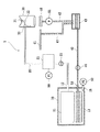
図3は、記録装置1の廃インク弁44を開いた状態を示した図である。廃インク溜め43に蓄えられた廃インク量が所定の閾値以上になると、廃インクをインクタンク10に回収する動作が行われる。廃インク弁44を開き、減圧ポンプ52を作動させることで、廃インク溜め43に蓄えられた廃インクを廃インク回収管42に流出させ、最終的に廃インク袋体13内に回収する。先に減圧ポンプ52を作動させ、インクタンク10内が十分に減圧されてから廃インク弁44を開いても良い。廃インク溜め43内の廃インクが所定量以下になったら、あるいは廃インク回収動作が始まってから所定時間の後、廃インク弁44を閉める。さらに減圧ポンプ52を大気開放することでインクタンク10内の負圧を解消し、廃インク回収動作を終了する。
(Waste ink recovery operation)
FIG. 3 is a view showing a state in which the
(印刷中の回収動作)
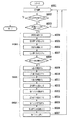
図4は、印字中のインクの供給および廃インク回収動作のフローチャートである。以下、フローチャートに沿って印字中の廃インク回収動作について説明する。なお、フローチャートにおいてステップS001からステップS007までは記録ヘッド30へのインク供給動作であり、既に説明しているためここでは説明を省略し、ステップS008以降の廃インク回収動作についてを説明する。
(Recovery operation during printing)
FIG. 4 is a flowchart of ink supply and waste ink recovery operations during printing. Hereinafter, the waste ink collecting operation during printing will be described with reference to the flowchart. In the flowchart, steps S001 to S007 are ink supply operations to the
ステップS008で廃インク溜め43内の廃インクが閾値以上であるかを確認する。閾値以下であれば、ステップS001に戻り印字を継続するが、閾値以上の場合、ステップS009へと移行する。ステップS009からステップS012までは、上記と同様の記録ヘッド30へのインク供給を行う。ステップS012で加減圧ポンプ50を加圧にして、ステップS013で、廃インク弁44を開放する。その後、ステップS014で減圧ポンプ52を負圧にしてインクタンク10内を減圧することで廃インク溜め43内の廃インクをインクタンク10の廃インク袋体13内へと導く。減圧ポンプ52によりインクタンク10内は負圧状態になるが、供給弁22は閉塞状態のため、加圧室内の加圧値が影響を受けることなく、記録ヘッド30へのインク供給をおこなうことができる。そしてステップS015へと移行して、廃インク弁44を閉じて、ステップS016で減圧ポンプ52を大気開放する。そして、ステップS017で廃インク回収動作を終了する。
In step S008, it is confirmed whether the waste ink in the
このように、同一のインクタンク内にインク用と廃インク用のそれぞれの袋体を設けて、それら各袋体と繋がる各インク(インクおよび廃インク)の経路内に弁とポンプをそれぞれ設ける。更にインク経路では記録ヘッドと弁との間に、インクを溜めることが可能なポンプと繋がった加圧室を設ける。これによって、記録用インクの供給と廃インクの回収とが同時に行うことができ、記録中に廃インクの回収を行うことで、廃インクの回収に要する時間を待たなくてもインクタンクの交換が可能なインクジェット記録装置を実現することができた。 As described above, the ink and waste ink bags are provided in the same ink tank, and the valves and pumps are provided in the paths of the inks (ink and waste ink) connected to the bags. Further, in the ink path, a pressurizing chamber connected to a pump capable of storing ink is provided between the recording head and the valve. As a result, the recording ink can be supplied and the waste ink can be collected at the same time. By collecting the waste ink during recording, the ink tank can be replaced without waiting for the time required to collect the waste ink. A possible ink jet recording apparatus could be realized.
(第2の実施形態)
以下、図5を参照して本発明の第2の実施形態を説明する。なお、本実施形態の基本的な構成は第1の実施形態と同様であるため、以下では、本実施形態の特徴的な構成についてのみ説明する。
(Second Embodiment)
Hereinafter, a second embodiment of the present invention will be described with reference to FIG. Since the basic configuration of this embodiment is the same as that of the first embodiment, only the characteristic configuration of this embodiment will be described below.
図5は、本実施形態のインクジェット記録装置におけるインクの流れが分かるように示した模式図である。本実施形態は、第1の実施形態のように廃インク溜めを設けていない構成である。インクタンク10内は大気開放口53においてインク袋体11および廃インク袋体13の形状に関わらず、大気圧が保たれる構成になっている。また、吸引ポンプ51の排出口に廃インク回収管42の一端が接続され、他端が廃インク袋体13に接続されている。
FIG. 5 is a schematic diagram showing the ink flow in the ink jet recording apparatus of this embodiment. This embodiment has a configuration in which no waste ink reservoir is provided as in the first embodiment. In the
印字中記録ヘッド30は吸引キャップ40に予備吐出を行う。吸引キャップ40から予備吐出による廃インクを吸引する前には、加減圧ポンプ50によりインク袋体11から加圧室21へのインクの供給をおこなう。すなわち、供給弁22を開放し加減圧ポンプ50を負圧にすることで加圧室21にはインクが供給される。その後、供給弁22を閉塞して、記録ヘッド30の予備吐出により発生した吸引キャップ40内の廃インクを吸引ポンプ51によって吸引し、直接廃インク回収管42を通って、廃インク袋体13に回収される。
During printing, the
廃インク袋体13への廃インクの回収により、収納ケース16の中ではインク袋体11は多少の圧力を受ける。このときも、供給弁22が閉状態であれば、加圧室21内のインクが圧力の変動を受けることなく、安定した印字を続けることが可能になる。
By collecting the waste ink into the waste
このように、廃インクの回収経路内に廃インク溜めを設けない構成において、同一のインクタンク内にインク用と廃インク用のそれぞれの袋体を設けて、それら各袋体と繋がる各インク(インクおよび廃インク)の経路内に弁とポンプをそれぞれ設ける。更にインク経路では記録ヘッドと弁との間に、インクを溜めることが可能なポンプと繋がった加圧室を設ける。これによって、記録用インクの供給と廃インクの回収とが同時に行うことができ、記録中に廃インクの回収を行うことで、廃インクの回収に要する時間を待たなくてもインクタンクの交換が可能なインクジェット記録装置を実現することができた。 As described above, in the configuration in which the waste ink reservoir is not provided in the waste ink collection path, each ink body (for each ink and waste ink is provided in the same ink tank, and each ink ( In the path of ink and waste ink), a valve and a pump are provided. Further, in the ink path, a pressurizing chamber connected to a pump capable of storing ink is provided between the recording head and the valve. As a result, the recording ink can be supplied and the waste ink can be collected at the same time. By collecting the waste ink during recording, the ink tank can be replaced without waiting for the time required to collect the waste ink. A possible ink jet recording apparatus could be realized.
10 インクタンク
11 インク袋体
13 廃インク袋体
20 インク供給管
21 加圧室
22 供給弁
30 記録ヘッド
33 弁
40 吸引キャップ
42 廃インク回収管
44 廃インク弁
50 加減圧ポンプ
51 吸引ポンプ
52 減圧ポンプ
DESCRIPTION OF
Claims (5)
前記インク供給路には該インク供給路を開閉することが可能な第1の弁が設けられており、
該第1の弁と前記記録ヘッドとの間には、第1のポンプによって内部の圧力の加減圧が可能な加圧室が設けられており、
前記廃インク流路には、該廃インク流路を開閉することが可能な第2の弁が設けられていることを特徴とするインクジェット記録装置。 A recording head for discharging ink, an ink supply path through which the ink can be supplied from the ink tank to the recording head, and a waste ink for collecting the waste ink discharged from the recording head into the ink tank An ink jet recording apparatus comprising a flow path,
The ink supply path is provided with a first valve capable of opening and closing the ink supply path,
Between the first valve and the recording head, there is provided a pressurizing chamber capable of increasing / decreasing the internal pressure by a first pump,
The inkjet recording apparatus, wherein the waste ink channel is provided with a second valve capable of opening and closing the waste ink channel.
Priority Applications (1)
| Application Number | Priority Date | Filing Date | Title |
|---|---|---|---|
| JP2008322550A JP2010143069A (en) | 2008-12-18 | 2008-12-18 | Ink-jet recording device |
Applications Claiming Priority (1)
| Application Number | Priority Date | Filing Date | Title |
|---|---|---|---|
| JP2008322550A JP2010143069A (en) | 2008-12-18 | 2008-12-18 | Ink-jet recording device |
Publications (1)
| Publication Number | Publication Date |
|---|---|
| JP2010143069A true JP2010143069A (en) | 2010-07-01 |
Family
ID=42563998
Family Applications (1)
| Application Number | Title | Priority Date | Filing Date |
|---|---|---|---|
| JP2008322550A Pending JP2010143069A (en) | 2008-12-18 | 2008-12-18 | Ink-jet recording device |
Country Status (1)
| Country | Link |
|---|---|
| JP (1) | JP2010143069A (en) |
Cited By (4)
| Publication number | Priority date | Publication date | Assignee | Title |
|---|---|---|---|---|
| JP2013188964A (en) * | 2012-03-14 | 2013-09-26 | Seiko Epson Corp | Liquid ejecting apparatus |
| CN104768765A (en) * | 2012-09-26 | 2015-07-08 | 船井电机株式会社 | Expandable waste ink receptacle for micro-fluid supply item |
| US9244381B2 (en) | 2011-08-19 | 2016-01-26 | Hewlett-Packard Development Company, L.P. | Toner container |
| CN108349256A (en) * | 2015-12-22 | 2018-07-31 | 惠普发展公司,有限责任合伙企业 | Printing-fluid box for pumping printing-fluid system |
-
2008
- 2008-12-18 JP JP2008322550A patent/JP2010143069A/en active Pending
Cited By (6)
| Publication number | Priority date | Publication date | Assignee | Title |
|---|---|---|---|---|
| US9244381B2 (en) | 2011-08-19 | 2016-01-26 | Hewlett-Packard Development Company, L.P. | Toner container |
| US9703243B2 (en) | 2011-08-19 | 2017-07-11 | Hewlett-Packard Development Company, L.P. | Toner Cartridge |
| JP2013188964A (en) * | 2012-03-14 | 2013-09-26 | Seiko Epson Corp | Liquid ejecting apparatus |
| CN104768765A (en) * | 2012-09-26 | 2015-07-08 | 船井电机株式会社 | Expandable waste ink receptacle for micro-fluid supply item |
| CN108349256A (en) * | 2015-12-22 | 2018-07-31 | 惠普发展公司,有限责任合伙企业 | Printing-fluid box for pumping printing-fluid system |
| US10442205B2 (en) | 2015-12-22 | 2019-10-15 | Hewlett-Packard Development Company, L.P. | Printing fluid cartridge for a pumped printing fluid system |
Similar Documents
| Publication | Publication Date | Title |
|---|---|---|
| JP5676858B2 (en) | Recording device | |
| JP2001232816A (en) | Ink jet recording apparatus and ink supply method | |
| JP5381296B2 (en) | Ink cartridge and image forming apparatus | |
| JP2010099856A (en) | Waste ink collecting apparatus and recording device | |
| US6814432B2 (en) | Inkjet recording device and ink supplying device employed thereby | |
| JP5523221B2 (en) | Pressure purge device for ink jet recording apparatus | |
| EP2962855B1 (en) | Liquid accommodating container, liquid ejecting device and liquid introducing method | |
| JP2009023251A (en) | Inkjet recording device | |
| JP2003094681A (en) | Inkjet printing machine | |
| JP2010143010A (en) | Inkjet recording apparatus | |
| JP2010089379A (en) | Inkjet recording device | |
| JP2010105195A (en) | Inkjet recorder | |
| JP4256184B2 (en) | Liquid jet recording apparatus and ink filling method | |
| JPH10202910A (en) | Method for eliminating bubbles in ink supply path of ink jet recording apparatus and ink jet recording apparatus suitable for the method | |
| JP3259481B2 (en) | Ink tank and manufacturing method thereof | |
| JP5630323B2 (en) | Shipment method of image forming apparatus | |
| JP2010143070A (en) | Ink filling method | |
| CN1224517C (en) | Ink filling method and device for inkjet cartridge | |
| JP4590480B2 (en) | Inkjet device maintenance method | |
| JP2012218173A (en) | Inkjet recorder | |
| JP2010125686A (en) | Inkjet recording device | |
| JP2010142971A (en) | Inkjet recorder and ink recovery method | |
| JP2004066463A (en) | Liquid drop ejection recorder and its ink filling method | |
| JP2002264358A (en) | Inkjet image forming equipment | |
| JPH0899416A (en) | Operation method of pump for inkjet device |
Legal Events
| Date | Code | Title | Description |
|---|---|---|---|
| RD02 | Notification of acceptance of power of attorney |
Effective date: 20101106 Free format text: JAPANESE INTERMEDIATE CODE: A7422 |