JP2010143319A - Bumper mounting device - Google Patents
Bumper mounting device Download PDFInfo
- Publication number
- JP2010143319A JP2010143319A JP2008321010A JP2008321010A JP2010143319A JP 2010143319 A JP2010143319 A JP 2010143319A JP 2008321010 A JP2008321010 A JP 2008321010A JP 2008321010 A JP2008321010 A JP 2008321010A JP 2010143319 A JP2010143319 A JP 2010143319A
- Authority
- JP
- Japan
- Prior art keywords
- bumper
- hole
- fixture
- mounting device
- bumper support
- Prior art date
- Legal status (The legal status is an assumption and is not a legal conclusion. Google has not performed a legal analysis and makes no representation as to the accuracy of the status listed.)
- Pending
Links
- 238000003780 insertion Methods 0.000 claims abstract description 57
- 230000037431 insertion Effects 0.000 claims abstract description 57
- 238000006073 displacement reaction Methods 0.000 claims description 13
- 210000000078 claw Anatomy 0.000 description 4
- 238000000034 method Methods 0.000 description 3
- 238000003466 welding Methods 0.000 description 3
Images


Classifications
-
- B—PERFORMING OPERATIONS; TRANSPORTING
- B60—VEHICLES IN GENERAL
- B60R—VEHICLES, VEHICLE FITTINGS, OR VEHICLE PARTS, NOT OTHERWISE PROVIDED FOR
- B60R19/00—Wheel guards; Radiator guards, e.g. grilles; Obstruction removers; Fittings damping bouncing force in collisions
- B60R19/02—Bumpers, i.e. impact receiving or absorbing members for protecting vehicles or fending off blows from other vehicles or objects
- B60R19/24—Arrangements for mounting bumpers on vehicles
- B60R2019/245—Arrangements for mounting bumpers on vehicles with adjusting means to compensate manufacturing tolerances, e.g. between bumper and energy absorbers
Landscapes
- Engineering & Computer Science (AREA)
- Mechanical Engineering (AREA)
- Body Structure For Vehicles (AREA)
- Connection Of Plates (AREA)
Abstract
Description
本発明は、車両のボデーとバンパの間に配置されて、バンパをボデーに取り付けるためのバンパ取付装置に関する。 The present invention relates to a bumper attachment device that is disposed between a body and a bumper of a vehicle and attaches the bumper to the body.
特開2004−114715号公報に、バンパ取付装置の一例が開示されている。この公報に開示されているように、バンパは、例えば、車両のボデーに予め固定されたバンパ取付装置に固定され、或いは、よく知られているように、車両のボデーに予め溶接する等して設けたスタッドに固定される。
しかしながら、ボデーにおけるバンパ取付装置の取付位置やスタッドの溶接位置にバラツキが生じることがあり、バラツキが生じた状態でバンパを取り付けてしまうと、ボデーに対するバンパの配置がずれる、換言すれば、ボデー11とバンパ13の見切り寸法が(車両上下方向の隙)や面位置(車両左右方向の位置)において適合しなくなる危険がある。
Japanese Patent Application Laid-Open No. 2004-114715 discloses an example of a bumper mounting device. As disclosed in this publication, the bumper is fixed to a bumper mounting device that is fixed in advance to the vehicle body, or is welded to the vehicle body as is well known. It is fixed to the provided stud.
However, there may be variations in the mounting position of the bumper mounting device and the welding position of the stud on the body, and if the bumper is mounted in a state where the variation has occurred, the arrangement of the bumper with respect to the body will be deviated. There is a risk that the parting dimension of the
本願発明は、このような従来技術における問題点を解決するためになされたものであり、バンパを取り付ける際の、ボデーとバンパの隙等の管理を容易にするバンパ取付装置を提供することを目的とする。 The present invention has been made to solve such problems in the prior art, and an object of the present invention is to provide a bumper mounting device that facilitates management of a gap between a body and a bumper when the bumper is mounted. And
本発明の一つの態様によれば、車両のボデーとバンパの間に配置して、前記バンパを前記ボデーに対して取り付けるためのバンパ取付装置であって、前記バンパを支持することができるバンパ支持体と、前記ボデーに固定された固定部に回転可能に取り付けられる取付具と、を備え、前記取付具は、前記バンパ支持体の貫通穴に挿通される挿通部を有し、該挿通部を前記貫通穴に挿通させて前記バンパ支持体を支持しつつ前記挿通部を前記貫通穴に対して回転させることにより、前記取付具の一部を前記バンパ支持体の一部と当接させ、該当接を通じて、前記バンパ支持体の前記ボデーに対する位置を調整することを特徴とするバンパ取付装置が提供される。 According to one aspect of the present invention, a bumper mounting device that is disposed between a vehicle body and a bumper and mounts the bumper to the body, the bumper support capable of supporting the bumper. And a fixture that is rotatably attached to a fixed portion that is fixed to the body, and the fixture has an insertion portion that is inserted into a through hole of the bumper support, and the insertion portion A part of the fixture is brought into contact with a part of the bumper support by rotating the insertion part with respect to the through hole while inserting the through hole to support the bumper support. A bumper mounting device is provided that adjusts the position of the bumper support relative to the body through contact.
上記装置において、前記バンパ支持体に少なくとも2つの貫通穴を設け、各貫通穴に前記取付具を挿通させてもよい。
また、前記挿通部の外面に該挿通部を拡径する弾性舌片部を設け、該弾性舌片部を前記貫通穴に押し当てることにより前記取付具を前記バンパ支持体に仮止めしてもよい。
更に、前記空隙の上部に、前記バンパ支持体の外部に突出して、前記ボデーと衝突し得る突部が設けられていてもよい。
In the above apparatus, at least two through holes may be provided in the bumper support, and the fixture may be inserted into each through hole.
Further, an elastic tongue piece for expanding the diameter of the insertion portion is provided on the outer surface of the insertion portion, and the attachment tool is temporarily fixed to the bumper support by pressing the elastic tongue piece against the through hole. Good.
Furthermore, a protrusion that protrudes to the outside of the bumper support and may collide with the body may be provided above the gap.
また、上記装置において、前記挿通部の外面の一部に該挿通部を拡径する厚肉部を設け、前記貫通穴を、前記厚肉部を有する前記挿通部と略同径・同形状とするとともに、前記貫通穴の上方の一部に、薄肉の弾性変位部を挟んで空隙を設け、前記挿通部を前記貫通穴に挿通させた状態で前記挿通部を前記貫通穴に対して回転させることにより、前記厚肉部と前記弾性変位部を当接させ、該当接を通じて前記弾性変位部を前記取付具の径方向において前記厚肉部から遠ざかる方向に押しやって、前記バンパ支持体の前記ボデーに対する位置を調整してもよい。 Further, in the above apparatus, a thick portion for expanding the insertion portion is provided on a part of the outer surface of the insertion portion, and the through hole has substantially the same diameter and shape as the insertion portion having the thick portion. In addition, a gap is provided in a part above the through hole with a thin elastic displacement portion interposed therebetween, and the insertion portion is rotated with respect to the through hole in a state where the insertion portion is inserted into the through hole. Thus, the thick portion and the elastic displacement portion are brought into contact with each other, and the elastic displacement portion is pushed in a radial direction of the fixture in a direction away from the thick portion through the contact, and the body of the bumper support body is pushed. The position relative to may be adjusted.
上記装置において、前記挿通部の周囲に設けたフランジに前記バンパ支持体側に突出する突出部を設け、前記バンパ支持体の貫通穴の周囲に前記取付具側に突出する対応突出部を設け、前記挿通部を前記貫通穴に挿通させた状態で前記挿通部を前記貫通穴に対して回転させることにより、前記突出部と前記対応突出部を当接させ、該当接を通じて前記バンパ支持体を前記ボデー側に押しやって、前記バンパ支持体の前記ボデーに対する位置を調整するようにしてもよい。
上記装置において、前記バンパ支持体の対応突出部はスロープ状とされていてもよい。
また、上記装置において、前記弾性舌片部と前記厚肉部は、前記取付具の回転方向に関して約90度離されていてもよい。
In the above device, a flange provided around the insertion portion is provided with a protruding portion protruding toward the bumper support, and a corresponding protrusion protruding toward the fixture is provided around a through hole of the bumper support. By rotating the insertion portion with respect to the through hole in a state where the insertion portion is inserted into the through hole, the protrusion and the corresponding protrusion are brought into contact with each other, and the bumper support body is attached to the body through the contact. The position of the bumper support relative to the body may be adjusted by pushing to the side.
In the above apparatus, the corresponding protrusion of the bumper support may have a slope shape.
Moreover, the said apparatus WHEREIN: The said elastic tongue piece part and the said thick part may be separated about 90 degree | times regarding the rotation direction of the said fixture.
また、前記挿通部に前記取付具の回転軸に向かって径方向に延びる固定手段を設け、該固定手段を利用して、前記固定部に前記取付具を回転可能に取り付けるようにしてもよい。
また、上記装置において、前記固定手段は、前記取付具の回転方向に関して約180度離された一対の弾性係止片と、前記取付具の回転方向に関して約180度離された一対の固定片から成り、前記一対の弾性係止片と前記一対の固定片は、前記取付具の回転方向に関して約90度離されていてもよい。
Further, a fixing means extending in a radial direction toward the rotation axis of the fixture may be provided in the insertion portion, and the fixture may be rotatably attached to the fixing portion using the fixing means.
Further, in the above apparatus, the fixing means includes a pair of elastic locking pieces separated by about 180 degrees with respect to the rotation direction of the fixture and a pair of fixed pieces separated by about 180 degrees with respect to the rotation direction of the fixture. The pair of elastic locking pieces and the pair of fixed pieces may be separated by about 90 degrees with respect to the rotation direction of the fixture.
本願発明によれば、スタッドの位置や高さのバラツキに影響されることなく、バンパ取付装置のボデーに対する位置を最適なものとすることができる。 According to the present invention, the position of the bumper mounting device with respect to the body can be optimized without being affected by variations in the position and height of the stud.
以下、添付図面を参照しつつ、本発明によるバンパ取付装置の好適な一つの実施形態について説明する。 Hereinafter, a preferred embodiment of a bumper mounting device according to the present invention will be described with reference to the accompanying drawings.
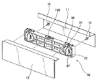
図1に、本発明によるバンパ取付装置、即ち、バンパ取付用のリテーナ10を、車両のボデー11やバンパ13とともに斜視図で示す。
FIG. 1 is a perspective view of a bumper mounting device according to the present invention, that is, a
バンパ13の取付時に、本装置10は、車両のボデー11とバンパ13の間に配置される。更に言えば、本装置10は、ボデー11に予め溶接されたスタッド(固定部)12を利用してボデー11に対して固定され、ボデー11に固定された本装置10に対して、バンパ13が取り付けられる。
明らかなように、バンパ13は、本装置10を介して、ボデー11に間接的に固定されるだけである。
故に、本装置10を、ボデー11に対して適当に位置決めすることにより、本装置10に固定されるバンパ13を、ボデー11に対して適当に位置決めできる。
The
As can be seen, the
Therefore, the
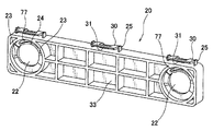
本装置10をボデー11に対して適当に位置決めするため、本装置10は、主に、2つの構成部品を備える。一方は、図2に示した取付具、即ち、ノブ60、他方は、図3に示したバンパ支持体、即ち、リテーナ本体20である。図2、図3に、これらの構成部品を個品図として斜視図で示す。尚、図2においては、取付具60を、その正面斜視図(図2のa))と裏面斜視図(図2のb))で示している。
In order to properly position the
取付具60は、略円筒状の挿通部73と、この挿通部73の周囲を取り囲むように設けた円環状のフランジ66、更に、フランジ66の前方に延びるツマミ67を有する。挿通部73は、20のノブ取付穴(貫通穴)22に挿通される部分、ツマミ67は、挿通部73を20に対して回転させるための部分である。
The
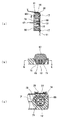
本装置10をボデー11に取り付けるにあたり、先ず、本装置10を、図4に示す状態、即ち、仮組立状態とする。図4のa)は、仮組立状態にある本装置10の正面図、b)は、その上面図、c)は、a)におけるA−A線断面図、d)は、a)におけるB−B線断面図、e)は、d)におけるC−C線断面図である。
In attaching the
仮組立状態とするため、バンパ支持体20に設けた2つの貫通穴22のそれぞれに、取付具60を挿通する。挿通部73の円筒形外面には、挿通部73を拡径する仮組立ツメ(弾性舌片部)72が設けてある。バンパ支持体20の貫通穴22に挿通部73を挿通させたとき、弾性舌片部72が貫通穴22に押し当てられ、取付具60はバンパ支持体20に対して仮止めされる。この結果、取付具60は、バンパ支持体20に関して、図4に示す位置で止まる、つまり、仮組立状態とされる。仮組立状態は、取付具60(挿通部73)をバンパ支持体20に対して回転させたときに解除され、本組立状態とされる。
In order to obtain a temporary assembly state, the
挿通部73の円筒形外面には、更に、挿通部73を拡径する車両高さ方向調整用当て部(厚肉部)70が設けてある。厚肉部70は、弾性舌片部72から、取付具60の回転方向に関して約90度離された位置にあり、挿通部73を貫通穴22に挿通させた状態で、図4に示す仮組立状態にある挿通部73を貫通穴22に対して回転させることにより、厚肉部70とバンパ支持体20の車両上下方向調整弾性片(弾性変位部)74を当接させ、この当接を通じて、バンパ支持体20のボデー11に対する位置を調整することができるようになっている。
The cylindrical outer surface of the
挿通部73を取り囲むフランジ66の一方の面、換言すれば、挿通部73を設けた側に、ボデー11への固定時にバンパ支持体20側に突出し得るリブ(突出部)69が設けられている。突出部69は、挿通部73を挟んだ同軸対向位置に1つずつ、計2つ設けてある。挿通部73を貫通穴22に挿通させた状態で、図4に示す仮組立状態にある挿通部73を貫通穴22に対して回転させることにより、これらの突出部69を、バンパ支持体20の車両左右方向調整スロープ(対応突出部)23と当接させ、この当接を通じて、バンパ支持体20をボデー11側に押しやって、バンパ支持体20のボデー11に対する位置を調整することができるようになっている。尚、突出部69は、必ずしもフランジ66に設ける必要はなく、取付具60の挿通部73の周囲にバンパ支持体20側に突出した状態で設けられていればよい。
On one surface of the
挿通部73の内部に、ボデー11に固定されたスタッド12に取付具60を回転可能に取り付けるための固定手段68、71が設けられている。これらの固定手段68、71は、取付具60の回転軸に向かって径方向に延びている。固定手段86、71は2タイプに分類される。一方は、取付具60の回転方向に関して約180度離した状態で同軸対向位置に設けた一対のスタッド固定ツメ(弾性係止片)68、もう一方は、同様の方法で設けた一対のスタッド保持リブ(固定片)71である。これら一対の弾性係止片68と一対の固定片71は、取付具60の回転方向に関して約90度離されている。固定片71は、スタッド12に対する取付具60の位置をある程度規制する役割を果たし、弾性係止片68は、固定片71によって位置規制された取付具60をスタッド12に弾性係止させる機能を有する。これらを利用して、取付具60をボデー11に固定されたスタッド12に回転可能に弾性的に取り付けることができる。尚、本装置10がボデー11の固定部12に一旦取り付けられると、スタッドのフランジ15が、弾性係止片68の係止面78と当接し、これによって、取付具60の抜けが防止される。スタッドのフランジ15との当接を良好に保つため、係止面78に、スタッドの形状に対応した窪み79を設けてもよい(図4のe)参照)。
Fixing means 68 and 71 for rotatably attaching the
バンパ支持体20は、所定の厚みを有する矩形の枠体として形成される。強度を増すため、枠体の中心付近に複数の部屋33が形成してある。枠体の両端には、取付具60を取り付けるための貫通穴22が1つずつ、計2つ設けられている。これらの貫通穴22には、取付具60の一部73が挿通される。
The
貫通穴22は、厚肉部70を有する取付具60の挿通部73と、略同径・同形状とされている。故に、この貫通穴22に、挿通部73を挿通させることができる。更に、貫通穴22の上方の一部に、薄肉の弾性変位部74を挟んで空隙77が設けられている。挿通部73を貫通穴22に挿通させた状態で、図4に示す仮組立状態にある挿通部73を貫通穴22に対して回転させることにより、厚肉部70を空隙77の下方に移動させて、厚肉部70とバンパ支持体20の弾性変位部74を当接させ、この当接を通じて、バンパ支持体20のボデー11に対する位置を調整することができる。
The through
貫通穴22の周囲には、取付具60の側に突出する車両左右方向調整スロープ(対応突出部)23が設けられている。スロープ23は、取付具60の突出部69に対応する部材である。挿通部73を貫通穴22に挿通させた状態で、図4に示す仮組立状態にある挿通部73を貫通穴22に対して回転させることにより、突出部69を、スロープ23と当接させ、この当接を通じて、バンパ支持体20のボデー11に対する位置を調整することができる。尚、本実施形態のように対応突出部23をスロープ状とした場合には、バンパ支持体20に徐々に力を加えるようにして微調整することができる。
Around the through
図5、図6を参照して、本装置の作用を説明する。図5、図6は、仮組立状態と本組立状態をそれぞれ示す。ここで、図5のa)は、図4のc)に対応する断面図、図5のb)は、図4のd)に対応する断面図、更に、図5のc)は、図4のe)に対応する断面図であって、図5のb)のD−D線断面図である。同様に、図6のa)は、図4のc)に対応する断面図、図6のb)は、図4のd)に対応する断面図、更に、図6のc)は、図4のe)に対応する断面図であって、図6のb)のE−E線断面図である。尚、図6のa)、b)、c)の断面図は、それぞれ、図5のa)、b)、c)に対応している。 The operation of the present apparatus will be described with reference to FIGS. 5 and 6 show a temporary assembly state and a main assembly state, respectively. Here, a) in FIG. 5 is a cross-sectional view corresponding to c) in FIG. 4, b) in FIG. 5 is a cross-sectional view corresponding to d) in FIG. 4, and c) in FIG. It is sectional drawing corresponding to e) of FIG., Comprising: It is the DD sectional view taken on the line of b) of FIG. Similarly, a) of FIG. 6 is a cross-sectional view corresponding to c) of FIG. 4, b) of FIG. 6 is a cross-sectional view corresponding to d) of FIG. 4, and c) of FIG. It is sectional drawing corresponding to e) of FIG., Comprising: It is the EE sectional view taken on the line of b) of FIG. Note that the cross-sectional views of a), b), and c) in FIG. 6 correspond to a), b), and c) in FIG. 5, respectively.
図5、図6を比較検討することにより、仮組立状態と本組立状態における位置状態が明らかになる。図5に示す仮組立状態にある取付具60及びバンパ支持体20は、取付具60(挿通部73)をバンパ支持体20に対して図示矢印「ア」方向に回転させることによって、図6に示す本組立状態、即ち、バンパ支持体20のボデー11に対する位置を調整しつつ、バンパ支持体20をボデー11へ完全に固定した状態とすることができる。
By comparing FIG. 5 and FIG. 6, the position state in the temporary assembly state and the final assembly state becomes clear. The
例えば、ボデー11に固定されたスタッド12の溶接位置精度にバラツキがある場合、図5のa)によく示されるように、仮組立状態においては、ボデー11とバンパ13の見切り寸法が車両上下方向の隙(図5のa)に「イ」で示す))や、面位置、即ち、車両左右方向の位置(図5のa)に「ウ」で示す)において適合しないことがある。
For example, when the welding position accuracy of the
しかしながら、図5に示すように、本装置10を、弾性係止片68、固定片71を利用して、ボデー11の固定部12に仮取付した後、取付具60を「ア」方向に回転させることにより、車両左右方向においては、突出部69をスロープ23と当接させ、この当接を通じて、バンパ支持体20をボデー11の車両左右方向管理面16側に押し付けることができ、また、車両上下方向においては、厚肉部70を空隙77の下方に移動させ、厚肉部70とバンパ支持体20の弾性変位部74を当接させて、この当接を通じて、弾性変位部74を取付具60の径方向において厚肉部70から遠ざかる方向に押しやり、異径とした取付具60の外径70によってバンパ支持体20を車両上方に押し上げて、バンパ支持体20をボデー11の車両上下方向管理面17側に押し付けることができる。尚、空隙77の上部には、バンパ支持体20の外部に突出して、ボデー11と衝突し得る高さ方向当てリブ(突部)25が設けられており、ボデー11は常にこの突部25に衝突した状態とされる。更に、ボデー11と突部25が衝突した後も、空隙77や弾性変位部74が変形することから、取付具60を更に回転させることが可能とされており、これにより、スタッド12の位置バラツキを吸収して一定に調整することができる。このように、本装置10においては、バンパ支持体20がボデー11に、車両左右方向或いは車両上下方向において押し付けることができる構造となっており、従って、スタッド12の位置や高さのバラツキに影響されることなく、バンパ支持体20のボデー11に対する位置を最適なものとすることができる。以上の本発明によれば、溶接位置のバラツキを吸収し、バンパ13とボデー11の見切り、即ち、ボデー11とバンパ13との隙を常に一定に管理することができる。
However, as shown in FIG. 5, the
最後に、図7の断面図を参照して、バンパ13の取付方法について説明する。図7は、本装置10を、図5のa)や図6のa)と同様の方法で示したものである。本装置10をボデー11の所望とする位置に取付けた後、バンパ13を支持することができる。例えば、バンパ支持体20の上側面に設けた弾性片30の先端に、下方に延びる係止ツメ31を設け、この係止ツメ31を、バンパ13に設けた係止穴14に係合させることによって、バンパ13をバンパ支持体20に容易に取り付け、支持することができる。
Finally, a method for attaching the
10 バンパ取付装置
11 ボデー
12 固定部
13 バンパ
16 車両左右方向管理面
17 車両上下方向管理面
20 バンパ支持体
22 貫通穴
23 対応突出部
25 突部
60 取付具
66 フランジ
67 ツマミ
68 弾性係止片
69 突出部
70 厚肉部
71 固定片
72 弾性舌片部
73 挿通部
74 弾性変位部
77 空隙
DESCRIPTION OF
Claims (10)
前記バンパを支持することができるバンパ支持体と、
前記ボデーに固定された固定部に回転可能に取り付けられる取付具と、を備え、
前記取付具は、前記バンパ支持体の貫通穴に挿通される挿通部を有し、該挿通部を前記貫通穴に挿通させて前記バンパ支持体を支持しつつ前記挿通部を前記貫通穴に対して回転させることにより、前記取付具の一部を前記バンパ支持体の一部と当接させ、該当接を通じて、前記バンパ支持体の前記ボデーに対する位置を調整することを特徴とするバンパ取付装置。 A bumper mounting device that is disposed between a vehicle body and a bumper and mounts the bumper to the body,
A bumper support that can support the bumper;
A fixture that is rotatably attached to a fixed portion fixed to the body,
The fixture has an insertion portion that is inserted into the through hole of the bumper support body, and the insertion portion is inserted into the through hole while the insertion portion is inserted into the through hole to support the bumper support body. The bumper mounting device is characterized in that a part of the mounting tool is brought into contact with a part of the bumper support by rotating and the position of the bumper support relative to the body is adjusted through the contact.
前記挿通部を前記貫通穴に挿通させた状態で前記挿通部を前記貫通穴に対して回転させることにより、前記厚肉部と前記弾性変位部を当接させ、該当接を通じて前記弾性変位部を前記取付具の径方向において前記厚肉部から遠ざかる方向に押しやって、前記バンパ支持体の前記ボデーに対する位置を調整する請求項1乃至3のいずれかに記載のバンパ取付装置。 A thick portion for expanding the insertion portion is provided on a part of the outer surface of the insertion portion, and the through hole has substantially the same diameter and shape as the insertion portion having the thick portion, and the through hole A gap is provided in a part of the upper part of the wall with a thin elastic displacement part interposed therebetween,
By rotating the insertion part with respect to the through hole in a state where the insertion part is inserted into the through hole, the thick part and the elastic displacement part are brought into contact with each other, and the elastic displacement part is moved through the corresponding contact. 4. The bumper mounting device according to claim 1, wherein the bumper mounting device adjusts a position of the bumper support relative to the body by pushing in a direction away from the thick portion in a radial direction of the mounting tool. 5.
前記バンパ支持体の貫通穴の周囲に前記取付具側に突出する対応突出部を設け、
前記挿通部を前記貫通穴に挿通させた状態で前記挿通部を前記貫通穴に対して回転させることにより、前記突出部と前記対応突出部を当接させ、該当接を通じて前記バンパ支持体を前記ボデー側に押しやって、前記バンパ支持体の前記ボデーに対する位置を調整する請求項1乃至5のいずれかに記載のバンパ取付装置。 Providing a protrusion that protrudes toward the bumper support on the flange provided around the insertion part,
Provide a corresponding protrusion that protrudes toward the fixture around the through hole of the bumper support,
By rotating the insertion portion with respect to the through hole in a state where the insertion portion is inserted into the through hole, the protrusion and the corresponding protrusion are brought into contact with each other, and the bumper support is moved through the contact. The bumper mounting device according to any one of claims 1 to 5, wherein the bumper mounting device adjusts a position of the bumper support relative to the body by pushing toward a body side.
Priority Applications (2)
| Application Number | Priority Date | Filing Date | Title |
|---|---|---|---|
| JP2008321010A JP2010143319A (en) | 2008-12-17 | 2008-12-17 | Bumper mounting device |
| US12/639,127 US8226133B2 (en) | 2008-12-17 | 2009-12-16 | Bumper attachment device |
Applications Claiming Priority (1)
| Application Number | Priority Date | Filing Date | Title |
|---|---|---|---|
| JP2008321010A JP2010143319A (en) | 2008-12-17 | 2008-12-17 | Bumper mounting device |
Publications (1)
| Publication Number | Publication Date |
|---|---|
| JP2010143319A true JP2010143319A (en) | 2010-07-01 |
Family
ID=42353567
Family Applications (1)
| Application Number | Title | Priority Date | Filing Date |
|---|---|---|---|
| JP2008321010A Pending JP2010143319A (en) | 2008-12-17 | 2008-12-17 | Bumper mounting device |
Country Status (2)
| Country | Link |
|---|---|
| US (1) | US8226133B2 (en) |
| JP (1) | JP2010143319A (en) |
Cited By (2)
| Publication number | Priority date | Publication date | Assignee | Title |
|---|---|---|---|---|
| JP2012240521A (en) * | 2011-05-18 | 2012-12-10 | Nippon Pop Rivets & Fasteners Ltd | Bumper retainer |
| JP2013238287A (en) * | 2012-05-16 | 2013-11-28 | Nifco Inc | Retainer clip fixing structure |
Families Citing this family (12)
| Publication number | Priority date | Publication date | Assignee | Title |
|---|---|---|---|---|
| JP5172765B2 (en) * | 2009-04-01 | 2013-03-27 | 株式会社ニフコ | clip |
| DE102009038134A1 (en) * | 2009-08-13 | 2011-02-17 | Decoma (Germany) Gmbh | connecting module |
| DE102010034928A1 (en) * | 2010-08-20 | 2012-02-23 | Gm Global Technology Operations Llc (N.D.Ges.D. Staates Delaware) | Front end for a motor vehicle |
| US8505995B2 (en) * | 2011-11-28 | 2013-08-13 | Newfrey Llc | Fascia coupling bracket |
| DE102012004814A1 (en) * | 2012-03-08 | 2013-09-12 | GM Global Technology Operations LLC (n. d. Ges. d. Staates Delaware) | A connector for bonding a bumper fascia to a vehicle body, vehicle body, and method of mounting a bumper fascia to a vehicle body |
| US9174590B2 (en) | 2012-04-17 | 2015-11-03 | Newfrey Llc | Fascia bracket mounting system—captive floating nut system to weld stud |
| FR3011890B1 (en) * | 2013-10-15 | 2016-03-25 | Plastic Omnium Cie | FUNCTIONAL MEMBER FIXING SYSTEM FOR MEASUREMENT OR DETECTION ON A BODY OF VEHICLE BODY |
| EP2873591B1 (en) * | 2013-11-14 | 2017-09-06 | Compagnie Plastic Omnium | Adjustable assembly of a mobile bodywork panel with a fixed bodywork panel |
| US11639039B1 (en) | 2016-02-04 | 2023-05-02 | Maurice Paperi | Matching pieces and kits for repairing broken structures and related methods |
| US11148578B2 (en) * | 2018-03-25 | 2021-10-19 | Maurice Paperi | Universal mounting tabs and kits for automotive components |
| CN111497770B (en) * | 2020-05-19 | 2022-04-19 | 东风小康汽车有限公司重庆分公司 | Mounting structure of bumper and fender |
| CN113147639A (en) * | 2021-05-12 | 2021-07-23 | 南昌华翔汽车内外饰件有限公司 | Automobile bumper and automobile |
Family Cites Families (16)
| Publication number | Priority date | Publication date | Assignee | Title |
|---|---|---|---|---|
| JPS566906A (en) * | 1979-06-26 | 1981-01-24 | Nissan Motor | Fitting device for parts |
| US4875728A (en) * | 1988-09-16 | 1989-10-24 | Chrysler Motors Corporation | Bumper facia attachment structure |
| JPH0858497A (en) * | 1994-08-26 | 1996-03-05 | Suzuki Motor Corp | Bumper side support structure |
| DE19620404C1 (en) * | 1996-05-21 | 1997-08-14 | Porsche Ag | Covering part of pliable material for end area of motor car |
| US6010169A (en) * | 1998-06-11 | 2000-01-04 | Chrysler Corporation | Automotive bumper |
| FR2780927B1 (en) * | 1998-07-07 | 2000-09-15 | Plastic Omnium Cie | DEVICE FOR FIXING THE BODIES OF A BUMPER ON A VEHICLE BODY WING |
| JP3299230B2 (en) * | 1999-09-03 | 2002-07-08 | 本田技研工業株式会社 | Pillar garnish mounting structure |
| JP2002205614A (en) * | 2001-01-10 | 2002-07-23 | Suzuki Motor Corp | Bumper mounting structure |
| JP2004114715A (en) | 2002-09-24 | 2004-04-15 | Toyota Motor Corp | Vehicle bumper cover support structure |
| DE10343381B4 (en) * | 2003-09-19 | 2005-12-08 | Dr.Ing.H.C. F. Porsche Ag | Detachable connection between two adjacent components, in particular outer skin parts of a vehicle body |
| JP4053522B2 (en) * | 2004-07-02 | 2008-02-27 | 本田技研工業株式会社 | Bumper mounting structure |
| JP4435649B2 (en) * | 2004-08-30 | 2010-03-24 | 株式会社ニフコ | Bumper mounting clip |
| US7207617B2 (en) * | 2005-03-14 | 2007-04-24 | Nissan Technical Center North America, Inc. | Vehicle body structure |
| JP4518406B2 (en) * | 2005-11-02 | 2010-08-04 | マツダ株式会社 | Bumper fixture and bumper mounting structure |
| US7625021B2 (en) * | 2006-08-10 | 2009-12-01 | Toyota Motor Engineering & Manufacturing North America, Inc. | Resin bumper cover attachment |
| US7540550B1 (en) * | 2008-02-29 | 2009-06-02 | Nissan Technical Center North America, Inc. | Vehicle body structure |
-
2008
- 2008-12-17 JP JP2008321010A patent/JP2010143319A/en active Pending
-
2009
- 2009-12-16 US US12/639,127 patent/US8226133B2/en active Active
Cited By (2)
| Publication number | Priority date | Publication date | Assignee | Title |
|---|---|---|---|---|
| JP2012240521A (en) * | 2011-05-18 | 2012-12-10 | Nippon Pop Rivets & Fasteners Ltd | Bumper retainer |
| JP2013238287A (en) * | 2012-05-16 | 2013-11-28 | Nifco Inc | Retainer clip fixing structure |
Also Published As
| Publication number | Publication date |
|---|---|
| US20100187841A1 (en) | 2010-07-29 |
| US8226133B2 (en) | 2012-07-24 |
Similar Documents
| Publication | Publication Date | Title |
|---|---|---|
| JP2010143319A (en) | Bumper mounting device | |
| JP2009204114A (en) | Clip-mounting member assembling structure | |
| JP2009041673A (en) | Clip and support member | |
| US20180304544A1 (en) | Vehicular interior member | |
| KR20170112762A (en) | Radar alignment adjusting apparatus for vehicle | |
| JP5908829B2 (en) | door mirror | |
| US20100224753A1 (en) | Mounting Construction for an Outside Mirror Unit | |
| JP4517351B2 (en) | Car body front part mounting structure | |
| JP6414769B2 (en) | Interior parts | |
| JP4694912B2 (en) | Long material support | |
| JP2006057664A (en) | Pulsation damper | |
| JP6700612B2 (en) | Vehicle side structure | |
| KR20170062922A (en) | Jig for assembling vehicle parts and method of mounting the jig | |
| KR101525705B1 (en) | front bumper side bracket for automobile | |
| JP2008012953A (en) | Interior part for automobile | |
| JP4723912B2 (en) | Chassis mating structure | |
| JP2019060429A (en) | Clip mounting seat | |
| JP5551572B2 (en) | Spoiler | |
| JP2011131648A (en) | Structure for mounting attachment for vehicle | |
| JP4402924B2 (en) | bracket | |
| KR101895271B1 (en) | Jig apparatus for manufacturing vehicle sheet cover interior material | |
| JP6220806B2 (en) | Grill shutter assembly method | |
| JP2008230430A (en) | Hollow chamber shutting off unit | |
| JP6275489B2 (en) | handle | |
| JP2010095040A (en) | Assembling structure for in-vehicle equipment |