JP2010143386A - Pneumatic tire and method of manufacturing the same - Google Patents
Pneumatic tire and method of manufacturing the same Download PDFInfo
- Publication number
- JP2010143386A JP2010143386A JP2008322470A JP2008322470A JP2010143386A JP 2010143386 A JP2010143386 A JP 2010143386A JP 2008322470 A JP2008322470 A JP 2008322470A JP 2008322470 A JP2008322470 A JP 2008322470A JP 2010143386 A JP2010143386 A JP 2010143386A
- Authority
- JP
- Japan
- Prior art keywords
- tire
- sheet
- circumferential direction
- divided
- rubber
- Prior art date
- Legal status (The legal status is an assumption and is not a legal conclusion. Google has not performed a legal analysis and makes no representation as to the accuracy of the status listed.)
- Pending
Links
- 238000004519 manufacturing process Methods 0.000 title claims abstract description 22
- 229920001971 elastomer Polymers 0.000 claims abstract description 70
- 239000005060 rubber Substances 0.000 claims abstract description 70
- 238000000465 moulding Methods 0.000 claims description 22
- 238000010030 laminating Methods 0.000 claims 2
- 230000003068 static effect Effects 0.000 abstract description 7
- 238000000034 method Methods 0.000 description 16
- 239000011324 bead Substances 0.000 description 8
- 230000002093 peripheral effect Effects 0.000 description 7
- 238000010586 diagram Methods 0.000 description 6
- 238000004804 winding Methods 0.000 description 5
- 238000005520 cutting process Methods 0.000 description 2
- 238000001125 extrusion Methods 0.000 description 2
- 239000000945 filler Substances 0.000 description 2
- 229910000831 Steel Inorganic materials 0.000 description 1
- 229920005549 butyl rubber Polymers 0.000 description 1
- 239000000470 constituent Substances 0.000 description 1
- 230000000694 effects Effects 0.000 description 1
- 239000000835 fiber Substances 0.000 description 1
- 239000000463 material Substances 0.000 description 1
- 239000002184 metal Substances 0.000 description 1
- 230000035699 permeability Effects 0.000 description 1
- 239000010959 steel Substances 0.000 description 1
- 238000003860 storage Methods 0.000 description 1
- 238000004073 vulcanization Methods 0.000 description 1
Images

Classifications
-
- B—PERFORMING OPERATIONS; TRANSPORTING
- B29—WORKING OF PLASTICS; WORKING OF SUBSTANCES IN A PLASTIC STATE IN GENERAL
- B29D—PRODUCING PARTICULAR ARTICLES FROM PLASTICS OR FROM SUBSTANCES IN A PLASTIC STATE
- B29D30/00—Producing pneumatic or solid tyres or parts thereof
- B29D30/06—Pneumatic tyres or parts thereof (e.g. produced by casting, moulding, compression moulding, injection moulding, centrifugal casting)
- B29D30/08—Building tyres
- B29D30/20—Building tyres by the flat-tyre method, i.e. building on cylindrical drums
-
- B—PERFORMING OPERATIONS; TRANSPORTING
- B29—WORKING OF PLASTICS; WORKING OF SUBSTANCES IN A PLASTIC STATE IN GENERAL
- B29D—PRODUCING PARTICULAR ARTICLES FROM PLASTICS OR FROM SUBSTANCES IN A PLASTIC STATE
- B29D30/00—Producing pneumatic or solid tyres or parts thereof
- B29D30/06—Pneumatic tyres or parts thereof (e.g. produced by casting, moulding, compression moulding, injection moulding, centrifugal casting)
- B29D30/08—Building tyres
- B29D30/20—Building tyres by the flat-tyre method, i.e. building on cylindrical drums
- B29D30/30—Applying the layers; Guiding or stretching the layers during application
- B29D30/3042—Applying the layers; Guiding or stretching the layers during application by feeding cut-to-length pieces in a direction perpendicular to the drum axis and in a plane parallel to the drum axis, and placing the pieces side-by-side to form an annular element
-
- B—PERFORMING OPERATIONS; TRANSPORTING
- B29—WORKING OF PLASTICS; WORKING OF SUBSTANCES IN A PLASTIC STATE IN GENERAL
- B29D—PRODUCING PARTICULAR ARTICLES FROM PLASTICS OR FROM SUBSTANCES IN A PLASTIC STATE
- B29D30/00—Producing pneumatic or solid tyres or parts thereof
- B29D30/06—Pneumatic tyres or parts thereof (e.g. produced by casting, moulding, compression moulding, injection moulding, centrifugal casting)
- B29D30/38—Textile inserts, e.g. cord or canvas layers, for tyres; Treatment of inserts prior to building the tyre
- B29D30/42—Endless textile bands without bead-rings
- B29D2030/421—General aspects of the joining methods and devices for creating the bands
- B29D2030/423—Joining by overlapping
-
- B—PERFORMING OPERATIONS; TRANSPORTING
- B60—VEHICLES IN GENERAL
- B60C—VEHICLE TYRES; TYRE INFLATION; TYRE CHANGING; CONNECTING VALVES TO INFLATABLE ELASTIC BODIES IN GENERAL; DEVICES OR ARRANGEMENTS RELATED TO TYRES
- B60C5/00—Inflatable pneumatic tyres or inner tubes
- B60C5/12—Inflatable pneumatic tyres or inner tubes without separate inflatable inserts, e.g. tubeless tyres with transverse section open to the rim
- B60C5/14—Inflatable pneumatic tyres or inner tubes without separate inflatable inserts, e.g. tubeless tyres with transverse section open to the rim with impervious liner or coating on the inner wall of the tyre
- B60C2005/147—Inflatable pneumatic tyres or inner tubes without separate inflatable inserts, e.g. tubeless tyres with transverse section open to the rim with impervious liner or coating on the inner wall of the tyre characterised by the joint or splice
-
- Y—GENERAL TAGGING OF NEW TECHNOLOGICAL DEVELOPMENTS; GENERAL TAGGING OF CROSS-SECTIONAL TECHNOLOGIES SPANNING OVER SEVERAL SECTIONS OF THE IPC; TECHNICAL SUBJECTS COVERED BY FORMER USPC CROSS-REFERENCE ART COLLECTIONS [XRACs] AND DIGESTS
- Y10—TECHNICAL SUBJECTS COVERED BY FORMER USPC
- Y10T—TECHNICAL SUBJECTS COVERED BY FORMER US CLASSIFICATION
- Y10T152/00—Resilient tires and wheels
- Y10T152/10—Tires, resilient
- Y10T152/10495—Pneumatic tire or inner tube
- Y10T152/10621—Sectional casings
- Y10T152/1063—Circumferential
Landscapes
- Engineering & Computer Science (AREA)
- Mechanical Engineering (AREA)
- Tyre Moulding (AREA)
- Tires In General (AREA)
Abstract
Description
本発明は、例えば乗用車、トラック、バス等に用いられる空気入りタイヤ及びその製造方法に関するものである。 The present invention relates to a pneumatic tire used for, for example, a passenger car, a truck, a bus, and the like and a manufacturing method thereof.
従来、この種の空気入りタイヤを製造する場合には、タイヤの周長に対応した幅寸法を有する帯状ゴムをタイヤの幅方向のサイズに応じた長さに切断することにより、タイヤ径方向のインチサイズに応じたタイヤ周方向長さのシート状ゴムを形成し、これを成形ドラムに巻き付けてタイヤ周方向両端部をスプライスすることにより、インナーライナやカーカス等のタイヤ構成部材を成形ドラム上で成形するようにしている(例えば、特許文献1参照。)。 Conventionally, when manufacturing this type of pneumatic tire, by cutting a rubber strip having a width corresponding to the circumference of the tire into a length corresponding to the size in the width direction of the tire, By forming a sheet-like rubber with a length in the tire circumferential direction according to the inch size, and winding this around a molding drum and splicing both ends in the tire circumferential direction, tire components such as an inner liner and carcass are formed on the molding drum. Molding is performed (for example, see Patent Document 1).
しかしながら、前記帯状ゴムはタイヤの周長に応じた大きな幅寸法となるため、材料の運搬や保管に不都合であるとともに、タイヤ径方向のインチサイズが異なるタイヤを製造する場合は、帯状ゴムを幅寸法の異なるものに交換する必要があり、段替作業に長時間を要するという問題がある。 However, since the band-shaped rubber has a large width according to the tire circumference, it is inconvenient for transportation and storage of materials, and when manufacturing tires having different inch sizes in the tire radial direction, the band-shaped rubber is There is a problem that it is necessary to change to a different size, and it takes a long time for the changing work.
そこで、シート状ゴムをタイヤ周方向に分割してスプライスすることにより、幅寸法の小さい帯状ゴムを用いるとともに、タイヤ径方向のインチサイズが異なるタイヤを製造する場合には、分割したシート状ゴムの一部に対応する帯状ゴムを共用し、他の帯状ゴムのみを交換して段替時間の短縮を図るようにしたものが知られている(例えば、特許文献2参照。)。
しかしながら、前記従来例のように、タイヤ周方向に分割されたシート状ゴムを用いる場合は、分割した分だけシート状ゴムのスプライス部が多くなり、例えばインナーライナやカーカス等のようにタイヤ径方向に積層される部材同士でスプライス部が重なり合うと、タイヤのユニフォミティを悪化させるという問題点があった。 However, when using a sheet-like rubber divided in the tire circumferential direction as in the conventional example, the spliced portion of the sheet-like rubber is increased by the divided amount, for example, in the tire radial direction such as an inner liner or a carcass. When the splices overlap each other between the members stacked on each other, there is a problem that the uniformity of the tire is deteriorated.
本発明は前記問題点に鑑みてなされたものであり、その目的とするところは、タイヤ周方向に分割されたシート状ゴムを用いる場合でも、タイヤ径方向のインチサイズが異なるタイヤへの段替時間の短縮を図ることができるとともに、タイヤのユニフォミティを改善することのできる空気入りタイヤ及びその製造方法を提供することにある。 The present invention has been made in view of the above problems, and the object of the present invention is to change to a tire having a different inch size in the tire radial direction even when a sheet-like rubber divided in the tire circumferential direction is used. It is an object of the present invention to provide a pneumatic tire capable of reducing time and improving tire uniformity, and a method for manufacturing the same.
本発明は前記目的を達成するために、タイヤ周方向に分割してスプライスされたシート状ゴムをタイヤ径方向に積層してなる空気入りタイヤにおいて、前記シート状ゴムの分割シートを、合計値がタイヤの呼び径の値となる複数の整数値でタイヤ周方向に分割した位置でスプライスし、タイヤ径方向に積層される複数のシート状ゴムを互いに分割シートのスプライス位置がタイヤ周方向にずれるように配置している。 In order to achieve the above object, the present invention provides a pneumatic tire in which sheet-like rubber divided and spliced in the tire circumferential direction is laminated in the tire radial direction. A plurality of sheet-like rubbers laminated in the tire radial direction are spliced at a plurality of integer values that are the nominal tire diameter values, and the splice positions of the divided sheets are shifted in the tire circumferential direction. Is arranged.
また、本発明は前記目的を達成するために、シート状ゴムをタイヤ周方向に分割してスプライスし、タイヤ径方向に積層する空気入りタイヤの製造方法において、前記シート状ゴムの分割シートを、合計値がタイヤの呼び径の値となる複数の整数値でタイヤ周方向に分割した位置でスプライスし、複数のシート状ゴムを互いに分割シートのスプライス位置がタイヤ周方向にずれるように配置して積層するようにしている。 In order to achieve the above object, the present invention provides a pneumatic tire manufacturing method in which a sheet-like rubber is split in the tire circumferential direction and spliced and laminated in the tire radial direction. Splicing is performed at a position divided in the tire circumferential direction by a plurality of integer values whose total value is the value of the nominal diameter of the tire, and a plurality of sheet rubbers are arranged so that the splice positions of the divided sheets deviate from each other in the tire circumferential direction. They are stacked.
これにより、合計値がタイヤの呼び径の値となる複数の整数値でタイヤ周方向に分割した位置でシート状ゴムの分割シートがスプライスされることから、一部の分割シートが互いに共通の整数値に対応したタイヤ周方向長さを有するシート状ゴムを用いることにより、一部の分割シートを共用することができる。また、シート状ゴムのスプライス位置がタイヤ周方向にずれるように配置されることから、タイヤ静バランス性が向上する。 As a result, the split sheets of the sheet-like rubber are spliced at positions divided in the tire circumferential direction by a plurality of integer values whose total value is the value of the nominal diameter of the tire, so that some of the split sheets are common to each other. By using a sheet-like rubber having a tire circumferential length corresponding to the numerical value, a part of the divided sheets can be shared. Moreover, since the splice position of the sheet-like rubber is arranged so as to be shifted in the tire circumferential direction, the tire static balance is improved.
本発明によれば、一部の分割シートが互いに共通の整数値に対応したタイヤ周方向長さを有するシート状ゴムを用いることにより、一部の分割シートを共用することができるので、タイヤ径方向のインチサイズが異なるタイヤへの段替時間を短縮することができ、生産性の向上を図ることができる。また、タイヤ静バランス性を向上させることができるので、ユニフォミティの改善を図ることもできる。 According to the present invention, by using a sheet-like rubber having a tire circumferential length corresponding to a common integer value, a part of the divided sheets can be shared, so that the tire diameter The changeover time to tires with different inch sizes can be shortened, and productivity can be improved. Further, since the tire static balance can be improved, the uniformity can be improved.
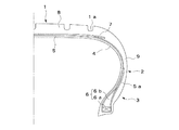
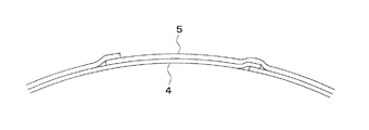
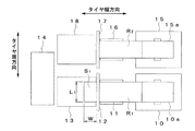
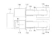
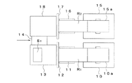
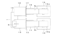
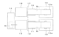
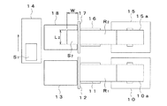
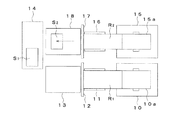
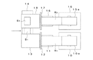
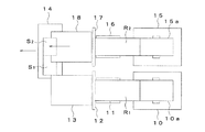
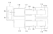
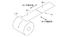
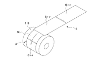
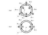
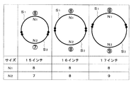
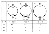
図1乃至図20は本発明の一実施形態を示すもので、図1は空気入りタイヤの部分正面断面図、図2はカーカス及びインナーライナのスプライス部を示す側面図、図3乃至図12はシート状ゴムの成形工程を示す平面図、図13及び図14は成形ドラムへのシート状ゴムの巻き付け工程を示す斜視図、図15及び図16はカーカス及びインナーライナの概略側面図、図17及び図18は分割比の組み合わせ例を示す図、図19及び図20は試験結果を示す図である。 1 to 20 show an embodiment of the present invention. FIG. 1 is a partial front sectional view of a pneumatic tire, FIG. 2 is a side view showing a splice portion of a carcass and an inner liner, and FIGS. FIG. 13 and FIG. 14 are perspective views showing the process of winding the sheet rubber around the molding drum, FIGS. 15 and 16 are schematic side views of the carcass and inner liner, FIG. 17 and FIG. FIG. 18 is a diagram illustrating an example of combination of division ratios, and FIGS. 19 and 20 are diagrams illustrating test results.
同図に示す空気入りタイヤは、タイヤ外周面側に形成されるトレッド部1と、タイヤ幅方向両側に形成される一対のサイドウォール部2と、タイヤ幅方向両側に形成される一対のビード部3とから構成されている。また、この空気入りタイヤは、タイヤ内面側に配置されるインナーライナ4と、インナーライナ4の外側に配置されるカーカス5と、タイヤ幅方向両側に配置される一対のビード部材6と、カーカス5の外側に配置されるベルト7と、タイヤ外周面側に配置されるトレッド部材8と、タイヤ両側面側に配置される一対のサイドウォール部材9とから形成されている。
The pneumatic tire shown in the figure includes a
インナーライナ4は、ブチルゴムを主体とする気体透過性の低いシート状のゴムからなり、カーカス5の内周面側に配置される。
The
カーカス5は、複数本のカーカスコード5aがタイヤの周方向に配列されたシート状のゴムからなり、その幅方向両端側をビード部材を巻き込むようにタイヤ幅方向内側から外側に向けてサイドウォール部2側に折り返される。
The
ビード部材6は、金属線等のワイヤを束ねてなるビードコア6aと、断面略三角形状のゴムからなるビードフィラー6bとからなり、ビードフィラー6bはビードコア6aの外周側に配置される。
The
ベルト7はスチールや高強度繊維等からなるベルトコードをシート状のゴムで被覆してなり、カーカス5の外周面側に配置される。
The
トレッド部材8は押出成形によって形成されたゴムからなり、カーカス5の幅方向中央側及びベルト7の外周面側を覆うように配置され、その外周面にはトレッドパターンの溝1aが加硫成型時に形成される。
The
サイドウォール部材9は押出成形によって形成されたゴムからなり、カーカス5のタイヤ幅方向両側を覆うように配置される。
The
次に、本実施形態のタイヤ製造方法について説明する。尚、以下に説明する工程はタイヤ製造工程の一部を示すもので、他の製造工程については従来と同等であるため省略する。 Next, the tire manufacturing method of this embodiment will be described. In addition, the process demonstrated below shows a part of tire manufacturing process, and since it is equivalent to the former about other manufacturing processes, it abbreviate | omits.
まず、インナーライナ4及びカーカス5となるシート状ゴムの成形工程では、図3に示すように第1の台車10のドラム10aから引き出された第1の帯状ゴムR1 を第1のコンベア11によって長手方向(タイヤ幅方向一方)に搬送するとともに、カッター12によって幅方向(タイヤ周方向)に所定の幅Wで切断することにより、1枚目の分割シートS1 を形成する。次に、図4に示すように一枚目の分割シートS1 を第2のコンベア13に移載し、図5に示すようにトレイ14をタイヤ幅方向他方に移動して第2のコンベア13の下方に配置する。続いて、図6に示すように第2のコンベア13によって1枚目の分割シートS1 をタイヤ幅方向一方に送り出しながらトレイ14を同一方向に移動することにより、図7に示すように1枚目の分割シートS1 をトレイ14に移載する。この後、図8に示すように第2の台車15のドラム15aから引き出された第2の帯状ゴムR2 を第3のコンベア16によって長手方向(タイヤ幅方向一方)に搬送するとともに、カッター17によって幅方向(タイヤ周方向)に所定の幅Wで切断することにより、2枚目の分割シートS2 を形成する。次に、トレイ14をタイヤ周方向一方に移動した後、図9に示すように2枚目の分割シートS2 を第4のコンベア18に移載し、図10に示すようにトレイ14をタイヤ幅方向他方に移動して第4のコンベア18の下方に配置する。続いて、図11に示すように第4のコンベア18によって2枚目の分割シートS2 をタイヤ幅方向一方に送り出しながらトレイ14を同一方向に移動することにより、図12に示すように2枚目の分割シートS2 をタイヤ周方向一端側が1枚目の分割シートS1 のタイヤ周方向他端側に重なり合うようにトレイ14に移載し、各分割シートS1 ,S2 をスプライスすることにより、インナーライナ4またはカーカス5となるシート状ゴムを形成する。
First, in the step of forming the sheet rubber to be the
次に、前述のようにしてシート状のインナーライナ4(分割シートS1-1 ,S2-1 )及びカーカス5(分割シートS1-2 ,S2-2 )を形成した後は、図13に示すようにインナーライナ4を成形ドラム19に巻き付けてタイヤ周方向両端部をスプライスし、図14に示すようにカーカス5をインナーライナ4の上から成形ドラム19に巻き付けてタイヤ周方向両端部をスプライスすることにより、図2に示すようにインナーライナ4とカーカス5を積層する。
Next, after the sheet-like inner liner 4 (divided sheets S1-1 and S2-1) and the carcass 5 (divided sheets S1-2 and S2-2) are formed as described above, as shown in FIG. The
この場合、インナーライナ4及びカーカス5を、合計値がタイヤの呼び径(インチサイズ)の値となる複数の整数値N1 ,N2 ,…でタイヤ周方向に分割するとともに、互いにスプライス位置がタイヤ周方向にずれるように配置する。
In this case, the
即ち、図15に示すようにインナーライナ4及びカーカス5を互いにタイヤ周方向の分割比が異なるように形成する。例えば、タイヤの呼び径が15インチの場合、図15(a) に示すように、インナーライナ4の1枚目、2枚目及び3枚目の分割シートS1-1 ,S2-1 ,S3-1 の整数値N1 ,N2 ,N3 をそれぞれ「5」とし、カーカス5の1枚目の分割シートS1-2 の整数値N1 を「8」、2枚目の分割シートS2-2 の整数値N2 を「7」として、インナーライナ4の分割シートS1-1 ,S2-1 ,S3-1 とカーカス5の分割シートS1-2 ,S2-2 のスプライス位置がタイヤ周方向にずれるように配置する。また、図15(b) に示すように、インナーライナ4の1枚目の分割シートS1-1 の整数値N1 を「5」、2枚目の分割シートS2-1 の整数値N2 を「10」とし、カーカス5の1枚目の分割シートS1-2 の整数値N1 を「9」、2枚目の分割シートS2-2 の整数値N2 を「6」として、インナーライナ4の分割シートS1-1 ,S2-1 とカーカス5の分割シートS1-2 ,S2-2 のスプライス位置がタイヤ周方向にずれるように配置する。
That is, as shown in FIG. 15, the
更に、図16に示すようにインナーライナ4及びカーカス5を互いにタイヤ周方向の分割比が等しくなるように形成し、互いにスプライス位置がタイヤ径方向の中心に対して点対称となるように配置するようにしてもよい。例えば、タイヤの呼び径が15インチの場合、図16(a) に示すように、インナーライナ4の1枚目、2枚目及び3枚目の分割シートS1-1 ,S2-1 ,S3-1 の整数値N1 ,N2 ,N3 をそれぞれ「5」とし、カーカス5の1枚目、2枚目及び3枚目の分割シートS1-2 ,S2-2 ,S3-2 の整数値N1 ,N2 ,N3 もそれぞれ「5」として、インナーライナ4の分割シートS1-1 ,S2-1 ,S3-1 とカーカス5の分割シートS1-2 ,S2-2 ,S3-2 のスプライス位置がタイヤ周方向にずれるように点対称に配置する。また、タイヤの呼び径が16インチの場合、図16(b) に示すように、インナーライナ4の1枚目の分割シートS1-1 の整数値N1 を「15」、2枚目の分割シートS2-1 の整数値N2 を「1」とし、カーカス5の1枚目の分割シートS1-2 の整数値N1 を「1」、2枚目の分割シートS2-2 の整数値N2 を「15」として、インナーライナ4の分割シートS1-1 ,S2-1 とカーカス5の分割シートS1-2 ,S2-2 のスプライス位置がタイヤ周方向に点対称にずれるように配置する。
Further, as shown in FIG. 16, the
また、互いにタイヤの呼び径が異なる複数種類のタイヤを製造する場合には、少なくとも一部の分割シートが互いに共通の整数値N1 ,N2 ,…に対応したタイヤ周方向長さを有するシート状ゴムを用いる。 When manufacturing a plurality of types of tires having different tire nominal diameters, at least some of the divided sheets have a tire circumferential length corresponding to a common integer value N1, N2,... Is used.
例えば、呼び径が15インチ、16インチ及び17インチのタイヤを製造する場合、図17に示すように、15インチでは1枚目の分割シートS1 の整数値N1 を「8」、2枚目の分割シートS2 の整数値N2 を「7」とし、16インチでは1枚目の分割シートS1 の整数値N1 及び2枚目の分割シートS2 の整数値N2 をそれぞれ「8」とし、17インチでは1枚目の分割シートS1 の整数値N1 を「8」、2枚目の分割シートS2 の整数値N2 を「9」とすることにより、1枚目の分割シートS1 (整数値N1 =「8」)を各インチサイズで共用することができる。 For example, when manufacturing tires having nominal diameters of 15 inches, 16 inches, and 17 inches, as shown in FIG. 17, the integer value N1 of the first divided sheet S1 is set to “8” and the second sheet is 15 inches. The integer value N2 of the divided sheet S2 is set to “7”, the integer value N1 of the first divided sheet S1 and the integer value N2 of the second divided sheet S2 are set to “8” for 16 inches, and 1 for 17 inches. By setting the integer value N1 of the first divided sheet S1 to “8” and the integer value N2 of the second divided sheet S2 to “9”, the first divided sheet S1 (integer value N1 = “8”). ) Can be shared by each inch size.
また、呼び径が16インチ、17インチ及び18インチのタイヤを製造する場合、図18に示すように、16インチでは1枚目の分割シートS1 の整数値N1 を「15」、2枚目の分割シートS2 の整数値N2 を「1」とし、17インチでは1枚目の分割シートS1 の整数値N1 を「15」、2枚目の分割シートS2 の整数値N2 及び3枚目の分割シートS3 の整数値N3 をそれぞれ「1」とし、18インチでは1枚目の分割シートS1 の整数値N1 を「15」、2枚目の分割シートS2 の整数値N2 を「3」とすることにより、1枚目の分割シートS1 (整数値N1 =「15」)を各インチサイズで共用することができる。 Further, when manufacturing tires having nominal diameters of 16 inches, 17 inches, and 18 inches, as shown in FIG. 18, the integer value N1 of the first divided sheet S1 is set to “15” and the second sheet is 16 inches. The integer value N2 of the divided sheet S2 is set to “1”, and for 17 inches, the integer value N1 of the first divided sheet S1 is “15”, the integer value N2 of the second divided sheet S2 and the third divided sheet. By setting the integer value N3 of S3 to "1", and for 18 inches, the integer value N1 of the first divided sheet S1 is "15", and the integer value N2 of the second divided sheet S2 is "3". The first divided sheet S1 (integer value N1 = “15”) can be shared by each inch size.
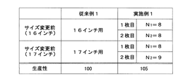
ここで、本発明の実施例1及び従来例1について、タイヤの生産性の試験を行ったところ、図19に示す結果が得られた。従来例1ではタイヤ周方向に分割していない16インチ用のシート状ゴムを用いて16インチの未加硫タイヤを成形した後、17インチ用の他のシート状ゴムを用いて17インチの未加硫タイヤを成形した。一方、実施例1では、タイヤ周方向に二分割したシート状ゴムを用い、1枚目及び2枚目の分割シートS1 ,S2 の整数値N1 ,N2 をそれぞれ「8」として16インチの未加硫タイヤを成形した後、1枚目の分割シートS1 の整数値N1 を「8」、2枚目の分割シートS2 の整数値N2 を「9」として17インチの未加硫タイヤを成形した。 Here, when the tire productivity test was performed on Example 1 and Conventional Example 1 of the present invention, the results shown in FIG. 19 were obtained. In Conventional Example 1, a 16-inch unvulcanized tire is molded using a 16-inch sheet rubber not divided in the tire circumferential direction, and then a 17-inch non-vulcanized tire is formed using another 17-inch rubber sheet. A vulcanized tire was molded. On the other hand, in Example 1, a sheet-like rubber divided into two in the tire circumferential direction is used, and the integer values N1 and N2 of the first and second divided sheets S1 and S2 are set to “8” and 16 inches are not added. After molding the vulcanized tire, a 17-inch unvulcanized tire was molded with the integer value N1 of the first divided sheet S1 being "8" and the integer value N2 of the second divided sheet S2 being "9".
この試験では、タイヤサイズ215/50R16のタイヤを100本成形した後、タイヤサイズ215/50R17のタイヤを100本成形した場合の所要時間から1日当たりの生産量を算出し、従来例1を100として指数化した値が大きいほど優位性があるとして評価した。試験の結果、従来例1ではサイズ変更時の段替作業に15分〜30分の時間を要したが、実施例1は、1枚目の分割シートS1 (整数値N1 =「8」)を各インチサイズで共用しているため、段替えの必要がなく、従来例1に比べて生産性に優れているという結果が得られた。 In this test, after 100 tires having a tire size of 215 / 50R16 were formed, the production amount per day was calculated from the time required when 100 tires having a tire size of 215 / 50R17 were formed. The larger the indexed value, the better. As a result of the test, in the conventional example 1, it took 15 to 30 minutes to change the size when changing the size, but in the first example, the first divided sheet S1 (integer value N1 = “8”) was used. Since each inch size is shared, there is no need to change the setting, and the result is that productivity is superior to Conventional Example 1.
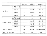
次に、本発明の実施例2,3及び従来例2について、タイヤ静バランスの試験を行ったところ、図20に示す結果が得られた。従来例2には、カーカスとインナーライナをそれぞれタイヤ周方向一箇所ずつスプライスし、互いにスプライス部がタイヤ周方向に一致するように重ね合わせたものを用いた。実施例2には、互いにタイヤ周方向の分割比が異なるカーカス及びインナーライナをスプライス位置がタイヤ周方向にずれるように配置したものを用いた。即ち、実施例2のカーカスには、1枚目の分割シートS1 の整数値N1 を「8」、2枚目の分割シートS2 の整数値N2 を「7」としたシート状ゴムを用い、インナーライナには、1枚目、2枚目及び3枚目の分割シートS1 ,S2 ,S3 に整数値N1 ,N2 ,N3 をそれぞれ「5」としたシート状ゴムを用いた。また、実施例3には、互いにタイヤ周方向の分割比が等しいカーカス及びインナーライナをスプライス位置がタイヤ径方向の中心に対して点対称となるように配置したものを用いた。即ち、実施例3のカーカス及びインナーライナには、1枚目、2枚目及び3枚目の分割シートS1 ,S2 ,S3 に整数値N1 ,N2 ,N3 をそれぞれ「5」としたシート状ゴムを用いた。尚、本試験は、タイヤサイズ205/60R15のタイヤを用いて行った。 Next, when Examples 2 and 3 of the present invention and Conventional Example 2 were tested for tire static balance, the results shown in FIG. 20 were obtained. In Conventional Example 2, a carcass and an inner liner were spliced one by one in the tire circumferential direction, and were superposed so that the splice portions coincided with each other in the tire circumferential direction. In Example 2, a carcass and an inner liner having different division ratios in the tire circumferential direction were arranged so that the splice position was shifted in the tire circumferential direction. That is, the carcass of the second embodiment uses a sheet-like rubber in which the integer value N1 of the first divided sheet S1 is "8" and the integer value N2 of the second divided sheet S2 is "7". The liner used was a sheet-like rubber having integer values N1, N2, and N3 of “5” for the first, second, and third divided sheets S1, S2, and S3. In Example 3, a carcass and an inner liner having the same division ratio in the tire circumferential direction are arranged so that the splice position is point-symmetric with respect to the center in the tire radial direction. That is, in the carcass and inner liner of Example 3, the first, second and third divided sheets S1, S2 and S3 are sheet-like rubbers in which integer values N1, N2 and N3 are set to “5”, respectively. Was used. This test was performed using tires having a tire size of 205 / 60R15.
この試験では、タイヤ静バランスをJASOC607により測定するとともに、従来例1を100として指数化し、指数の値が大きいほど優位性があるとして評価した。試験の結果、本発明の実施例2及び3は、それぞれ従来例2よりもタイヤ静バランス性に優れ、ユニフォミティが向上するという結果が得られた。 In this test, the tire static balance was measured by JASOC 607, and indexed with Conventional Example 1 as 100, and the higher the value of the index, the better. As a result of the test, Examples 2 and 3 of the present invention were superior to Conventional Example 2 in terms of tire static balance and resulted in improved uniformity.
このように、本実施形態によれば、カーカス5及びインナーライナ4となるシート状ゴムの分割シートS1 ,S2 ,…を、合計値がタイヤの呼び径の値となる複数の整数値N1 ,N2 ,…でタイヤ周方向に分割した位置でスプライスするようにしたので、一部の分割シートが互いに共通の整数値に対応したタイヤ周方向長さを有するシート状ゴムを用いることにより、一部の分割シートを共用することができ、タイヤ径方向のインチサイズが異なるタイヤへの段替時間の短縮を図ることができる。また、カーカス5及びインナーライナ4を互いにスプライス位置がタイヤ周方向にずれるように配置したので、タイヤ静バランス性を向上させることができ、ユニフォミティの改善を図ることができる。
As described above, according to the present embodiment, the sheet-like rubber divided sheets S1, S2,... That become the
この場合、互いにタイヤ周方向の分割比が異なるカーカス5及びインナーライナ4をタイヤ径方向に積層するようにしたので、スプライス位置をタイヤ周方向に容易にずらすことができ、ユニフォミティの改善に極めて有利である。
In this case, since the
また、互いにタイヤ周方向の分割比が等しいカーカス5及びインナーライナ4を、互いにスプライス位置がタイヤ径方向の中心に対して点対称となるように配置するようにしたので、スプライス位置をタイヤ周方向に等間隔でずらすことができ、ユニフォミティの改善効果をより一層高めることができる。
In addition, since the
更に、予め分割シート同士がスプライスされたカーカス5及びインナーライナ4をそれぞれ成形ドラム19に巻き付けてタイヤ周方向両端部をスプライスするようにしたので、成形ドラム19への巻き付け作業を容易に行うことができ、生産性の向上を図ることができる。
Furthermore, since the
尚、前記実施形態では、カーカス5及びインナーライナ4を成形する場合を示したが、本発明は他のタイヤ構成部材となるシート状ゴムにも適用することができる。
In the above embodiment, the
4…インナーライナ、5…カーカス、19…成形ドラム、S1 ,S2 ,S3 …分割シート。 4 ... inner liner, 5 ... carcass, 19 ... molding drum, S1, S2, S3 ... divided sheets.
Claims (10)
前記シート状ゴムの分割シートを、合計値がタイヤの呼び径の値となる複数の整数値でタイヤ周方向に分割した位置でスプライスし、
タイヤ径方向に積層される複数のシート状ゴムを互いに分割シートのスプライス位置がタイヤ周方向にずれるように配置した
ことを特徴とする空気入りタイヤ。 In the pneumatic tire formed by laminating the sheet-shaped rubber divided in the tire circumferential direction and spliced in the tire radial direction,
The sheet-like rubber split sheet is spliced at a position divided in the tire circumferential direction by a plurality of integer values whose total value is the value of the nominal diameter of the tire,
A pneumatic tire characterized in that a plurality of sheet-like rubbers laminated in the tire radial direction are arranged such that the splice positions of the divided sheets are shifted in the tire circumferential direction.
ことを特徴とする請求項1記載の空気入りタイヤ。 The pneumatic tire according to claim 1, wherein the plurality of sheet-like rubbers laminated in the tire radial direction are formed such that the division ratios of the divided sheets in the tire circumferential direction are different from each other.
ことを特徴とする請求項1記載の空気入りタイヤ。 A plurality of sheet-like rubbers stacked in the tire radial direction are formed so that the split ratios of the split sheets in the tire circumferential direction are equal to each other, and the splice positions are point-symmetric with respect to the center in the tire radial direction. The pneumatic tire according to claim 1, wherein
ことを特徴とする請求項1、2または3記載の空気入りタイヤ。 The pneumatic tire according to claim 1, 2 or 3, wherein the plurality of sheet-like rubbers are a carcass and an inner liner, respectively.
前記シート状ゴムの分割シートを、合計値がタイヤの呼び径の値となる複数の整数値でタイヤ周方向に分割した位置でスプライスし、
複数のシート状ゴムを互いに分割シートのスプライス位置がタイヤ周方向にずれるように配置して積層する
ことを特徴とする空気入りタイヤの製造方法。 In the manufacturing method of a pneumatic tire in which the sheet rubber is divided in the tire circumferential direction and spliced and laminated in the tire radial direction,
The sheet-like rubber split sheet is spliced at a position divided in the tire circumferential direction by a plurality of integer values whose total value is the value of the nominal diameter of the tire,
A method for producing a pneumatic tire, comprising: laminating a plurality of sheet-like rubbers so that the splice positions of the divided sheets are shifted in the tire circumferential direction.
ことを特徴とする請求項5記載の空気入りタイヤの製造方法。 The method for producing a pneumatic tire according to claim 5, wherein a plurality of sheet-like rubbers having different division ratios in the tire circumferential direction of the divided sheets are laminated in the tire radial direction.
ことを特徴とする請求項5記載の空気入りタイヤの製造方法。 A plurality of sheet-like rubbers having the same split ratio in the tire circumferential direction of the split sheets are arranged so that the splice positions are point-symmetric with respect to the center in the tire radial direction and laminated in the tire radial direction. The method for producing a pneumatic tire according to claim 5.
ことを特徴とする請求項5、6または7記載の空気入りタイヤの製造方法。 The method for producing a pneumatic tire according to claim 5, 6 or 7, wherein a sheet-like rubber, in which the divided sheets are spliced in advance, is wound around a molding drum and both ends in the circumferential direction of the tire are spliced.
ことを特徴とする請求項5、6、7または8記載の空気入りタイヤの製造方法。 A sheet-like rubber having a tire circumferential direction length corresponding to an integer value common to at least some of the divided sheets is used as the sheet-like rubber of a plurality of types of tires having different tire nominal diameters. Item 9. The method for producing a pneumatic tire according to Item 5, 6, 7 or 8.
ことを特徴とする請求項5、6、7、8または9記載の空気入りタイヤの製造方法。 The method for producing a pneumatic tire according to claim 5, 6, 7, 8, or 9, wherein the plurality of sheet-like rubbers are a carcass and an inner liner, respectively.
Priority Applications (6)
| Application Number | Priority Date | Filing Date | Title |
|---|---|---|---|
| JP2008322470A JP2010143386A (en) | 2008-12-18 | 2008-12-18 | Pneumatic tire and method of manufacturing the same |
| US12/613,337 US20100154954A1 (en) | 2008-12-18 | 2009-11-05 | Pneumatic tire and method for manufacturing the same |
| RU2009143688/05A RU2423239C1 (en) | 2008-12-18 | 2009-11-25 | Pneumatic tire and method of its production |
| DE102009055692A DE102009055692A1 (en) | 2008-12-18 | 2009-11-25 | Pneumatic tire and method of making the same |
| CN2009102532702A CN101913307A (en) | 2008-12-18 | 2009-12-11 | Pneumatic tire and method for manufacturing the same |
| US13/750,435 US20130133813A1 (en) | 2008-12-18 | 2013-01-25 | Pneumatic tire and method for manufacturing the same |
Applications Claiming Priority (1)
| Application Number | Priority Date | Filing Date | Title |
|---|---|---|---|
| JP2008322470A JP2010143386A (en) | 2008-12-18 | 2008-12-18 | Pneumatic tire and method of manufacturing the same |
Publications (1)
| Publication Number | Publication Date |
|---|---|
| JP2010143386A true JP2010143386A (en) | 2010-07-01 |
Family
ID=42221089
Family Applications (1)
| Application Number | Title | Priority Date | Filing Date |
|---|---|---|---|
| JP2008322470A Pending JP2010143386A (en) | 2008-12-18 | 2008-12-18 | Pneumatic tire and method of manufacturing the same |
Country Status (5)
| Country | Link |
|---|---|
| US (2) | US20100154954A1 (en) |
| JP (1) | JP2010143386A (en) |
| CN (1) | CN101913307A (en) |
| DE (1) | DE102009055692A1 (en) |
| RU (1) | RU2423239C1 (en) |
Cited By (2)
| Publication number | Priority date | Publication date | Assignee | Title |
|---|---|---|---|---|
| JP2012240658A (en) * | 2011-05-24 | 2012-12-10 | Yokohama Rubber Co Ltd:The | Pneumatic tire |
| WO2014054597A1 (en) * | 2012-10-03 | 2014-04-10 | 横浜ゴム株式会社 | Pneumatic tire |
Families Citing this family (4)
| Publication number | Priority date | Publication date | Assignee | Title |
|---|---|---|---|---|
| JPWO2014054584A1 (en) * | 2012-10-03 | 2016-08-25 | 横浜ゴム株式会社 | Pneumatic tire |
| WO2016103077A1 (en) * | 2014-12-24 | 2016-06-30 | Pirelli Tyre S.P.A. | Plant for collecting or dispensing an elongated element for building tyres and method for collecting or dispensing an elongated element wound in reels |
| JP7403305B2 (en) * | 2019-12-13 | 2023-12-22 | Toyo Tire株式会社 | Pneumatic tire and its manufacturing method |
| JP7602994B2 (en) * | 2021-12-14 | 2024-12-19 | 株式会社ブリヂストン | Method and apparatus for manufacturing raw tire |
Citations (3)
| Publication number | Priority date | Publication date | Assignee | Title |
|---|---|---|---|---|
| JPH10217711A (en) * | 1997-02-04 | 1998-08-18 | Yokohama Rubber Co Ltd:The | Pneumatic tire and manufacture thereof |
| JP2004175157A (en) * | 2002-11-25 | 2004-06-24 | Bridgestone Corp | Pneumatic tire |
| JP2005246622A (en) * | 2004-03-01 | 2005-09-15 | Bridgestone Corp | Green tire molding method and pneumatic tire |
Family Cites Families (16)
| Publication number | Priority date | Publication date | Assignee | Title |
|---|---|---|---|---|
| US1295014A (en) * | 1916-09-28 | 1919-02-18 | Rene Hustinx | Outer cover for pneumatic tires for bicycles, motor-vehicles, and the like. |
| US1918553A (en) * | 1929-10-04 | 1933-07-18 | Goodyear Tire & Rubber | Pneumatic tire and method of making it |
| BE508165A (en) * | 1951-03-21 | |||
| US3826297A (en) * | 1972-10-26 | 1974-07-30 | Steelastic Co | Radial tire carcass |
| IT978572B (en) * | 1973-01-29 | 1974-09-20 | Pirelli | METHOD FOR THE MANUFACTURE OF SEMI-FINISHED PRODUCTS IN RUBBERIZED FABRIC IN PARTICULAR OF CIN TURAN INTERMEDIATES FOR TIRES |
| SU1725516A1 (en) * | 1990-04-27 | 1994-07-30 | Всесоюзный Научно-Исследовательский И Конструкторский Институт По Оборудованию Для Шинной Промышленности | Method of applying resilient tape material to rotating object |
| JPH0764163B2 (en) * | 1990-07-06 | 1995-07-12 | 住友ゴム工業株式会社 | Pneumatic tire |
| JPH06115313A (en) * | 1992-10-01 | 1994-04-26 | Yokohama Rubber Co Ltd:The | Pneumatic radial tire |
| JP3390273B2 (en) | 1994-11-30 | 2003-03-24 | 横浜ゴム株式会社 | Method and apparatus for feeding strip material |
| RU2184036C1 (en) * | 2000-11-02 | 2002-06-27 | Открытое акционерное общество "Научно-исследовательский и конструкторский институт по оборудованию для шинной промышленности" | Device for feeding of belt material to assembly drum |
| JP4346436B2 (en) * | 2003-12-25 | 2009-10-21 | 横浜ゴム株式会社 | Pneumatic tire and manufacturing method thereof |
| JP4816860B2 (en) | 2004-11-26 | 2011-11-16 | 横浜ゴム株式会社 | Method and apparatus for forming sheet-like member |
| US20060137804A1 (en) * | 2004-12-23 | 2006-06-29 | Downing Daniel R | Method for making tire ply |
| JP4275148B2 (en) * | 2006-04-28 | 2009-06-10 | 横浜ゴム株式会社 | Pneumatic tire and manufacturing method thereof |
| JP4725416B2 (en) * | 2006-05-26 | 2011-07-13 | 横浜ゴム株式会社 | Pneumatic tire manufacturing method |
| JP2008221638A (en) * | 2007-03-13 | 2008-09-25 | Bridgestone Corp | Manufacturing method and manufacturing apparatus for sheet-form tire constituting member |
-
2008
- 2008-12-18 JP JP2008322470A patent/JP2010143386A/en active Pending
-
2009
- 2009-11-05 US US12/613,337 patent/US20100154954A1/en not_active Abandoned
- 2009-11-25 RU RU2009143688/05A patent/RU2423239C1/en not_active IP Right Cessation
- 2009-11-25 DE DE102009055692A patent/DE102009055692A1/en not_active Withdrawn
- 2009-12-11 CN CN2009102532702A patent/CN101913307A/en active Pending
-
2013
- 2013-01-25 US US13/750,435 patent/US20130133813A1/en not_active Abandoned
Patent Citations (3)
| Publication number | Priority date | Publication date | Assignee | Title |
|---|---|---|---|---|
| JPH10217711A (en) * | 1997-02-04 | 1998-08-18 | Yokohama Rubber Co Ltd:The | Pneumatic tire and manufacture thereof |
| JP2004175157A (en) * | 2002-11-25 | 2004-06-24 | Bridgestone Corp | Pneumatic tire |
| JP2005246622A (en) * | 2004-03-01 | 2005-09-15 | Bridgestone Corp | Green tire molding method and pneumatic tire |
Cited By (3)
| Publication number | Priority date | Publication date | Assignee | Title |
|---|---|---|---|---|
| JP2012240658A (en) * | 2011-05-24 | 2012-12-10 | Yokohama Rubber Co Ltd:The | Pneumatic tire |
| WO2014054597A1 (en) * | 2012-10-03 | 2014-04-10 | 横浜ゴム株式会社 | Pneumatic tire |
| US9895934B2 (en) | 2012-10-03 | 2018-02-20 | The Yokohama Rubber Co., Ltd. | Pneumatic tire |
Also Published As
| Publication number | Publication date |
|---|---|
| RU2423239C1 (en) | 2011-07-10 |
| US20100154954A1 (en) | 2010-06-24 |
| RU2009143688A (en) | 2011-05-27 |
| US20130133813A1 (en) | 2013-05-30 |
| CN101913307A (en) | 2010-12-15 |
| DE102009055692A1 (en) | 2010-07-01 |
Similar Documents
| Publication | Publication Date | Title |
|---|---|---|
| JP2010167829A (en) | Pneumatic tire and method for manufacturing the same | |
| JP2010143386A (en) | Pneumatic tire and method of manufacturing the same | |
| CN100480067C (en) | Pneumatic tire and method of manufacturing the same | |
| JP2010052472A (en) | Pneumatic tire and method for manufacturing the same | |
| US20180178585A1 (en) | Tire ply joint configuration | |
| US20240375442A1 (en) | Tire and tire production method | |
| US20110146887A1 (en) | Tire ply and method of manufacture | |
| JP2008254400A (en) | Manufacturing method for pneumatic tire for heavy load, and pneumatic tire for heavy load | |
| JP2014008928A (en) | Pneumatic tire, and manufacturing method for the same | |
| JP2008290607A (en) | Pneumatic radial tire | |
| EP2990191B1 (en) | Tire ply and method of its manufacture | |
| JP2016107932A (en) | Tire, method for manufacturing tire, and treat composite material molding apparatus | |
| JP2008290609A (en) | Pneumatic radial tire | |
| JP2008030660A (en) | Pneumatic tire and manufacturing method thereof | |
| JP2005041328A (en) | Pneumatic tire | |
| JP2011025807A (en) | Pneumatic tire and method of manufacturing the same | |
| JP2001038822A (en) | Large-sized pneumatic tire and production thereof | |
| JP2005088816A (en) | Pneumatic tire and its method of manufacture | |
| JPS5959502A (en) | Pneumatic tire | |
| WO2018016182A1 (en) | Method for manufacturing pneumatic tire and pneumatic tire | |
| JP2011156925A (en) | Pneumatic tire | |
| JP2007230394A (en) | Pneumatic radial tire | |
| US20120168060A1 (en) | Tire mandrel | |
| JP6147577B2 (en) | Pneumatic tire | |
| JP2003145643A (en) | Manufacturing method for tire, and tire |
Legal Events
| Date | Code | Title | Description |
|---|---|---|---|
| A621 | Written request for application examination |
Free format text: JAPANESE INTERMEDIATE CODE: A621 Effective date: 20111208 |
|
| A977 | Report on retrieval |
Free format text: JAPANESE INTERMEDIATE CODE: A971007 Effective date: 20130110 |
|
| A131 | Notification of reasons for refusal |
Free format text: JAPANESE INTERMEDIATE CODE: A131 Effective date: 20130212 |
|
| A02 | Decision of refusal |
Free format text: JAPANESE INTERMEDIATE CODE: A02 Effective date: 20130703 |