JP2010143592A - Packaging container - Google Patents
Packaging container Download PDFInfo
- Publication number
- JP2010143592A JP2010143592A JP2008320269A JP2008320269A JP2010143592A JP 2010143592 A JP2010143592 A JP 2010143592A JP 2008320269 A JP2008320269 A JP 2008320269A JP 2008320269 A JP2008320269 A JP 2008320269A JP 2010143592 A JP2010143592 A JP 2010143592A
- Authority
- JP
- Japan
- Prior art keywords
- opening
- cover member
- packaging container
- assisting line
- back cover
- Prior art date
- Legal status (The legal status is an assumption and is not a legal conclusion. Google has not performed a legal analysis and makes no representation as to the accuracy of the status listed.)
- Granted
Links
Images


Classifications
-
- B—PERFORMING OPERATIONS; TRANSPORTING
- B65—CONVEYING; PACKING; STORING; HANDLING THIN OR FILAMENTARY MATERIAL
- B65D—CONTAINERS FOR STORAGE OR TRANSPORT OF ARTICLES OR MATERIALS, e.g. BAGS, BARRELS, BOTTLES, BOXES, CANS, CARTONS, CRATES, DRUMS, JARS, TANKS, HOPPERS, FORWARDING CONTAINERS; ACCESSORIES, CLOSURES, OR FITTINGS THEREFOR; PACKAGING ELEMENTS; PACKAGES
- B65D75/00—Packages comprising articles or materials partially or wholly enclosed in strips, sheets, blanks, tubes or webs of flexible sheet material, e.g. in folded wrappers
- B65D75/28—Articles or materials wholly enclosed in composite wrappers, i.e. wrappers formed by associating or interconnecting two or more sheets or blanks
- B65D75/30—Articles or materials enclosed between two opposed sheets or blanks having their margins united, e.g. by pressure-sensitive adhesive, crimping, heat-sealing, or welding
- B65D75/32—Articles or materials enclosed between two opposed sheets or blanks having their margins united, e.g. by pressure-sensitive adhesive, crimping, heat-sealing, or welding one or both sheets or blanks being recessed to accommodate contents
- B65D75/36—Articles or materials enclosed between two opposed sheets or blanks having their margins united, e.g. by pressure-sensitive adhesive, crimping, heat-sealing, or welding one or both sheets or blanks being recessed to accommodate contents one sheet or blank being recessed and the other formed of relatively stiff flat sheet material, e.g. blister packages, the recess or recesses being preformed
- B65D75/366—Articles or materials enclosed between two opposed sheets or blanks having their margins united, e.g. by pressure-sensitive adhesive, crimping, heat-sealing, or welding one or both sheets or blanks being recessed to accommodate contents one sheet or blank being recessed and the other formed of relatively stiff flat sheet material, e.g. blister packages, the recess or recesses being preformed and forming one compartment
Landscapes
- Chemical & Material Sciences (AREA)
- Composite Materials (AREA)
- Engineering & Computer Science (AREA)
- Mechanical Engineering (AREA)
- Packages (AREA)
- Closures For Containers (AREA)
Abstract
Description
本発明は、物品を収容する包装容器に関し、特に、その開封作業を簡素化する技術に関する。 The present invention relates to a packaging container that accommodates articles, and more particularly to a technique that simplifies the opening operation.
従来、シート状のプラスチックによって成型されたカバー部材を有する包装容器が利用されている。例えば、特許文献1の包装容器では、物品を収容する収容室を構成する一対のカバー部材(特許文献1においてクラムシェル)の双方がシート状プラスチックによって成型されている。そして、当該カバー部材の外周部が溶着されて、包装容器が密封されている。
しかしながら、上記従来の包装容器は、その開封時に繁雑な作業を必要としていた。例えば、カバー部材の溶着されている部分をハサミ等で包装容器から切り離し、2つのカバーを分離するなどの作業が必要であった。 However, the conventional packaging container described above requires a complicated operation when opened. For example, it is necessary to separate the two covers by separating the welded portion of the cover member from the packaging container with scissors or the like.
本発明は、上記課題に鑑みてなされたものであって、その目的は、開封作業を簡素化できる包装容器を提供することにある。 This invention is made | formed in view of the said subject, The objective is to provide the packaging container which can simplify an opening operation | work.
上記課題を解決するために、本発明に係る包装容器は、互いに張り合わされて、それらの内側に物品を収容可能な収容室を構成する一対のカバー部材を備える包装容器であって、前記一対のカバー部材のうち少なくとも一方は、シート状のプラスチックによって一体的に成型されている。また、前記一方のカバー部材は、前記収容室に面する当該一方のカバー部材の一部に、線状に形成された開封補助線部によって囲まれ、前記包装容器の開封時に前記開封補助線部が破断されることによって開く開封部を有している。そして、前記一方のカバー部材は、その表面が前記開封補助線部において凹むように形成されている。 In order to solve the above-described problems, a packaging container according to the present invention is a packaging container that includes a pair of cover members that are attached to each other and that form a storage chamber that can store articles inside thereof. At least one of the cover members is integrally formed of sheet-like plastic. In addition, the one cover member is surrounded by a part of the one cover member facing the storage chamber by a line-shaped opening auxiliary line part, and the opening auxiliary line part is opened when the packaging container is opened. Has an opening portion that is opened by breaking. And the said one cover member is formed so that the surface may be dented in the said opening assistance line part.
本発明によれば、一方のカバー部材は、その表面が開封補助線部において凹むように形成されているので、開封補助線部が破断し易く、開封作業を簡素化できる。なお、前記一方のカバー部材の前記表面は、他方のカバー部材と向き合う当該一方のカバー部材の内面でもよいし、当該内面とは反対側の面である外面でもよい。 According to the present invention, since one cover member is formed such that the surface thereof is recessed in the opening assisting line portion, the opening assisting line portion is easily broken, and the opening operation can be simplified. The surface of the one cover member may be an inner surface of the one cover member facing the other cover member, or may be an outer surface that is a surface opposite to the inner surface.
また、本発明の一態様では、前記開封補助線部には、前記一方のカバー部材の前記表面を凹ませる凹部が形成されてもよい。この態様によれば、凹部の深さを調整することによって、開封に要する力を調整できる。 Moreover, in one aspect of the present invention, the opening assisting line portion may be formed with a recess for recessing the surface of the one cover member. According to this aspect, the force required for opening can be adjusted by adjusting the depth of the recess.
また、この態様では、前記開封補助線部に、当該開封補助線部の延伸方向に並ぶ複数の前記凹部が形成されてもよい。また、前記凹部は前記開封補助線部の延伸方向に伸びる溝を呈してもよい。また、前記開封補助線部には、前記一方のカバー部材を貫通し、当該一方のカバー部材の前記表面を凹ませる複数の穴が形成され、前記複数の凹部と前記複数の穴は、前記開封補助線部において混在するように当該開封補助線部の延伸方向に並んでもよい。この場合、さらに開封補助線部が破断し易く、開封作業をさらに簡素化できる。また、隣接する2つの前記凹部の間隔は、前記カバー部材の厚さより小さくてもよい。これによって、複数の凹部が細かく設けられることとなり、開封部を滑らかに開くことができる。 Moreover, in this aspect, a plurality of the concave portions arranged in the extending direction of the opening assisting line portion may be formed in the opening assisting line portion. Moreover, the said recessed part may exhibit the groove | channel extended in the extending | stretching direction of the said opening assistance wire | line part. Further, the opening assisting line portion is formed with a plurality of holes penetrating the one cover member and denting the surface of the one cover member, and the plurality of recesses and the plurality of holes are formed in the opening opening. You may line up in the extending | stretching direction of the said opening auxiliary | assistant line part so that it may mix in an auxiliary line part. In this case, the opening assisting line portion is more easily broken, and the opening operation can be further simplified. Moreover, the space | interval of two said adjacent recessed parts may be smaller than the thickness of the said cover member. Thereby, a plurality of concave portions are provided finely, and the opening portion can be opened smoothly.
また、本発明の他の態様では、前記一方のカバー部材には開口が形成され、前記開封補助線部は前記開口の縁から延伸して前記開封部を囲んでもよい。この態様によれば、開封作業を行う作業者が、開口に指等を入れて開封部を摘み、当該開封部を引っ張り、開封補助線部を破断させることができる。 In another aspect of the present invention, an opening may be formed in the one cover member, and the opening assisting line portion may extend from an edge of the opening to surround the opening portion. According to this aspect, an operator who performs an opening operation can put a finger or the like into the opening, pick the opening portion, pull the opening portion, and break the opening assisting line portion.
また、この態様では、前記開封補助線部の端部には切り込みが形成され、当該切り込みが前記開口に連なってもよい。これによって、開封補助線部が破断し易くなり、さらに開封作業を簡素化できる。 In this aspect, a cut may be formed at the end of the opening assisting line portion, and the cut may be continuous with the opening. As a result, the opening assisting line portion is easily broken, and the opening operation can be simplified.
また、本発明の他の態様では、前記包装容器は、当該包装容器の内側に、湾曲可能に形成されるとともに前記開封部に沿って配置されるパネルを有してもよい。そして、前記パネルは、その外周縁が前記開封補助線部に沿って延伸するよう配置されるとともに、前記開封部より大きくてもよい。この態様によれば、開封部を開くことによってカバー部材に形成される開口の縁に、パネルの外周縁が引っ掛かるので、開封部を開いた直後に、包装容器から物品が落下することを抑制できる。 Moreover, in the other aspect of this invention, the said packaging container may have a panel arrange | positioned along the said opening part while it is formed inside the said packaging container so that it can curve. And the said panel may be larger than the said opening part while being arrange | positioned so that the outer periphery may extend along the said opening assistance line part. According to this aspect, since the outer peripheral edge of the panel is caught on the edge of the opening formed in the cover member by opening the opening portion, it is possible to suppress the article from falling from the packaging container immediately after opening the opening portion. .
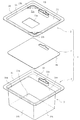
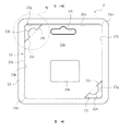
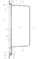
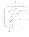
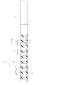
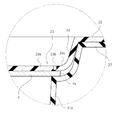
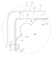
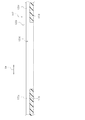
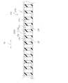
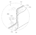
以下、本発明の一実施形態について図面を参照しながら説明する。図1は本発明の実施形態の例である包装容器1の分解斜視図である。図2は包装容器1が有する裏カバー部材2を包装容器1の外から臨む図であり、図3は図2に示すIII−III線での断面図である。なお、図3には、裏カバー部材2に加えて、包装容器1が有する表カバー部材3が示されている。図4は図2に示す破線IVで囲まれた部分の拡大図であり、図5は図4に示すV−V線での断面図である。図6は図3に示す破線VIで囲まれた部分の拡大図である。
Hereinafter, an embodiment of the present invention will be described with reference to the drawings. FIG. 1 is an exploded perspective view of a
図1に示すように、包装容器1は、裏カバー部材2と表カバー部材3とを有している。裏カバー部材2と、表カバー部材3は、互いに張り合わされ、それらの内側に、物品を収容可能な収容室10を構成している(図3参照)。収容室10には、例えば、電子機器や、電子機器の付属品が収容される。包装容器1は所謂ブリスターパックであり、この例では、裏カバー部材2と表カバー部材3のそれぞれが、シート状のプラスチック(例えば、ポリスチレン樹脂や、塩化ビニル系樹脂、ポリプロピレン樹脂、ポリエチレン樹脂、アクリル系樹脂、ポリエチレンテレフタート樹脂などの熱可塑性樹脂)によって一体的に成型されている。裏カバー部材2と表カバー部材3は、収容室10に収容される物品が外から見えるように、例えば透明のプラスチックによって成型される。なお、裏カバー部材2と表カバー部材3は、異なる材料によって成型されてもよい。
As shown in FIG. 1, the
表カバー部材3は、その外周縁に、裏カバー部材2と向き合う四角い枠状のフランジ部32を有している。また、表カバー部材3におけるフランジ部32の内側の部分は凹んでおり、フランジ部32の内側には、収容室10に収容される物品を収容可能な大きさの凹部である収容凹部31が設けられている。この例では、収容凹部31は、収容凹部31の底に位置する部分に略矩形の前壁部31aを有している。収容凹部31は、この前壁部31aと、前壁部31aの4つの縁において、それぞれ立つ4つの側壁部31bとによって構成されている。包装容器1は、その使用時(例えば物品を収容した複数の包装容器1を陳列する時)には、前壁部31aを前面にして配置される。なお、フランジ部32の内側には、1つの側壁部31bの上縁から広がり、裏カバー部材2と向き合う対向部33が設けられている。この対向部33には穴33aが形成されており、包装容器1の使用時には、当該穴33aに包装容器1を吊り下げるためのフック等が通される。
The
図3に示すように、裏カバー部材2は、表カバー部材3の収容凹部31を閉じるように表カバー部材3に張り合わされ、表カバー部材3とともに、収容凹部31の内側に収容室10を構成する。具体的には、裏カバー部材2は略板状に形成され、その外周縁には、表カバー部材3のフランジ部32に向き合う四角い枠状のフランジ部22が設けられている(図2参照)。そして、フランジ部22が、例えば、熱溶着や接着剤によって、フランジ部32に張り合わされる。また、フランジ部22は、ステープラ等の留め具によってフランジ部32に張り合わされてもよい。
As shown in FIG. 3, the
裏カバー部材2におけるフランジ部22の内側の部分は、表カバー部材3側に僅かに凹んでおり、フランジ部22の内側には、フランジ部22の内周縁から垂下する内壁部24と、内壁部24によって囲まれる板状の後壁部23が設けられている(図1参照)。フランジ部22がフランジ部32に張り合わされると、内壁部24はフランジ部32の内側に嵌り、後壁部23が収容凹部31を閉じる(図3参照)。なお、この後壁部23における穴33aに対応する部分には、穴23Lが形成されている。包装容器1の使用時には、穴33aと穴23Lの双方に、包装容器1を吊り下げるためのフック等が通される。
The inner portion of the
図2又は図4に示すように、後壁部23には、線状の開封補助線部23bが設けられている。後壁部23は、その表面が開封補助線部23bにおいて凹むように形成され、開封補助線部23bにおける裏カバー部材2の強度は、当該裏カバー部材2の他の部分の強度より低くなっている。また、後壁部23には、開封補助線部23bによって囲まれる板状の開封部23aが設けられている。すなわち、開封部23aの外周縁に開封補助線部23bが設けられている。包装容器1の開封時には、開封補助線部23bが破断することによって、開封部23aが開く。例えば、作業者が、開封部23aの一部(例えば、後述する摘み部23h)を包装容器1の外側に引っ張り、後壁部23を開封補助線部23bにおいて引き裂くと、開封部23aが開く。開封部23aは、収容室10に面しており(図3参照)、開封部23aが開いたことによって後壁部23に形成される開口から、収容室10に配置されている物品を取り出すことが可能となる。
As shown in FIG. 2 or FIG. 4, the
図5に示すように、開封補助線部23bには、後壁部23の表面を凹ませる凹部23cが形成されている。凹部23cは後壁部23を貫通しておらず、凹部23cには、当該凹部23cの底を構成する底部23fが設けられている。この例では、開封補助線部23bには、当該開封補助線部23bの延伸方向(図4又は図5においてDeの示す方向)に並ぶ複数の凹部23cが形成され、各凹部23cに底部23fが設けられている。複数の凹部23cは、開封部23aを囲むように点線状(ミシン目状)に形成されている。隣接する2つの凹部23cを仕切る仕切り部23dは、開封補助線部23bの内側、すなわち開封部23aと、外側(後壁部23の外周縁23e側(図6参照))とを断続的に接続している。
As shown in FIG. 5, the opening assisting
また、この例では、裏カバー部材2の外面(収容室10とは反対側の面)に凹部23cが形成されており、各凹部23cは包装容器1の外側(収容室10とは反対側)に向かって開口している。底部23fは、裏カバー部材2の内面側(収容室10側)に設けられており、開封部23aが開かれる方向とは反対側に位置している。そのため、裏カバー部材2の内面側では、開封補助線部23bを介して、開封補助線部23bの内側(すなわち開封部23a)と、外側(外周縁23e側)とが連続的に繋がっている。包装容器1の開封時には、仕切り部23dと、底部23fとが順次切断され、それによって、開封部23aが開く。
Moreover, in this example, the recessed
また、開封補助線部23bの延伸方向にける凹部23cの幅Whと、仕切り部23dの幅Wpの双方が、裏カバー部材2の厚さTより小さくなっている。特に、この例では、隣接する2つの凹部23cの間隔Iも、裏カバー部材2の厚さTより小さくなっている。また、この例では、凹部23cの幅Whが、仕切り部23dの幅Wpより大きくなっている。さらに、凹部23cの深さDは、厚さTの半分の深さを超えている。
Further, both the width Wh of the
例えば、シート状のプラスチックから成型される裏カバー部材2の厚さTは、概ね0.5mmから1.0mmであり、仕切り部23dの幅Wpは、概ね0.15mmから0.3mmである。また、凹部23cの深さDは、概ね0.3mmから0.5mmである。なお、図4及び図6においては、明瞭化のため、拡大された凹部23cが示されている。
For example, the thickness T of the
このような開封補助線部23bは、端縁に凹部23cに対応した形状の複数の突起が形成されたクシ状の金型によって成型できる。すなわち、開封補助線部23bは、裏カバー部材2の製造工程において、クシ状の金型を裏カバー部材2の元となるシート状のプラスチックに押し当てることによって成型できる。このようなクシ状の金型は薄い板状の金属の縁にレーザー加工等を施し、隣接する突起の間を取り除くことによって形成できる。
Such an opening assisting
図2に示すように、開封補助線部23bは、後壁部23の外周縁23eに沿って延伸している。この例では、後壁部23は略矩形であり、開封補助線部23bは四角い枠状に設けられている。開封補助線部23bは、外周縁23eに隣接しており、後壁部23の大部分が開封部23aとなっている。そのため、開封部23aが開くことによって裏カバー部材2に大きな開口が形成され、収容室10から物品を取り出し易くなっている。なお、開封補助線部23bは、後壁部23の外周縁23eに設けられてもよい。この場合、開封補助線部23bが破断することによって、後壁部23の全体を開くことができる。また、ここで説明する包装容器1は、裏カバー部材2と表カバー部材3との間に配置されるパネル4を有している。そのため、作業者は、開封部23aが開いたことによって後壁部23に形成された開口から、まずパネル4を取り出し、その後に、収容室10から物品を取り出すことができる。パネル4については、後において詳説する。
As shown in FIG. 2, the opening assisting
また、この例では、開封補助線部23bは、開封部23aの全周を囲むように設けられており、開封補助線部23bが破断することによって、開封部23aは裏カバー部材2から切り離され、裏カバー部材2において開封補助線部23bより外側の部分は、包装容器1に残る。なお、開封補助線部23bは、開封部23aの全周を囲むことなく、開封部23aが開いた後においても、当該開封部23aの一部と裏カバー部材2との接続が維持されるように設けられてもよい。
Further, in this example, the opening assisting
なお、包装容器1では、開封補助線部23b及び当該開封補助線部23bによって囲まれる開封部23aが、包装容器1の搬送時などに表カバー部材3に比べて外力が作用しにくい裏カバー部材2に設けられている。そのため、包装容器1の搬送時などに誤って開封補助線部23bが破断し、開封部23aが開くことを抑制される。
In the
図2又は図4に示すように、後壁部23には、収容室10に収容される物品より小さい、すなわち、開封部23aを開くことによって後壁部23に形成される開口より小さい複数(ここでは2つ)の開口23gが形成されている。この例では、矩形の後壁部23の4つの角のうち、当該後壁部23の対角線上に位置する2つの角に、略三角形状の開口23gが形成されている。開封部23aには摘み部23hが設けられている。この摘み部23hは、開口23gに面する開封部23aの縁23kから開口23gの中心に向かって張り出している。そのため、作業者は、摘み部23hを包装容器1の外側に起こし(すなわち摘み部23hを上方に傾け)、当該摘み部23hを外側に引っ張ることによって、開封部23aを開くことができる。なお、摘み部23hは、開封部23aに対して予め上方に傾けられていてもよい。
As shown in FIG. 2 or FIG. 4, the
開封補助線部23bは、開口23gの縁における互いに離れた2つの位置からから伸びている。この例では、上述したように、開口23gは略三角形状に形成されており、その内周縁に2つの隅23jを有している。開封補助線部23bは、一方の開口23gの2つの隅23jから、他方の開口23gの隅23jまで、開封部23aを取り囲むように伸びている。
The opening assisting
図4又は図5に示すように、開封補助線部23bの端部には、裏カバー部材2を、その厚さ方向に貫通するとともに、開封補助線部23bの延伸方向に長い切り込み23iが形成されている。切り込み23iは開口23gに連なっている。また、開封補助線部23bの延伸方向と開口23gの縁、すなわち開封部23aの外周縁のうち開口23gに面する縁23kとがなす角度θは、例えば、概ね45度に設定される(図4参照)。
As shown in FIG. 4 or FIG. 5, at the end of the opening assisting
図1又は図3に示すように、包装容器1は、裏カバー部材2と表カバー部材3とは別体に構成される矩形のパネル4を有している。すなわち、パネル4は、裏カバー部材2と表カバー部材3に接着剤等によって貼り付けられることなく、当該裏カバー部材2と表カバー部材3とから分離可能となっている。パネル4は、裏カバー部材2と表カバー部材3との間において、開封部23aに沿って配置されている(図3参照)。そのため、包装容器1の開封時には、開封部23aが開くことによって後壁部23に形成される開口から、まず、パネル4が露呈する。なお、この例では、パネル4は、包装容器1の内側から開口23gを閉塞するように設けられている。また、図1に示すように、開封部23aの中央部には矩形の開口23nが形成されている。パネル4はこの開口23nをも内側から閉塞している。
As shown in FIG. 1 or FIG. 3, the
図6に示すように、パネル4は、その外周縁4aが開封補助線部23bに沿って延伸するよう配置されるとともに、開封部23aより大きくなっている。そのため、パネル4の外周縁4aは、開封補助線部23bより後壁部23の外周縁23e寄りに位置しており、開封部23aが開かれると、パネル4の外周縁4aは、開封によって後壁部23に形成される開口の縁に引っ掛かる。そのため、例えば、開封された包装容器1が、裏カバー部材2が表カバー部材3の下に位置するように配置された場合であっても、パネル4が、収容室10内の物品の落下を防止する。
As shown in FIG. 6, the
このパネル4は、湾曲可能な材料(例えば、厚紙)によって構成されている。そのため、作業者は、包装容器1の開封後に、裏カバー部材2と表カバー部材3のフランジ部22,32を押し広げるとともに、パネル4を湾曲させることによって、後壁部23に形成された開口からパネル4を取り出すことができる。そして、収容室10から物品を取り出すことが可能となる。
The
以上説明したように、包装容器1は、互いに張り合わされて、内側に物品を収容可能な収容室10を構成する裏カバー部材2と表カバー部材3とを備えている。裏カバー部材2は、シート状のプラスチックによって一体的に成型されている。また、裏カバー部材2は、収容室10に面する当該裏カバー部材2の一部に、線状に形成された開封補助線部23bによって囲まれ、包装容器1の開封時に開封補助線部23bが破断されることによって開く開封部23aを有している。そして、裏カバー部材2は、その表面(この例では裏カバー部材2の外面)が開封補助線部23bにおいて凹むように形成されている。このような包装容器1によれば、開封補助線部23bが破断し易く、包装容器1の開封作業を簡素化できる。
As described above, the
また、包装容器1では、開封補助線部23bには凹部23cが形成され、裏カバー部材2の表面は凹部23cにおいて凹んでいる。これによって、例えば、包装容器1の作業者や、搬送時における包装容器1の状態を考慮して、凹部23cの深さを調整し、開封補助線部23bの破断のし易さを調整できる。例えば、外力が作用しやすい状態で包装容器1が搬送される場合であっても、凹部23cの深さを浅くしておくことによって、包装容器1が誤って開封することを防止できる。
Moreover, in the
なお、本発明は以上説明した包装容器1に限られず、種々の変更が可能である。例えば、以上の説明では、裏カバー部材2の外面に凹部23cが形成され、凹部23cは収容室10の外側に向かって開口していた。しかしながら、裏カバー部材2の内面に、凹部23cが形成されてもよい。この様に、凹部23cが裏カバー部材2の内面に形成されている場合には、凹部23cが裏カバー部材2の外面に形成されている場合に比べて、作業者が開封部23aを包装容器1の外側に引っ張る際に、作業者の力が、未だ破断していない仕切り部23dに対して順序よく作用し、さらに開封作業が簡素化する。
In addition, this invention is not restricted to the
図7は、作業者が開封部23aを外側に引っ張る際に、仕切り部に作用する力を説明する為の図である。同図(a)に示す開封補助線部23bでは、図5と同様に、裏カバー部材2の外面に凹部23cが形成され、同図(b)に示す開封補助線部203bでは、凹部203cが裏カバー部材2の内面に形成され、底部203fが裏カバー部材2の外面側に設けられている。これらの図に示すように、作業者が開封部23aを包装容器1の外側(これらの図では上方)に引っ張ると、開封補助線部23b,203bは湾曲し、裏カバー部材2の外面に比して、内面が強く引っ張られる。図7(a)に示す裏カバー部材2の内面では、底部23fと仕切り部23dの下部とが連なっている。そのため、裏カバー部材2の内面に作用する力によって、破断される直前の仕切り部23d−1だけでなく、それに続く複数の仕切り部23d−2,23d−3、・・・が纏まって持ち上がり、作業者の力は、これら複数の仕切り部23d−1,23d−2、・・・に分散される。一方、図7(b)に示す裏カバー部材2の内面では、仕切り部23dが断続的に設けられているだけであるため、裏カバー部材2の内面に作用する力は、破断される直前の仕切り部23d−1に集中し易くなる。そのため、裏カバー部材2の内面に凹部203cが形成されている場合には、裏カバー部材2の外面に凹部23cが形成されている場合に比べて、開封補助線部が破断し易くなる。なお、過度に小さな力で開封補助線部が破断することを抑制する場合には、図5に示すように、凹部は裏カバー部材2の外面に形成されることが望ましい。
FIG. 7 is a diagram for explaining the force acting on the partition portion when the operator pulls the
また、例えば、以上の説明では、開封補助線部23bには、点線状に複数の凹部23cが形成されていた。しかしながら、開封補助線部23bには、当該開封補助線部23bの延伸方向に伸びる溝状の凹部が形成されてもよい。
Further, for example, in the above description, the opening assisting
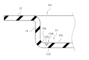
図8はこの形態に係る包装容器が有する裏カバー部材102の拡大図であり、同図では、図4に示す部分に対応する部分が拡大して示されている。図9は図8に示すIX−IX線での断面図である。なお、これらの図において、以上説明した箇所と同一箇所には同一符号を付し、その説明を省略する。
FIG. 8 is an enlarged view of the
図8及び図9に示すように、裏カバー部材102には、裏カバー部材2と同様に、開封部23aが設けられ、開封部23aは開封補助線部123bによって囲まれている。開封補助線部123bには、線状に延伸し溝を呈する凹部123cが形成され、凹部123cには、溝の底を構成する底部123fが設けられている。凹部123cは、開封補助線部123b上において延伸し、開封部23aを取り囲んでいる。例えば、裏カバー部材102に、裏カバー部材2と同様に、2つの開口23gが設けられている場合には、一方の開口23gの2つの隅23jから他方の開口23gの隅23jまで延伸するように、凹部123cは形成される。なお、開封補助線部123bの途中の位置に、裏カバー部材102を貫通するとともに、当該開封補助線部123bの延伸方向に長い切り込みが形成されてもよい。
As shown in FIGS. 8 and 9, the
図10はこのような切り込みを示すための裏カバー部材102の断面図であり、開封補助線部123bに沿って裏カバー部材102を切断した状態が示されている。同図に示す開封補助線部123bには、裏カバー部材102を貫通する切り込み123dが形成され、当該切り込み123dは溝状の凹部123cの途中に位置している。このような切り込み123dは、例えば、開封部23aの角の外周縁に設けられる。例えば、図2に示したように後壁部23の対角線上に2つの開口23gが形成されている場合には、切り込み123dは、そのような開口23gが形成されていない2つの角23mに沿って設けられる。このような位置に切り込み123dを設けることによって、包装容器1の開封時に、開封補助線部123bの破断が、開封部23aの角の位置で止まることを抑制でき、包装容器1の開封作業が容易になる。また、切り込み123dは、開封補助線部123bにおける、直線状に設けられる部分に形成されてもよい。また、このような切り込み123dが、開封補助線部123bにおいて断続的に設けられてもよい。
FIG. 10 is a cross-sectional view of the
また、以上説明した開封補助線部23bに形成された複数の凹部23cは、裏カバー部材2を貫通することなく、各凹部23cに底部23fが設けられていた。しかしながら、開封補助線部23bには、裏カバー部材2を貫通し、裏カバー部材2の表面を凹ませる複数の穴(以下、貫通穴)が、開封補助線部23bの延伸方向に並ぶよう形成されてもよい。この場合、開封補助線部23bには、複数の貫通穴が点線状に形成され、隣接する二つの貫通穴の間隔は、凹部23cの間隔Iと同様に、裏カバー部材2の厚さより小さいことが望ましい。また、この様な貫通穴は、開封補助線部23bの端部(開口23gに近い部分)に形成され、それ以外の部分には凹部23cが形成されてもよい。
Further, the plurality of
また、開封補助線部23bには、このような貫通穴と凹部23cの双方が形成されてもよい。図11は、このような形態に係る裏カバー部材202の断面図であり、当該裏カバー部材202に設けられた開封補助線部223bに沿って裏カバー部材202を切断した状態が示されている。同図に示す開封補助線部223bには、裏カバー部材2を貫通し、裏カバー部材2の表面を凹ませる複数の貫通穴223dが形成されている。そして、貫通穴223dと、凹部23cは、開封補助線部223bにおいて混在するように開封補助線部223bの延伸方向に並んでいる。特に、同図に示す開封補助線部223bでは、凹部23cと貫通穴223dとが交互に設けられている。
Moreover, both such a through hole and the recessed
また、以上説明した包装容器1では、表カバー部材3に、物品を収容可能な収容凹部31が設けられていた。しかしながら、裏カバー部材2に物品を収容可能な収容凹部が設けられ、当該収容凹部に開封補助線部が設けられてもよい。図12は、この形態に係る包装容器300の分解斜視図であり、図13は図12に示す破線XIIIで囲まれた部分の拡大図である。
Moreover, in the
図12に示すように、包装容器300は裏カバー部材302と、表カバー部材303とを有している。表カバー部材303が略板状に形成される一方で、裏カバー部材302は、その外周縁に設けられた四角い枠状のフランジ部322の内側に、物品を収容可能な収容凹部321を有している。収容凹部321は、表カバー部材303と向き合う板状の後壁部323を有している。後壁部323は、裏カバー部材302と表カバー部材303とが張り合わされた後に収容凹部321の内側に構成される収容室を覆うよう設けられている。また、収容凹部321は、後壁部323の外周縁323eから表カバー部材3に向かって垂下する側壁部324を有している。側壁部324は、裏カバー部材302と表カバー部材303とが張り合わされた後には、上記収容室を囲む。
As shown in FIG. 12, the
図13に示すように、包装容器300では、収容凹部321を構成する後壁部323の外周縁323eに沿って、開封補助線部323bが設けられている。そして、外周縁323eの内側には、開封補助線部323bによって囲まれる開封部323aが設けられている。開封補助線部323bには、点線状に設けられる複数の凹部323cが形成され、当該凹部323cは開封部323aを囲んでいる。なお、開封補助線部323bには、この凹部323cとともに、或いは、凹部323cに替えて、貫通穴が形成されてもよい。
As shown in FIG. 13, in the
後壁部323には、フランジ部322に向かって張り出す張り出し部323fが設けられている(図12参照)。また、側壁部324は、その一部に、張り出し部323fの縁323gから垂下する、張り出し壁部324aを有している。そして、開封補助線部23bにおける、張り出し部323fの縁323gに沿う部分には、裏カバー部材302を貫通する切り込み323dが形成されている。この切り込み323dは、縁323gに沿って湾曲しており、当該縁323gに近接している。そのため、包装容器300の開封時に、作業者が張り出し壁部324aを押すと、当該張り出し壁部324aが内側に撓み、作業者は張り出し部323fにおける切り込み323gより内側の部分を摘むことができる。そして、作業者が張り出し部323fを引っ張ると、開封補助線部323bが漸次破断し、開封部323aを開くことができる。なお、開封補助線部323bにおいて切り込み323gに近い部分には、凹部323cに替えて貫通穴が形成されてもよい。これによって、作業者が張り出し部323fの引っ張りを開始した時に、開封補助線部323bが破断し易くなり、さらに開封作業を簡素化できる。また、開封補助線部323bは、後壁部323の外周縁323eと張り出し部323fの縁323gとに近接しており、後壁部323の大部分が開封部323aとなっている。そのため、作業者は容易に収容凹部321の内側に配置されている物品を取り出すことができる。
The
また、以上説明した包装容器1では、裏カバー部材2に開封補助線部23bと当該開封補助線部23bによって囲まれる開封部23aが設けられていた。しかしながら、開封補助線部と開封部は、表カバー部材3に設けられてもよい。
Further, in the
1,300 包装容器、2,102,202,302 裏カバー部材、3,303 表カバー部材、4 パネル、4a 外周縁、10 収容室、22 フランジ部、23,323 後壁部、23a,323a 開封部、23b,123b,223b,323b 開封補助線部、23c,323c,123c 凹部、23d 仕切り部、23e,323g 外周縁、23f 底部、23g 開口、23h 摘み部、31,321 収容凹部、32 フランジ部、223d 穴(貫通穴)、324 側壁部。
1,300 Packaging container, 2,102,202,302 Back cover member, 3,303 Front cover member, 4 panel, 4a outer periphery, 10 receiving chamber, 22 flange portion, 23,323 Rear wall portion, 23a, 323a Open Part, 23b, 123b, 223b, 323b Opening auxiliary line part, 23c, 323c, 123c Recessed part, 23d Partition part, 23e, 323g Outer peripheral edge, 23f Bottom part, 23g Opening, 23h Knob part, 31,321 Receiving concave part, 32
Claims (9)
前記一対のカバー部材のうち少なくとも一方は、シート状のプラスチックによって一体的に成型され、
前記一方のカバー部材は、前記収容室に面する当該一方のカバー部材の一部に、線状に設けられた開封補助線部によって囲まれ、前記包装容器の開封時に前記開封補助線部が破断することによって開く開封部を有し、
前記一方のカバー部材は、その表面が前記開封補助線部において凹むように形成されている、
ことを特徴とする包装容器。 A packaging container comprising a pair of cover members that are attached to each other and constitute a storage chamber capable of storing articles inside thereof,
At least one of the pair of cover members is integrally molded with sheet-like plastic,
The one cover member is surrounded by an opening assisting line portion provided linearly in a part of the one cover member facing the storage chamber, and the opening assisting line portion is broken when the packaging container is opened. Has an opening that opens by
The one cover member is formed such that its surface is recessed in the opening assisting line portion,
A packaging container characterized by that.
前記開封補助線部には、前記一方のカバー部材の前記表面を凹ませる凹部が形成されている、
ことを特徴とする包装容器。 The packaging container according to claim 1,
The opening assisting line portion is formed with a recess for recessing the surface of the one cover member.
A packaging container characterized by that.
前記開封補助線部に、当該開封補助線部の延伸方向に並ぶ複数の前記凹部が形成されている、
ことを特徴とする包装容器。 The packaging container according to claim 2,
A plurality of the recesses arranged in the extending direction of the opening assisting line part is formed in the opening assisting line part,
A packaging container characterized by that.
前記凹部は前記開封補助線部の延伸方向に伸びる溝を呈している、
ことを特徴とする包装容器。 In the packaging container according to claim 2 or 3,
The concave portion presents a groove extending in the extending direction of the opening assisting line portion,
A packaging container characterized by that.
前記開封補助線部には、前記一方のカバー部材を貫通し、当該一方のカバー部材の前記表面を凹ませる複数の穴が形成され、
前記複数の凹部と前記複数の穴は、前記開封補助線部において混在するように当該開封補助線部の延伸方向に並んでいる、
ことを特徴とする包装容器。 The packaging container according to claim 3,
The opening assisting line portion is formed with a plurality of holes that penetrate the one cover member and dent the surface of the one cover member,
The plurality of recesses and the plurality of holes are arranged in the extending direction of the opening assisting line part so as to be mixed in the opening assisting line part,
A packaging container characterized by that.
隣接する2つの前記凹部の間隔は、前記カバー部材の厚さより小さい、
ことを特徴とする包装容器。 The packaging container according to claim 3,
The interval between two adjacent recesses is smaller than the thickness of the cover member,
A packaging container characterized by that.
前記一方のカバー部材には開口が形成され、
前記開封補助線部は前記開口の縁から延伸して前記開封部を囲んでいる、
ことを特徴とする包装容器。 The packaging container according to claim 1,
An opening is formed in the one cover member,
The opening assisting line portion extends from the edge of the opening and surrounds the opening portion,
A packaging container characterized by that.
前記開封補助線部の端部には切り込みが形成され、当該切り込みが前記開口に連なっている、
ことを特徴とする包装容器。 The packaging container according to claim 7,
A cut is formed at an end of the opening assisting line portion, and the cut is continuous with the opening.
A packaging container characterized by that.
前記包装容器は、当該包装容器の内側に、湾曲可能に形成されるとともに前記開封部に沿って配置されるパネルを有し、
前記パネルは、その外周縁が前記開封補助線部に沿って延伸するよう配置されるとともに、前記開封部より大きい、
ことを特徴とする包装容器。
The packaging container according to claim 1,
The packaging container has a panel formed inside the packaging container so as to be bendable and arranged along the opening portion,
The panel is arranged so that an outer peripheral edge thereof extends along the opening assisting line portion, and is larger than the opening portion.
A packaging container characterized by that.
Priority Applications (3)
| Application Number | Priority Date | Filing Date | Title |
|---|---|---|---|
| JP2008320269A JP5519147B2 (en) | 2008-12-16 | 2008-12-16 | Packaging container |
| CN200910151321.0A CN101746559B (en) | 2008-12-16 | 2009-06-30 | Packaging container |
| US12/541,520 US8418878B2 (en) | 2008-12-16 | 2009-08-14 | Packaging container |
Applications Claiming Priority (1)
| Application Number | Priority Date | Filing Date | Title |
|---|---|---|---|
| JP2008320269A JP5519147B2 (en) | 2008-12-16 | 2008-12-16 | Packaging container |
Publications (2)
| Publication Number | Publication Date |
|---|---|
| JP2010143592A true JP2010143592A (en) | 2010-07-01 |
| JP5519147B2 JP5519147B2 (en) | 2014-06-11 |
Family
ID=42239294
Family Applications (1)
| Application Number | Title | Priority Date | Filing Date |
|---|---|---|---|
| JP2008320269A Active JP5519147B2 (en) | 2008-12-16 | 2008-12-16 | Packaging container |
Country Status (3)
| Country | Link |
|---|---|
| US (1) | US8418878B2 (en) |
| JP (1) | JP5519147B2 (en) |
| CN (1) | CN101746559B (en) |
Families Citing this family (1)
| Publication number | Priority date | Publication date | Assignee | Title |
|---|---|---|---|---|
| CN107826464A (en) * | 2010-12-13 | 2018-03-23 | 高露洁-棕榄公司 | Easily demonstration package is opened for commodity |
Citations (10)
| Publication number | Priority date | Publication date | Assignee | Title |
|---|---|---|---|---|
| JPS574164U (en) * | 1980-06-06 | 1982-01-09 | ||
| JPH04106255U (en) * | 1991-02-18 | 1992-09-14 | 大日本印刷株式会社 | airtight container |
| JPH063826U (en) * | 1992-06-22 | 1994-01-18 | 十條セントラル株式会社 | Container |
| JPH0699970A (en) * | 1992-09-25 | 1994-04-12 | Takehiko Abe | Cotton puff packing container |
| JP2002096863A (en) * | 2000-09-21 | 2002-04-02 | Fuji Seal Inc | Container with lid |
| JP2002211647A (en) * | 2001-01-12 | 2002-07-31 | Risu Pack Co Ltd | Packaging container |
| JP2003040352A (en) * | 2001-07-30 | 2003-02-13 | Dainippon Printing Co Ltd | Container |
| JP2003231543A (en) * | 2002-02-07 | 2003-08-19 | Koichi Ishimoto | Packaging container for sealing coagulated body |
| JP2005212811A (en) * | 2004-01-28 | 2005-08-11 | Dainippon Printing Co Ltd | Blister package |
| JP2006256256A (en) * | 2005-03-18 | 2006-09-28 | Mitsubishi Plastics Ind Ltd | Coextruded film for lid of distribution package |
Family Cites Families (9)
| Publication number | Priority date | Publication date | Assignee | Title |
|---|---|---|---|---|
| FR1464910A (en) * | 1965-11-26 | 1967-01-06 | Packaging improvements | |
| US5007231A (en) * | 1985-08-16 | 1991-04-16 | Plm Ab | Container |
| US4990345A (en) * | 1988-12-05 | 1991-02-05 | Webb John D | Package with compartmented closure assembly |
| JP2001097444A (en) | 1999-09-30 | 2001-04-10 | Sony Corp | Clamshell package |
| JP4519999B2 (en) * | 2000-07-25 | 2010-08-04 | エフピコチュ−パ株式会社 | Packaging container |
| CN1406821A (en) * | 2001-09-10 | 2003-04-02 | 陈瑞发 | Draw-free ring style packing tin |
| AT500343B1 (en) * | 2004-04-15 | 2007-03-15 | Teich Ag | LID WITH REMOVAL OPENING FOR CLOSING CONTAINERS |
| WO2007018300A1 (en) * | 2005-08-09 | 2007-02-15 | Fujimura Kogyo Co., Ltd. | Easily unsealable sealing container |
| CN100509583C (en) * | 2006-04-19 | 2009-07-08 | 智易科技股份有限公司 | Plastic packing box |
-
2008
- 2008-12-16 JP JP2008320269A patent/JP5519147B2/en active Active
-
2009
- 2009-06-30 CN CN200910151321.0A patent/CN101746559B/en active Active
- 2009-08-14 US US12/541,520 patent/US8418878B2/en active Active
Patent Citations (10)
| Publication number | Priority date | Publication date | Assignee | Title |
|---|---|---|---|---|
| JPS574164U (en) * | 1980-06-06 | 1982-01-09 | ||
| JPH04106255U (en) * | 1991-02-18 | 1992-09-14 | 大日本印刷株式会社 | airtight container |
| JPH063826U (en) * | 1992-06-22 | 1994-01-18 | 十條セントラル株式会社 | Container |
| JPH0699970A (en) * | 1992-09-25 | 1994-04-12 | Takehiko Abe | Cotton puff packing container |
| JP2002096863A (en) * | 2000-09-21 | 2002-04-02 | Fuji Seal Inc | Container with lid |
| JP2002211647A (en) * | 2001-01-12 | 2002-07-31 | Risu Pack Co Ltd | Packaging container |
| JP2003040352A (en) * | 2001-07-30 | 2003-02-13 | Dainippon Printing Co Ltd | Container |
| JP2003231543A (en) * | 2002-02-07 | 2003-08-19 | Koichi Ishimoto | Packaging container for sealing coagulated body |
| JP2005212811A (en) * | 2004-01-28 | 2005-08-11 | Dainippon Printing Co Ltd | Blister package |
| JP2006256256A (en) * | 2005-03-18 | 2006-09-28 | Mitsubishi Plastics Ind Ltd | Coextruded film for lid of distribution package |
Also Published As
| Publication number | Publication date |
|---|---|
| CN101746559A (en) | 2010-06-23 |
| CN101746559B (en) | 2013-01-16 |
| JP5519147B2 (en) | 2014-06-11 |
| US20100147852A1 (en) | 2010-06-17 |
| US8418878B2 (en) | 2013-04-16 |
Similar Documents
| Publication | Publication Date | Title |
|---|---|---|
| JP5519147B2 (en) | Packaging container | |
| CN107074424B (en) | Clamshell container with toothed side perforations | |
| EP3564150B1 (en) | Battery packaging body | |
| JP7107098B2 (en) | packaging box | |
| EP2557046B1 (en) | Packing case | |
| RU2522091C2 (en) | Blister package having tear-off weakened area | |
| JP3218331U (en) | Box sheet | |
| JP6273129B2 (en) | Airtight container and airtight container set | |
| JP4687580B2 (en) | Repack blister | |
| JP7133296B2 (en) | packaging box | |
| JP2017159913A (en) | Packaging bag | |
| JP7409962B2 (en) | packaging box | |
| JP6295989B2 (en) | Packing box | |
| JP3190696U (en) | Packaging box | |
| JP5728286B2 (en) | Packaging box with handle | |
| JP2019011070A (en) | Storage box | |
| JP5103303B2 (en) | Sealed container | |
| JP2000203553A (en) | Container | |
| JP2003160127A (en) | Goods storage container | |
| JP6877934B2 (en) | Package | |
| JP2008290436A (en) | Document storage case | |
| JP2007275339A (en) | Exothermic container for heating food | |
| JP7603365B2 (en) | Container and lidded container using the same | |
| JP2001163359A (en) | Packaging container | |
| JP2006051962A (en) | Tissue paper box |
Legal Events
| Date | Code | Title | Description |
|---|---|---|---|
| A711 | Notification of change in applicant |
Free format text: JAPANESE INTERMEDIATE CODE: A712 Effective date: 20101124 |
|
| RD02 | Notification of acceptance of power of attorney |
Free format text: JAPANESE INTERMEDIATE CODE: A7422 Effective date: 20101203 |
|
| A621 | Written request for application examination |
Free format text: JAPANESE INTERMEDIATE CODE: A621 Effective date: 20111213 |
|
| A977 | Report on retrieval |
Free format text: JAPANESE INTERMEDIATE CODE: A971007 Effective date: 20130201 |
|
| A131 | Notification of reasons for refusal |
Free format text: JAPANESE INTERMEDIATE CODE: A131 Effective date: 20130219 |
|
| A521 | Request for written amendment filed |
Free format text: JAPANESE INTERMEDIATE CODE: A523 Effective date: 20130422 |
|
| A131 | Notification of reasons for refusal |
Free format text: JAPANESE INTERMEDIATE CODE: A131 Effective date: 20130813 |
|
| A521 | Request for written amendment filed |
Free format text: JAPANESE INTERMEDIATE CODE: A523 Effective date: 20131015 |
|
| TRDD | Decision of grant or rejection written | ||
| A01 | Written decision to grant a patent or to grant a registration (utility model) |
Free format text: JAPANESE INTERMEDIATE CODE: A01 Effective date: 20140304 |
|
| A61 | First payment of annual fees (during grant procedure) |
Free format text: JAPANESE INTERMEDIATE CODE: A61 Effective date: 20140403 |
|
| R150 | Certificate of patent or registration of utility model |
Ref document number: 5519147 Country of ref document: JP Free format text: JAPANESE INTERMEDIATE CODE: R150 |
|
| R250 | Receipt of annual fees |
Free format text: JAPANESE INTERMEDIATE CODE: R250 |
|
| R250 | Receipt of annual fees |
Free format text: JAPANESE INTERMEDIATE CODE: R250 |
|
| R250 | Receipt of annual fees |
Free format text: JAPANESE INTERMEDIATE CODE: R250 |
|
| R250 | Receipt of annual fees |
Free format text: JAPANESE INTERMEDIATE CODE: R250 |
|
| R250 | Receipt of annual fees |
Free format text: JAPANESE INTERMEDIATE CODE: R250 |
|
| R250 | Receipt of annual fees |
Free format text: JAPANESE INTERMEDIATE CODE: R250 |