JP2010143593A - Packaging box - Google Patents
Packaging box Download PDFInfo
- Publication number
- JP2010143593A JP2010143593A JP2008320555A JP2008320555A JP2010143593A JP 2010143593 A JP2010143593 A JP 2010143593A JP 2008320555 A JP2008320555 A JP 2008320555A JP 2008320555 A JP2008320555 A JP 2008320555A JP 2010143593 A JP2010143593 A JP 2010143593A
- Authority
- JP
- Japan
- Prior art keywords
- side wall
- lid
- wall portion
- lid body
- packaging box
- Prior art date
- Legal status (The legal status is an assumption and is not a legal conclusion. Google has not performed a legal analysis and makes no representation as to the accuracy of the status listed.)
- Pending
Links
- 238000004806 packaging method and process Methods 0.000 title claims abstract description 45
- 239000000463 material Substances 0.000 claims abstract description 28
- 230000002093 peripheral effect Effects 0.000 claims description 52
- 230000000694 effects Effects 0.000 description 3
- 238000005452 bending Methods 0.000 description 2
- 235000013305 food Nutrition 0.000 description 2
- 238000004080 punching Methods 0.000 description 2
- 239000000853 adhesive Substances 0.000 description 1
- 230000001070 adhesive effect Effects 0.000 description 1
- 125000004122 cyclic group Chemical group 0.000 description 1
- 230000037431 insertion Effects 0.000 description 1
- 238000003780 insertion Methods 0.000 description 1
- 239000011347 resin Substances 0.000 description 1
- 229920005989 resin Polymers 0.000 description 1
Images
Landscapes
- Cartons (AREA)
- Packages (AREA)
- Closures For Containers (AREA)
Abstract
Description
本発明は、食品や日用品、その他物品を包装するための包装箱に関し、より詳しくは、環状に形成された側壁部及び該側壁部の下端部開口を閉塞した底部を有する箱本体と、側壁部の上端部開口を閉塞可能に構成された蓋体とを備えた包装箱に関する。 The present invention relates to a packaging box for packaging food, daily necessities, and other articles. More specifically, the present invention relates to a box body having a side wall portion formed in an annular shape and a bottom portion closing a lower end opening of the side wall portion, and a side wall portion. It is related with the packaging box provided with the cover body comprised so that obstruction | occlusion of the upper-end part opening of this was possible.
従来から、食品や日用品等の物品を包装するための包装箱として、種々のものが提供されており、その一つとして、環状に形成された側壁部及び該側壁部の下端部開口を閉塞した底部を有する箱本体と、側壁部の上端部開口を閉塞可能に構成された蓋体とを備え、側壁部内に物品を収容した状態で蓋体を箱本体(側壁部)に外嵌して側壁部の上端部開口を閉塞するようにした、いわゆる、印籠式の包装箱が周知である。 Conventionally, various types of packaging boxes for packaging articles such as foods and daily necessities have been provided. As one of them, the annularly formed side wall and the lower end opening of the side wall are closed. A box body having a bottom portion and a lid body configured to be able to close an upper end opening of the side wall portion, and the side wall is formed by externally fitting the lid body to the box body (side wall portion) in a state where an article is accommodated in the side wall portion. A so-called stamping type packaging box which closes the upper end opening of the part is well known.
そして、この種の包装箱は、箱本体の側壁部に蓋体を外嵌するようになっているため、側壁部と蓋体の外周との間に段差ができ、見栄えがよくないとして、蓋体の外周面と側壁部の外周面とが面一になるようにしたものも提供されている(例えば、特許文献1参照)。 And since this kind of packaging box is adapted to externally fit the lid body to the side wall portion of the box body, there is a step between the side wall portion and the outer periphery of the lid body. There is also provided an apparatus in which the outer peripheral surface of the body and the outer peripheral surface of the side wall portion are flush with each other (see, for example, Patent Document 1).
かかる包装箱の箱本体は、上部が開放した外箱に内枠又は内箱が内装されており、内枠又は内箱の上端部が外箱の上端から上方に延出している。これにより、かかる包装箱は、側壁部の上端部に段差が形成されており、側壁部の上端部に蓋体を外嵌した状態で蓋体の外周面と側壁部の外周面とが面一になるようになっている。従って、かかる包装箱は、外観がすっきりして見栄えがよいとして、贈答品等を包装する場合等に多用されている。
ところで、上記構成の包装箱は、外観が見栄え良く構成されているが、単に蓋体を箱本体に外嵌するだけであるため、箱本体から蓋体が不用意に外れるといった問題がある。特に、箱本体(側壁部)の上下方向の高さが低く設定される場合には、側壁部に対して蓋体を外嵌できる領域(側壁部に対する蓋体の重なり)を十分に確保できなくなるため、箱本体から蓋体が脱落する可能性が高まってしまう。 By the way, although the packaging box of the said structure is comprised with the external appearance, it has the problem that a cover body removes carelessly from a box main body only because a cover body is only externally fitted to a box main body. In particular, when the height of the box body (side wall portion) in the vertical direction is set low, it is not possible to sufficiently secure a region in which the lid body can be externally fitted to the side wall portion (overlap of the lid body with respect to the side wall portion). For this reason, the possibility that the lid body falls off from the box body is increased.
そこで、本発明は、外観の見栄えを良好にすることができる上に、物品を収容する箱本体の高さに関係なく、蓋体が不用意に外れるのを確実に防止することのできる包装箱を提供することを課題とする。 Therefore, the present invention can improve the appearance of the appearance and can reliably prevent the lid from being inadvertently removed regardless of the height of the box body that accommodates the article. It is an issue to provide.
本発明に係る包装箱は、環状に形成された側壁部及び該側壁部の下端部開口を閉塞した底部を有する箱本体と、側壁部の上端部開口を閉塞可能に構成された蓋体とを備えた包装箱において、前記箱本体は、側壁部の上端部内周の全周又は複数箇所から内側に突出した上端突出部と、該上端突出部よりも下方位置で側壁部の内周の全周又は複数箇所から内側に延出した内部延出部とを備え、前記蓋体は、側壁部の上端部開口を閉塞可能に形成され、少なくとも外周縁部が変形可能なシート材で構成された蓋本体部と、該蓋本体部の上面側に延出した摘持部とを備え、前記蓋本体部は、外周縁部が側壁部内で内部延出部上に載置可能で且つ上端突出部に対向可能に形成されていることを特徴とする。 A packaging box according to the present invention comprises a box body having a side wall portion formed in an annular shape and a bottom portion that closes a lower end opening of the side wall portion, and a lid configured to be able to close an upper end opening of the side wall portion. In the packaging box provided, the box main body has an upper end protrusion that protrudes inward from the entire periphery of the upper end portion of the side wall portion or a plurality of locations, and an entire periphery of the inner periphery of the side wall portion at a position lower than the upper end protrusion portion. Or an internal extension portion extending inward from a plurality of locations, wherein the lid body is formed so as to be able to close the upper end opening of the side wall portion, and at least the outer peripheral edge portion is made of a sheet material that can be deformed. A main body portion and a gripping portion extending to the upper surface side of the lid main body portion, and the lid main body portion has an outer peripheral edge portion that can be placed on the inner extension portion within the side wall portion, and is formed on the upper end protruding portion. It is formed so that it can oppose.
上記構成の包装箱によれば、蓋体を箱本体(側壁部)の上端部開口に押し込むようにすると、蓋本体部の外周縁部が変形しつつ上端突出部を乗り越えた後に内部延出部上に載置され、側壁部の上端部開口が閉塞される。このように、蓋本体部が側壁部内で内部延出部上に載置されると、包装箱(箱本体)の外周上に蓋体が存在しないため、蓋体の存在で外周に段差等が形成されることがなく、見栄え良くまた斬新な態様になる。 According to the packaging box having the above configuration, when the lid is pushed into the upper end opening of the box main body (side wall portion), the outer peripheral edge of the lid main body is deformed and the inner extension portion is moved over the upper end protruding portion. The upper end opening of the side wall is closed. In this way, when the lid body is placed on the internal extension within the side wall, there is no lid on the outer periphery of the packaging box (box body), so there is a step or the like on the outer periphery due to the presence of the lid. It is not formed, and it looks nice and innovative.
そして、蓋体が箱本体の上端部開口を閉塞した状態で、蓋体が上方に移動しようとすると、蓋本体部の外周縁部が上方側で対向する上端突出部に係止され、当該蓋体が不用意に外れることが防止される。このように、上記構成の包装箱は、従来の印籠式の包装箱のように、箱本体に対する蓋体の重なり量、すなわち、箱本体(側壁部)の上下方向の高さに影響を受けることがなく、蓋体が不用意に外れるのを確実に防止することができる。そして、上記構成の包装箱は、使用者が摘持部を持って意図的に蓋体を引き上げると、蓋本体部の外周縁部が変形しつつ上端突出部を乗り越えることになり、蓋体を取り外すことができる。 Then, when the lid attempts to move upward in a state where the upper end opening of the box body is closed, the outer peripheral edge of the lid main body is locked to the upper end protruding portion facing upward, and the lid Inadvertent removal of the body is prevented. Thus, the packaging box having the above configuration is affected by the amount of overlap of the lid body with respect to the box body, that is, the vertical height of the box body (side wall portion), as in the case of the conventional Inba type packaging box. Therefore, it is possible to reliably prevent the lid from being inadvertently detached. When the user holds the gripping part and intentionally lifts the lid, the outer peripheral edge of the lid body part is deformed and the packaging box having the above structure gets over the upper end protruding part. Can be removed.
本発明の一態様として、前記上端突出部は、側壁部の上端部を内側にカールすることで形成されてもよい。このようにすれば、側壁部と上端突出部とが一体的に形成されるため、蓋体を着脱するとき(蓋本体部の外周縁部が上端突出部を乗りえるとき)に生じる力に十分に耐え得る強度を得ることができる。 As one aspect of the present invention, the upper end protruding portion may be formed by curling the upper end portion of the side wall portion inward. In this way, the side wall portion and the upper end protruding portion are integrally formed, so that it is sufficient for the force generated when the lid body is attached and detached (when the outer peripheral edge portion of the lid main body can ride on the upper end protruding portion). It is possible to obtain a strength that can withstand.
本発明の他態様として、前記上端突出部及び内部延出部は、側壁部の内周の全周に亘って設けられてもよい。このようにすれば、蓋体で側壁部の上端部開口を閉塞したときに蓋本体部の外周縁部の全周が内部延出部に受けられることになり安定した装着が可能となる。また、蓋体が上方に移動しようとしたときに蓋本体部の外周縁部の全周が上端突出部に受けられることになり、蓋体の脱落を確実に防止することができる。 As another aspect of the present invention, the upper end protrusion and the internal extension may be provided over the entire inner periphery of the side wall. In this way, when the upper end opening of the side wall portion is closed with the lid, the entire periphery of the outer peripheral edge of the lid body is received by the internal extension, and stable mounting is possible. Further, when the lid is about to move upward, the entire periphery of the outer peripheral edge of the lid body is received by the upper end protruding portion, and the lid can be reliably prevented from falling off.
さらに、本発明の別の態様として、前記内部延出部は、側壁部の上端部開口を蓋体で閉塞した状態で、蓋本体部の外周縁部を上端突出部とともに挟み込めるように配置されてもよい。このようにすれば、蓋体で側壁部の上端部開口を閉塞した状態で、蓋体が上下方向に移動することがないため、蓋体を安定した状態で取り付けることができ見栄えをより良好にすることができる。 Furthermore, as another aspect of the present invention, the internal extension portion is arranged so as to sandwich the outer peripheral edge portion of the lid main body portion together with the upper end protruding portion in a state where the upper end opening of the side wall portion is closed by the lid body. May be. In this way, since the lid body does not move in the vertical direction with the upper end opening of the side wall portion closed with the lid body, the lid body can be attached in a stable state and the appearance is improved. can do.
以上のように、本発明に係る包装箱は、外観の見栄えを良好にすることができる上に、物品を収容する箱本体の高さに関係なく、蓋体が不用意に外れるのを確実に防止することができるといった優れた効果を奏し得る。 As described above, the packaging box according to the present invention can improve the appearance and ensure that the lid is inadvertently removed regardless of the height of the box body that houses the article. An excellent effect that it can be prevented can be obtained.
以下、本発明の一実施形態に係る包装箱について、添付図面を参照しつつ説明する。 Hereinafter, a packaging box according to an embodiment of the present invention will be described with reference to the accompanying drawings.
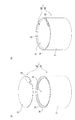
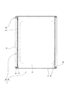
本実施形態に係る包装箱は、図1及び図2に示す如く、環状に形成された側壁部11及び該側壁部11の下端部開口を閉塞した底部12を有する箱本体10と、側壁部11の上端部開口Hを閉塞可能に構成された蓋体20とを備えている。
As shown in FIGS. 1 and 2, the packaging box according to the present embodiment includes a
前記箱本体10は、側壁部11が包装形態に応じて角環状或いは円環状に形成される。すなわち、側壁部11は、角筒状又は円筒状に形成されるもので、本実施形態においては、円筒状(円環状)に形成されている。該側壁部11は、シート状の材料(本実施形態においては紙材料(厚紙))を環状に曲げ加工して形成されている。本実施形態に係る側壁部11は、上述の如く、円環状(円筒状)に形成されるため、矩形状のシート材を円筒状に丸め(曲げ)、重なり合った両端同士を接着剤等で接合することによって形成されている。そして、側壁部11は、外周面に所定の印刷が施されたり、所定の色彩や、模様等が施された和紙等の化粧紙が貼り付けられたりすることで装飾されている。
As for the said box
そして、本実施形態に係る箱本体10は、図1(a)及び図2に示す如く、側壁部11の上端内周の全周から内側に突出した上端突出部13と、該上端突出部13の下方位置で側壁部11の内周の全周から内側に延出した内部延出部14とを備えている。
As shown in FIGS. 1A and 2, the
前記上端突出部13は、側壁部11内に対する物品Pの出し入れを阻害しない程度で側壁部11の内側に向かって突出している。本実施形態に係る上端突出部13は、側壁部11の上端部を内側にカールすることで形成されている。すなわち、本実施形態に係る箱本体10は、側壁部11が紙材料(厚紙)で構成されているため、該側壁部11を構成する紙材料を丸め加工(カール加工)することで、上端突出部13が側壁部11と一体的に形成されている。
The upper
前記内部延出部14は、平面視において無端環状に形成されており、側壁部11内に対して物品Pを出し入れする出入口を画定している。本実施形態に係る内部延出部14は、側壁部11を構成するシート材とは別のシート材を平面視において環状(ドーナツ状)に切断加工(又は打ち抜き加工)して形成したもので、その外周が側壁部11の内周面に対して接着されている。これにより、内部延出部14は、側壁部11の内周全周から内側(側壁部11の中央)に向けて延出した状態になっている。
The
そして、該内部延出部14は、上端突出部13との間に蓋体20(後述する蓋本体部21)の外周縁部を介在し得る間隙を形成した位置に配置されている。本実施形態に係る内部延出部14は、上端突出部13との間隔が蓋体20の外周縁部の厚みと同一又は略同一の間隔になるように配置されている。すなわち、内部延出部14は、上端突出部13とともに蓋体20の外周縁部を挟み込める位置に配置されている。
The
そして、内部延出部14は、上述の如く、物品Pの出入口を画定するため、物品Pの出し入れを阻害せず、且つ、蓋体20(後述する蓋本体部21)の外周縁部を受けることができる延出量に設定される。例えば、上端突出部13をカール加工によって形成する場合、側壁部11の内周面を基準に、上端突出部13の突出量以上で該上端突出部13の突出量の五倍以下、好ましくは、上端突出部13の突出量以上で該上端突出部13の突出量の三倍以下に設定される。
As described above, the
そして、前記側壁部11は、図2に示す如く、下端部に底部12を受ける底受部15が形成されている。かかる底受部15は、側壁部11の内側に向かって突出するように形成されている。本実施形態に係る底受部15は、上端突出部13と同様に、側壁部11を構成する前記紙材料を丸め加工(カール加工)することで、側壁部11と一体的に形成されている。
And as shown in FIG. 2, the said
前記底部12は、側壁部11の内形状に対応するようにシート材を切断加工(或いは打ち抜き加工)することで形成されている。そして、該底部12は、側壁部11内で外周縁部が底受部15に載置された状態で、側壁部11及び底受部15の少なくとも何れか一方に接着されて固定されている。
The bottom 12 is formed by cutting (or punching) a sheet material so as to correspond to the inner shape of the
前記蓋体20は、側壁部11の上端部開口Hを閉塞可能に形成され、少なくとも外周縁部が変形可能なシート材で構成された蓋本体部21と、該蓋本体部21の上面側に延出した摘持部22とを備えている。
The
本実施形態に係る蓋本体部21は、全体が紙製のシート材(厚紙)で構成されており、外周縁部のみならず全体が変形できるようになっている。そして、蓋本体部21は、外周縁部が側壁部11内で内部延出部14上に載置可能で且つ上端突出部13に対向可能に形成されている。本実施形態においては、側壁部11が円筒状に形成されているため、蓋本体部21は、円板状に形成されている。そして、該蓋本体部21は、外径が側壁部11の内径よりも小径で且つ上端突出部13の内径及び内部延出部14の内径よりも大径に設定されている。
The lid
そして、蓋本体部21は、少なくとも一方の面(上面)に所定の印刷が施されたり、所定の色彩や、模様等が施された和紙等の化粧紙が貼り付けられたりすることで、装飾されている。
The
そして、前記摘持部22は、蓋本体部21と一体的に形成されている。すなわち、摘持部22は、蓋本体部21の外周端部の一部を切り起こすことで、蓋本体部21の一方の面(上面)側に延出するように形成されている。
The
本実施形態に係る包装箱1は、以上の構成からなり、次に該包装箱1の使用態様について説明する。
The
まず、箱本体10(側壁部11)内に包装対象となる物品Pを収容し、図1(a)に示す如く、摘持部22が上側に突出するように蓋本体部21の他方の面を下側に向け、蓋体20(蓋本体部21)を箱本体10(側壁部11)の上端部開口Hに押し込む。そうすると、前記蓋本体部21は、外径が上端突出部13よりも大径に設定されているため、外周縁部が変形しつつ上端突出部13を乗り越えることになる。
First, an article P to be packaged is accommodated in the box body 10 (side wall portion 11), and the other surface of the
そして、蓋本体部21は、外周縁部が上端突出部13を乗り越えると、図1(b)及び図2に示す如く、側壁部11内に入り込んで外周縁部が内部延出部14上に載置されるとともに、該外周縁部が上方側にある上端突出部13と対向する。この状態で蓋本体部21は、側壁部11の上端部開口H(上端突出部13が画定する開口領域及び内部延出部14が画定する開口領域)の全域に存在することになり、側壁部11の上端部開口Hが閉塞される。
Then, when the outer peripheral edge gets over the upper
本実施形態においては、上端突出部13と内部延出部14との間隔が蓋本体部21(蓋本体部21の外周縁部)の厚みと同一又は略同一に設定されているため、蓋本体部21が側壁部11の上端部開口Hを閉じた状態、すなわち、蓋本体部21の外周縁部が内部延出部14上に載った状態で、該外周縁部が上端突出部13と内部延出部14とに挟まれた状態になる。これにより、蓋体20は、上下方向の移動が完全に又は略完全に規制された状態になるため、安定した状態で箱本体10に対して装着される。
In the present embodiment, the distance between the
このように、本実施形態に係る包装箱1は、蓋体20が側壁部11の上端部開口Hを閉じた状態では、蓋本体部21が側壁部11内で内部延出部14上に載置されるため、包装箱1(箱本体10)の外周上に蓋体20が露呈しない態様となる。これにより、該包装箱1は、蓋体20の存在で外周に段差等が形成されることがなく、見栄え良くまた斬新な態様で物品Pを包装することができる。
As described above, in the
そして、上述の如く、蓋体20が箱本体10の上端部開口Hを閉塞した状態で、蓋本体部21の外周縁部が上方側にある上端突出部13と対向しているため、例えば、包装箱1を持ち運ぶことで収容した物品Pが動く等して、側壁部11内から蓋体20に対して上方に向けての力(蓋体20を押し上げようとする力)が作用したとき、蓋本体部21の外周縁部が対向する上端突出部13に係止され、当該蓋体20が不用意に外れることが防止される。
And, as described above, with the
これに対し、使用者が意図的に蓋体20の摘持部22を持って蓋体20を引き上げると、蓋本体部21の外周縁部が変形しつつ上端突出部13を乗り越えることになり、蓋体20を取り外すことができる。
On the other hand, when the user intentionally holds the gripping
以上のように、本実施形態に係る包装箱1は、環状に形成された側壁部11及び該側壁部11の下端部開口を閉塞した底部12を有する箱本体10と、側壁部11の上端部開口Hを閉塞可能に構成された蓋体20とを備えた包装箱1において、前記箱本体10は、側壁部11の上端部内周の全周又は複数箇所から内側に突出した上端突出部13と、該上端突出部13よりも下方位置で側壁部11の内周の全周又は複数箇所から内側に延出した内部延出部14とを備え、前記蓋体20は、側壁部11の上端部開口Hを閉塞可能に形成され、少なくとも外周縁部が変形可能なシート材で構成された蓋本体部21と、該蓋本体部21の上面側に延出した摘持部22とを備え、前記蓋本体部21は、外周縁部が側壁部11内で内部延出部14上に載置可能で且つ上端突出部13に対向可能に形成されているので、外観の見栄えを良好にすることができる上に、物品Pを収容する箱本体10の高さに関係なく、蓋体20が不用意に外れるのを確実に防止することができるといった優れた効果を奏し得る。
As described above, the
また、本実施形態に係る包装箱1は、前記上端突出部13が側壁部11の上端部を内側にカールすることで形成されているので、側壁部11と上端突出部13とが一体的に形成され、蓋本体部21の外周縁部が上端突出部13を乗りえる際に生じる力に十分に耐え得る強度を得ることができる。
Moreover, since the said upper
さらに、本実施形態に係る包装箱1は、上端突出部13及び内部延出部14が側壁部11の全周に亘って設けられているので、蓋体20で側壁部11の上端部開口Hを閉塞したときに蓋本体部21の外周縁部の全周が内部延出部14に受けられることになり安定した装着が可能となる。また、蓋体20が上方に移動しようとしたときに蓋本体部21の外周縁部の全周が上端突出部13に受けられることになり、蓋体20の脱落を確実に防止することができる。
Furthermore, the
そして、本実施形態に係る包装箱1は、側壁部11の上端部開口Hを蓋体20で閉塞した状態で、内部延出部14が蓋本体部21の外周縁部を上端突出部13とともに挟み込めるように配置されているので、蓋体20で側壁部11の上端部開口Hを閉塞した状態で、蓋体20が上下方向に移動することがないため、蓋体20を安定した状態で取り付けることができ見栄えをより良好にすることができる。
And the
尚、本発明は、上記実施形態に限定されるものではなく、本発明の要旨を逸脱しない範囲内において種々変更を加え得ることは勿論である。 In addition, this invention is not limited to the said embodiment, Of course, a various change can be added in the range which does not deviate from the summary of this invention.
上記実施形態において、矩形状のシート材を丸めて円筒状の側壁部11を形成するようにしたが、これに限定されるものではなく、例えば、本実施形態のように側壁部11を紙材料で構成するとともに円筒状に形成する場合には、円筒状の紙管を軸線方向で必要長さに切断して側壁部11とするようにしてもよい。
In the above embodiment, the rectangular
上記実施形態において、側壁部11を円筒状に形成したが、側壁部11の形態はこれに限定されるものではなく、例えば、側壁部11を角環状、すなわち、多角筒状(枠状)に形成しても勿論よい。従って、箱本体10は、別部材で構成された側壁部11と底部12とを接続して形成したものに限定されるものではなく、例えば、底部12となる平面視多角形状(主として四角形状)領域を画定する各端縁に側壁部11となる矩形状の領域を延設した展開シートを折り曲げ加工して形成したものであってもよい。この場合においても、側壁部11の上端部に上端突出部13を設け、これの下方位置に内部延出部14を設ければ、上記実施形態と同様の作用及び効果を奏することができる。
In the said embodiment, although the
上記実施形態において、一枚のシート材の一部を切り起こすことで摘持部22を蓋本体部21に対して一体的に形成したが、これに限定されるものではなく、例えば、蓋本体部21の上面に別部材で構成した摘持部22を接続するようにしてもよい。
In the above embodiment, the gripping
上記実施形態において、上端突出部13及び内部延出部14を側壁部11の内周全周に亘って設けるようにした、すなわち、上端突出部13及び内部延出部14を環状(ドーナツ状)に形成するようにしたが、これに限定されるものではなく、例えば、上端突出部13及び内部延出部14の少なくとも何れか一方を側壁部11の周方向で断続的な配置で設けるようにしてもよい。すなわち、上端突出部13を側壁部11の周方向に断続的に(間隔をあけて)複数設ける一方、内部延出部14を上記実施形態と同様に環状に形成するようにしたり、上端突出部13を上記実施形態と同様に環状に形成する一方、内部延出部14を側壁部11の周方向に断続的に(間隔をあけて)複数設けるようにしたりしてもよい。また、上端突出部13及び内部延出部14の両方を側壁部11の周方向に断続的(間隔をあけて)複数設けてもよい。そして、このように上端突出部13及び内部延出部14の両方を側壁部11の周方向に断続的(間隔をあけて)複数設ける場合には、必ずしも両者が対向した配置にしたものに限定されるものではなく、例えば、上端突出部13と内部延出部14とを周方向でずれた配置にしてもよい。
In the said embodiment, the upper
上記実施形態において、側壁部11の上端部(側壁部11を構成するシート材の端部)を丸め加工(カール加工)して上端突出部13を形成するようにしたが、上端突出部13はこれに限定されるものではなく、例えば、内部延出部14と同様に、上端突出部13を側壁部11となるシート材とは別部材で構成し、これを側壁部11に接続することで上端突出部13とするようにしてもよい。また、上端突出部13は、側壁部11の上端縁に形成されたものに限定されるものではなく、例えば、側壁部11の上端縁よりも下方位置に位置するように設けてもよい。すなわち、上端突出部13は外観良好となる範囲内で側壁部11の上端縁よりも奥まった位置に配置されてもよい。
In the above embodiment, the
上記実施形態において、箱本体10及び蓋体20をシート状の紙材(厚紙)から形成するようにしたが、これに限定されるものではなく、例えば、これらの両方、或いは、何れか一方を樹脂製シートで形成するようにしても勿論よい。
In the above embodiment, the
そして、上記実施形態において、蓋体20の蓋本体部21の外周縁部が変形可能となることを前提に該蓋本体部21全体を同一素材で構成するようにしたが、これに限定されるものではなく、例えば、蓋体20本体の外周縁部のみを変形可能な素材(シート材)で構成し、該外周縁部よりも内側に部分を変形不能な素材で構成するようにしてもよい。
In the above embodiment, the
上記実施形態において、側壁部11の上端部開口Hを蓋体20で閉塞したときに、蓋体20(蓋本体部21)の外周縁部が、内部延出部14と上端突出部13とに挟み込まれた態様になるようにしたが、これに限定されるものではなく、例えば、上端突出部13と内部延出部14との間隔を蓋本体部21の外周縁部の厚みよりも広く設定し、側壁部11の上端部開口Hを蓋体20で閉塞したときに蓋本体部21の外周縁部が上端突出部13と内部延出部14とに挟み込まれることなく該内部延出部14上に載った状態になるようにしてもよい。このようにしても、蓋体20が上方側に移動しようとしても蓋本体部21の外周縁部が上端突出部13に係止されるため、蓋体20が不用意に外れてしまうことを防止することができる。但し、蓋体20の装着安定性を考慮すれば、上記実施形態と同様に、蓋本体部21の外周縁部が上端突出部13と内部延出部14とに挟み込まれた態様になるようにすることが好ましい。
In the above embodiment, when the upper end opening H of the
上記実施形態において、箱本体10(側壁部11)の外周面や蓋体20(蓋本体部21)の上面に印刷を施したり化粧紙を貼り付けたりして装飾するようにしたが、これに限定されるものではなく、これらを構成する素材(シート材)そのものを表面に露呈させるようにしても勿論よい。 In the above embodiment, the outer peripheral surface of the box body 10 (side wall portion 11) and the upper surface of the lid body 20 (lid body portion 21) are decorated by printing or attaching decorative paper. Of course, the material (sheet material) constituting these materials may be exposed on the surface.
1…包装箱、10…箱本体、11…側壁部、12…底部、13…上端突出部、14…内部延出部、15…底受部、20…蓋体、21…蓋本体部、22…摘持部、H…上端部開口、P…物品
DESCRIPTION OF
Claims (4)
Priority Applications (1)
| Application Number | Priority Date | Filing Date | Title |
|---|---|---|---|
| JP2008320555A JP2010143593A (en) | 2008-12-17 | 2008-12-17 | Packaging box |
Applications Claiming Priority (1)
| Application Number | Priority Date | Filing Date | Title |
|---|---|---|---|
| JP2008320555A JP2010143593A (en) | 2008-12-17 | 2008-12-17 | Packaging box |
Publications (1)
| Publication Number | Publication Date |
|---|---|
| JP2010143593A true JP2010143593A (en) | 2010-07-01 |
Family
ID=42564438
Family Applications (1)
| Application Number | Title | Priority Date | Filing Date |
|---|---|---|---|
| JP2008320555A Pending JP2010143593A (en) | 2008-12-17 | 2008-12-17 | Packaging box |
Country Status (1)
| Country | Link |
|---|---|
| JP (1) | JP2010143593A (en) |
Cited By (1)
| Publication number | Priority date | Publication date | Assignee | Title |
|---|---|---|---|---|
| CN107839964A (en) * | 2017-12-06 | 2018-03-27 | 何勇辉 | The repeatable button packing case utilized |
Citations (6)
| Publication number | Priority date | Publication date | Assignee | Title |
|---|---|---|---|---|
| JPS5395344U (en) * | 1976-12-30 | 1978-08-03 | ||
| JPS63169413U (en) * | 1987-04-23 | 1988-11-04 | ||
| JPH0256114U (en) * | 1988-10-13 | 1990-04-24 | ||
| JPH02141317U (en) * | 1989-04-28 | 1990-11-28 | ||
| JPH06336241A (en) * | 1993-05-26 | 1994-12-06 | Maeda Kami Shoji Kk | Packaging container |
| JPH0726316U (en) * | 1993-10-14 | 1995-05-16 | 株式会社永幸 | Sealed paper tube container |
-
2008
- 2008-12-17 JP JP2008320555A patent/JP2010143593A/en active Pending
Patent Citations (6)
| Publication number | Priority date | Publication date | Assignee | Title |
|---|---|---|---|---|
| JPS5395344U (en) * | 1976-12-30 | 1978-08-03 | ||
| JPS63169413U (en) * | 1987-04-23 | 1988-11-04 | ||
| JPH0256114U (en) * | 1988-10-13 | 1990-04-24 | ||
| JPH02141317U (en) * | 1989-04-28 | 1990-11-28 | ||
| JPH06336241A (en) * | 1993-05-26 | 1994-12-06 | Maeda Kami Shoji Kk | Packaging container |
| JPH0726316U (en) * | 1993-10-14 | 1995-05-16 | 株式会社永幸 | Sealed paper tube container |
Cited By (1)
| Publication number | Priority date | Publication date | Assignee | Title |
|---|---|---|---|---|
| CN107839964A (en) * | 2017-12-06 | 2018-03-27 | 何勇辉 | The repeatable button packing case utilized |
Similar Documents
| Publication | Publication Date | Title |
|---|---|---|
| EP2605975B1 (en) | Recyclable composite container | |
| US11001406B2 (en) | Foldable box having adhesive wing portions | |
| CA2914630A1 (en) | Unitary child-resistant containers configured for attachment to identifier cap, and identifier cap | |
| EP2236433B1 (en) | Container | |
| JP2010143593A (en) | Packaging box | |
| KR200478294Y1 (en) | Fruit packaging box | |
| JP2020093845A (en) | Packaging container | |
| KR20090011961U (en) | Airtight containers | |
| JP3180260U (en) | Packaging container | |
| JP6650648B1 (en) | Packaging containers | |
| US20160101907A1 (en) | Tamper-evident tab thermoformed packaging | |
| JP2004042977A (en) | Container using flatly wound paper tube | |
| JP6827329B2 (en) | Packaging container with lid | |
| JP5236891B2 (en) | Mirror container | |
| KR200383322Y1 (en) | Vessel made of metal | |
| JP2020093843A (en) | Packaging container | |
| CN220721977U (en) | Food packing box | |
| TWI624417B (en) | Insulated cup cover for fixing the lid | |
| KR200319571Y1 (en) | A packing box for cake | |
| TWI687354B (en) | Cap for a cup and container thereof | |
| JP2020001721A (en) | Packaging box | |
| JP2010202234A (en) | Structure of engagement part of packaging container | |
| KR200236871Y1 (en) | packing box | |
| JPH0320244Y2 (en) | ||
| CA2888075A1 (en) | Tamper-evident tab thermoformed packaging |
Legal Events
| Date | Code | Title | Description |
|---|---|---|---|
| A621 | Written request for application examination |
Effective date: 20110928 Free format text: JAPANESE INTERMEDIATE CODE: A621 |
|
| A977 | Report on retrieval |
Free format text: JAPANESE INTERMEDIATE CODE: A971007 Effective date: 20121217 |
|
| A131 | Notification of reasons for refusal |
Effective date: 20121221 Free format text: JAPANESE INTERMEDIATE CODE: A131 |
|
| A521 | Written amendment |
Effective date: 20130214 Free format text: JAPANESE INTERMEDIATE CODE: A523 |
|
| A131 | Notification of reasons for refusal |
Free format text: JAPANESE INTERMEDIATE CODE: A131 Effective date: 20130412 |
|
| A02 | Decision of refusal |
Effective date: 20130802 Free format text: JAPANESE INTERMEDIATE CODE: A02 |