JP2010143637A - Device for forming opening slit - Google Patents
Device for forming opening slit Download PDFInfo
- Publication number
- JP2010143637A JP2010143637A JP2008326333A JP2008326333A JP2010143637A JP 2010143637 A JP2010143637 A JP 2010143637A JP 2008326333 A JP2008326333 A JP 2008326333A JP 2008326333 A JP2008326333 A JP 2008326333A JP 2010143637 A JP2010143637 A JP 2010143637A
- Authority
- JP
- Japan
- Prior art keywords
- film
- cutter
- opening
- cut
- incision
- Prior art date
- Legal status (The legal status is an assumption and is not a legal conclusion. Google has not performed a legal analysis and makes no representation as to the accuracy of the status listed.)
- Granted
Links
Images

Landscapes
- Auxiliary Devices For And Details Of Packaging Control (AREA)
- Containers And Plastic Fillers For Packaging (AREA)
Abstract
【課題】開封時の利便性を高めた包装形態とし得るとともに、袋の開封用切込み形態の設定変更が容易な開封用切込み形成装置を提供する。
【解決手段】開封用切込み形成装置における切込み形成手段12は、帯状フィルムの長手方向へ延びる左右両端縁を上方で合掌状に重合して得た重合部を有する筒状フィルムを横シールしてピロー包装品を得るようにした包装機で、横シール手段に至るまでの搬送過程において、前記重合部をフィルム搬送方向の所定区間で左右から挟んで保持する保持部材23と、前記筒状フィルムが連続搬送される際に前記保持部材23で保持した重合部の左右いずれか一側方に近接する位置で筒状フィルムの上部を突き切って切込みを形成するカッター19と、該カッター19を所定タイミング毎に昇降作動するサーボモータ20とを備えている。
【選択図】図3The present invention provides a cutting formation apparatus for opening which can be made into a packaging form with improved convenience at the time of opening and can easily change the setting of the cutting form for opening a bag.
The notch forming means 12 in the opening notch forming device is configured to horizontally seal a cylindrical film having a polymerized portion obtained by superimposing left and right end edges extending in the longitudinal direction of the strip-like film in the shape of a palm. In the packaging process for obtaining the packaged product, in the conveyance process up to the transverse sealing means, the holding member 23 for holding the overlapping portion sandwiched from the left and right in a predetermined section in the film conveyance direction, and the cylindrical film are continuous. A cutter 19 that cuts through the upper part of the tubular film at a position close to one of the left and right sides of the overlapping portion held by the holding member 23 when being conveyed, and the cutter 19 is moved at predetermined timings. And a servo motor 20 that moves up and down.
[Selection] Figure 3
Description
本発明は、横形製袋充填機において開封用の切込みを形成した袋を得るための開封用切込み形成装置に関するものである。 TECHNICAL FIELD The present invention relates to an opening cut forming apparatus for obtaining a bag in which an opening cut is formed in a horizontal bag making and filling machine.
横形製袋充填機では、筒状に成形されたフィルムで長手方向に延びる重合部に縦シールを施した後に、その筒状フィルム中に所定間隔毎に供給された物品を挟む前後位置で、フィルム搬送方向と交差する方向に向けて一対のシールバーにより横シールを施すと共にその横シール部を切断することで、物品を袋に収容したピロー包装品を得ることができる。 In a horizontal bag making and filling machine, a film formed in a cylindrical shape is subjected to a longitudinal seal on a polymerization portion extending in the longitudinal direction, and then the film is placed at the front and back positions sandwiching articles supplied at predetermined intervals in the cylindrical film. By performing a horizontal seal with a pair of seal bars in a direction crossing the transport direction and cutting the horizontal seal portion, it is possible to obtain a pillow packaged product containing articles in a bag.
このような横形製袋充填機において、一方の横シール部側から他方の横シール部側へ向けた方向に袋を開封するための開封用切込みを袋の端部に形成する装置としては、例えば、特許文献1や特許文献2に開示された技術がある。 In such a horizontal bag making and filling machine, as an apparatus for forming an opening notch for opening a bag in the direction from one side seal part side to the other side seal part side at the end of the bag, for example, There are techniques disclosed in Patent Document 1 and Patent Document 2.
特許文献1に係る装置では、横シール部切断用カッターに切込み形成刃を一体的に設けるとともに前記シールバーにおけるシール面の一部に切欠部を設け、横シール部を切断すると同時にこの切欠部に切込み形成刃を挿入して横シール部に切込みを施すようになっている。 In the apparatus according to Patent Document 1, a cutting blade is integrally provided in the cutter for cutting the horizontal seal portion, and a notch portion is provided in a part of the seal surface of the seal bar, and at the same time the horizontal seal portion is cut, A cut forming blade is inserted to cut the horizontal seal portion.
そのほか、前記シールバーにおけるシール面の一部に設けた切欠部に切込み形成用ナイフを埋設し、横シール部をカッターにより切断すると同時にこの切欠部から突出する切込み形成用ナイフにより横シール部に切込みを施す装置も開示されている。 In addition, an incision forming knife is embedded in a notch provided in a part of the seal surface of the seal bar, and the horizontal seal portion is cut with a cutter and simultaneously cut into the horizontal seal portion with the notch forming knife protruding from the notch portion. An apparatus for applying is also disclosed.
特許文献2に係る装置では、フィルムをロールから製袋手段へ引き出す途中で切込み形成用ナイフによりフィルムに切込みを施している。
このような従来の技術では、横シール部の一部に付与した非シール部の範囲内に開封用切込みを形成したピロー包装品を得ることができる。
With such a conventional technique, it is possible to obtain a pillow packaged product in which an opening cut is formed within the range of the non-seal portion provided to a part of the lateral seal portion.
このような切込み形成装置においては、シールバーに切欠部を加工する必要があるばかりでなく、切込みを付与しない場合や切込み長さあるいは切込位置の異なる包装形態を得るに際して、シールバーを交換する必要があった。 In such an incision forming apparatus, not only is it necessary to process the notch portion in the seal bar, but also when the incision is not given, or when obtaining packaging forms with different incision lengths or incision positions, the seal bar is replaced. There was a need.
さらに、これらの装置によって得られる袋の開封用切込み形態では、開封時に袋の上下面のフィルムが一度に分断され、その際に内容物も破断したりあるいは内容物がこぼれ落ちてしまうなど、利便性の問題があった。 Furthermore, in the cutting form for opening the bag obtained by these devices, the film on the upper and lower surfaces of the bag is divided at a time at the time of opening, and at that time, the contents are broken or the contents are spilled off. There was a problem.
本発明は、開封時の利便性を高めた包装形態とし得るとともに、袋の開封用切込み形態の設定変更が容易な開封用切込み形成装置を提供することを目的とする。 SUMMARY OF THE INVENTION An object of the present invention is to provide an incision forming apparatus for opening that can be made into a packaging form with improved convenience at the time of opening and that allows easy setting change of the incision form for opening a bag.
請求項1の発明においては、帯状フィルム1の長手方向へ延びる左右両端縁を上方で合掌状に重合して得た重合部4を有する筒状フィルム3を横シールしてピロー包装品9を得るようにした包装機で、横シール手段8に至るまでの搬送過程において、前記重合部4をフィルム搬送方向の所定区間で左右から挟んで保持する保持部材23と、前記筒状フィルム3が連続搬送される際に前記保持部材23で保持した重合部4の左右いずれか一側方に近接する位置で筒状フィルム3の上部を突き切って切込み24を形成するカッター19と、該カッター19を所定タイミング毎に昇降作動する駆動手段20とを備えた切込み形成手段12を設けた。
In the invention of claim 1, the
請求項1の発明を前提とする請求項2の発明において、前記カッター19の刃部22はその下端に形成した尖端頂部22aからフィルムの搬送方向上流側に向けて上方へ傾斜する切り刃22cを有し、該カッター19を上下動して筒状フィルム3を突き切るように構成した。
In the invention of claim 2 premised on the invention of claim 1, the
請求項1または請求項2の発明を前提とする請求項3の発明においては、前記駆動手段はサーボモータ20からなり、少なくともカッター19が筒状フィルム3に当接して切込み24を形成する動作において、前記筒状フィルム3の搬送速度に同調してサーボモータ20を駆動制御するように設定した。
In the invention of
請求項1〜3のうちいずれか一つの発明を前提とする請求項4の発明において、前記切込み形成手段12は、前記重合部4に縦シールを施す縦シール手段7の下流側から前記横シール手段8に至るまでの間に配設した。
The invention according to
請求項1〜4のうちいずれか一つの発明を前提とする請求項5の発明において、前記切込み形成手段12は、駆動手段としてのモータ20の回転によってスライダ17を垂直昇降動させることでカッター19を上下動させる昇降機構13を備えた。
In the invention according to
請求項1〜5のうちいずれか一つの発明を前提とする請求項6の発明において、前記切込み24の形成位置またはその切込み長さと、筒状フィルム3の搬送速度と、1包装長に対するフィルム搬送長さとの夫々に対応して、前記駆動手段20の動作タイミングを変更可能に構成した。
The invention according to claim 6, which presupposes any one of the inventions according to claims 1 to 5, wherein the formation position of the
請求項1の発明では、開封用切込み形成用カッターを有する専用のシールバーを採用するなどの部品交換を要することなく、開封用切込み24の形成を必要としない包装や、切込み長さや、袋の重合部4の形成位置から一側方へ向けた切込み位置や、切込み箇所などの設定変更を容易になし得ると共に、得られる包装袋の開封時の利便性を高めた切込み24を形成することができる。
According to the first aspect of the present invention, there is no need to replace parts, such as using a dedicated seal bar having a cutting cutter for opening, and it is not necessary to form the
請求項2の発明では、筒状フィルム3が連続搬送中であっても、カッター19を昇降動させるだけの動作で、その後部切り刃22cにより筒状フィルム3を切り裂くことができる。
In the invention of claim 2, even when the
請求項3の発明では、包装品種に応じて、切込み形成位置の変更設定や、切込み形成の要・不要に対応する切込み形成手段12の動作の切り替え(動作とその停止)を間単に実施できる。また、切込み形成位置の位置合わせや切込み長設定の変更も容易である。 According to the third aspect of the present invention, it is possible to simply change the setting of the cut formation position and change the operation of the cut formation means 12 corresponding to the necessity / unnecessity of the cut formation (operation and its stop) according to the package type. In addition, it is easy to align the cut formation position and change the cut length setting.
請求項4の発明では、縦シール形成位置よりも下流側でその縦シール形成位置から横シール形成位置までの間で切込み24を形成するようにしたため、フィルムの性状等によって発生するフィルムの伸びの影響によって切込み形成予定位置と実際の切込み形成位置との位置ずれを抑制できる。
In the invention of
請求項5の発明では、クランク機構21を利用した簡単な構造の切込み形成手段12により、カッター19を昇降動させることができる。
請求項6の発明では、切込み24の形成位置及び長さを容易に設定することができる。
In the invention of
In the invention of claim 6, the formation position and the length of the
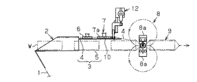
図1に概略的に示す横形製袋充填機においては、帯状フィルム1がフィルム供給源から上方に向けて製袋手段2に引き出し案内され、その製袋手段2において帯状フィルム1の長手方向(フィルム搬送方向である前後方向)へ延びる左右両端縁を上方に湾曲案内して立ち上げて合掌状に重合させた重合部4を有する筒状フィルム3が成形されると共に、この筒状フィルム3の胴部5内に物品Wが等間隔で順次供給され、該重合部4を一対の送りローラ6で挟持して筒状フィルム3が下流側へ搬送され、その下流位置に配設された縦シ−ル手段7における一対の両加熱シールローラ7aにより挟まれた重合部4に縦シ−ル部4a(図2(a)参照)が施された後に、筒状フィルム3中に所定間隔毎に供給された物品W間で横シ−ル手段8における一対の両加熱シールバー8aにより横シール部26(図2(a)参照)が施されることで、図2(a)に示すピロー包装袋による包装品9として排出される。
In the horizontal bag making and filling machine schematically shown in FIG. 1, the belt-like film 1 is drawn and guided to the bag making means 2 from the film supply source upward, and the longitudinal direction of the belt-like film 1 in the bag making means 2 (film A
その筒状フィルム3の搬送過程には、図3及び図4に示すように前記製袋手段2から前記縦シ−ル手段7の下流側へ所定寸法延在する案内板10が、上方に立ち上がる重合部4を挟む左右両側で水平に配設されている。この両案内板10の対向面間を重合部4が下流側に向けて通過可能なスリットからなる案内路11が形成され、前記胴部5の上部湾曲部5aが両案内板10の下側に面した状態で筒状フィルム3の重合部4がこの案内路11に沿って移動する。
In the process of transporting the
筒状フィルム3の搬送路より上方で前記縦シ−ル手段7の下流側に近接する位置における前記案内板10の上部位置に切込み形成手段12が配設されている。
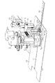
該切込み形成手段12においては、保持体14に配設された支柱15に取着されたガイドレール16に沿って垂直方向へ昇降動するスライダ17にホルダ18が取着された昇降機構13を備え、このホルダ18の下部にカッター19が着脱交換可能に配設されている。前記支柱15には、駆動手段としてのサーボモータ20が配設され、ホルダ18に連結されたクランク機構21に該サーボモータ20の回転が伝達されて昇降機構13が昇降作動される。カッター19の下端部に形成された刃部22は、尖端頂部22aから垂直に上方へ延びる前部切り刃22bを有していると共に、フィルム搬送方向上流側に向けて上方へ傾斜して延びる後部切り刃22cを有している。
A
The
該切込み形成手段12の下方において、前記両案内板10間の案内路11には、カッター19の下方への通過を許容するよう左右方向へ切り欠かれて広がる空所11aが設けられている。この空所11aの広がりは、カッター19を左右方向へ移動させた際に対応できるようにするためのものでもある。その空所11aの形成位置における前記両案内板10上にはフィルム搬送方向に間隔をあけて垂設された前後一対の支持棒23a,23bを有する左右一対の保持部材23が前記重合部4を挟む左右両側に相対向して取着されている。前記縦シ−ル手段7により縦シ−ルされた重合部4は、この保持部材23によって上方への立ち上げ姿勢が保持されると共に、その保持部材23の左右対向間隔は該重合部4の下流側への通過を許容するように設定されている。
Below the notch forming means 12, the
前記サーボモータ20の回転によりクランク機構21を介して昇降動するホルダ18に配設されたカッター19が垂直方向に昇降動するのに伴い、その下降時にこのカッター19の刃部22は空所11aを通過して案内板10の下方に至る。縦シ−ルされた重合部4は、筒状フィルム3の連続搬送に伴い、各保持部材23によってフィルム搬送方向の所定区間を上方へ立ち上がって張りを持つように挟まれて保持され、その重合部4に近接する一側方で案内板10の下方に面した筒状フィルム3の胴部5の上部湾曲部5aが刃部22により突き切られてその上部湾曲部5aに数ミリ程度の短尺の直線状となる切込み24(図4(b)参照)が形成される。カッター19の刃部22は傾斜する後部切り刃22cを有しているため、筒状フィルム3の連続搬送中においても、カッター19を垂直昇降動させるだけの動作で、筒状フィルム3の搬送が阻害されることなく、その後部切り刃22cにより上部湾曲部5aを確実かつ良好に突き切ることができる。
As the
前記カッター19の昇降動位置の下流側で案内板10の下流側端部から下流側に向けた前記横シール手段8による横シール位置の上流側近傍までに亘り折曲ガイド25が設けられ、案内路11で立ち上がって案内されていた縦シール部4aを有する重合部4がこの折曲ガイド25により胴部5側に向けて横倒しされる。このように重合部4が横倒しされた筒状フィルム3は、下流側に配設された横シール手段8において両加熱シールバー8a間に挟持されて横シール部26(図2(a)参照)が形成されるとともにその横シール部26間で筒状フィルム3が切断される。これにより、図2(a)に示すピロー包装袋による包装品9を得ることができる。
A bending
前記サーボモータ20は、入力手段により予め設定された制御データに基づきコントローラにより駆動制御され、カッター19の昇降動は、筒状フィルム3の搬送速度との関係で得られる包装品9の包装長に対応したフィルム搬送長さ毎の作動間隔で、且つ、前記ピロー包装袋の横シール部26の形成位置に一致して切込み形成可能なタイミングに設定される。なお、切込み24の形成位置は図2に示すようにピロー包装袋の横シール部26を有する袋の両終端部にまたがるように設定することが好ましい。このように開封始端となる切込み24を袋の両終端部に形成すれば、開封箇所の把握が容易でかつ袋開封方向に確実にフィルムを裂ける。また、切込み24の形成長さは、筒状フィルム3の搬送速度に対する前記サーボモータ20によるカッター19の下降時における筒状フィルム3との接触時間との関係についての動作タイミングを制御することで変更することができる。また、印刷フィルムが使用される際には、袋の印刷模様合わせとしてのレジマークをマークセンサ等によって検出した信号に基づき前記サーボモータ20の動作を制御し、切込みの長さや形成位置などを制御することが可能である。
The
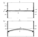
実施形態にかかる切込み形成装置によって得られるピロー包装袋において、図2(a)に示すように切込み24は、縦シ−ルされた重合部4が袋の胴部5に沿うように横倒しされて折り曲げられた側(一般的には商品の裏側とされる側)で該重合部4と袋の両端部に形成される横シール部26とが重なった交差部27から該重合部4の折り曲げ方向と反する向きへその折り曲げライン28から僅かに離れた近接位置で、両横シール部26が形成された袋の両端縁から相互の横シール部26間を結ぶ方向へ所定長さ(数ミリ)直線状に延びるように形成されている。袋の胴部5に沿って折り曲がった重合部4を図2(a)に示すように袋の胴部5から指などで摘んで持ち上げて両切込み24を基点に切込み24の延設方向に引っ張ると、図2(b)に示すように、フィルムが二枚重ねとなった重合部4に縦シ−ルが施されてフィルムの内面同士が溶着された部位から外れた袋の胴部5の一側面側の一枚のフィルム部分のみが縦シールラインに沿って引き裂き案内され、また、横シール部26で重なる上下のフィルムは横シール部26の溶着面同士を容易に剥離できるフィルム加工などの処理を施しておくことにより、横シール部26で重なった二枚重ねのフィルムをその溶着面を引き剥がすようにして袋を開封することができる。このようにして、袋の開封時には袋の上下二枚分のフィルムが袋の幅方向の一部を分断して引き裂かれることがないので、開封時に内容物を誤って破談してしまったり内容物がこぼれ落ちてしまったりすることがないなど、開封時の利便性を高めた包装形態とすることができる。また、ピロー包装袋による包装品9に形成される切込み24の形成位置は、両横シール部26のうちいずれか一方のみとするよう筒状フィルム3の搬送位置に対応して前記昇降機構13を作動制御してもよい。
In the pillow packaging bag obtained by the incision forming apparatus according to the embodiment, as shown in FIG. 2 (a), the
なお、兼用包装においても切込みを設けないピロー包装品9を得る場合においては、前記サーボモータ20による昇降機構13の動作を停止するだけの操作によって、対応することができる。
In addition, in the case of obtaining the
前記実施形態以外にも例えば下記のように構成してもよい。
・ カッター19は固定位置で昇降動するものに限らず、昇降動に加えて、例えばフィルム搬送速度に同調してフィルム搬送方向下流側に向けて水平移動する方式、その他の進退手段を含む機構を採用し得る。また、円盤状刃部をフィルム搬送速度より高速で回転させて下降しつつフィルム搬送方向に移動させる構成など、適宜の構成を採用可能である。このようにすることで、フィルム搬送速度が高速になった場合でも確実に切込み24を形成することができ、また、その切込み長さの精度を保つことができる。このようにすることで、カッター19の刃部22で傾斜した後部切り刃22cを省略することもできる。
For example, the following embodiment may be configured as follows.
The
・ カッター19の刃部22において切り刃の形状は、実施形態に限定されるものでなく、各種の形状とすることができる。必要に応じて、自由回転可能な円盤形状であってもよい。
-In the
・ カッター19を昇降動させる駆動源としてサーボモータ20を採用したが、他の駆動系からの機械式伝達手段を採用するようにしてもよい。
・ 切込み形成手段12は、縦シール手段7の下流側に配設したが、帯状フィルム1を筒状に成形してその左右両端縁を上方で合掌状に重合させた重合部4を左右両側から挟み込んで保持し得る位置であれば、例えば、製袋手段2から縦シール手段7に至るまでの間や、送りローラ6と加熱シールローラ7aとの間などのフィルム搬送経路に適宜位置に配設してもよい。
Although the
The
・ 実施形態では縦シ−ル部4aを有する重合部4の形成位置を袋幅の中央位置とし、また、切込み形成位置を該重合部4の折曲方向と反する側としたが、それらの各位置は、該重合部4を袋幅の中央から左右いずれか一側方へ寄った位置としたり、また切込み24を該重合部4の折曲方向と同一側の前記位置と同じ側に設けるようにしてもよい。複数品種に対する切込み位置に対応して切込み形成手段12の配設位置はフィルム搬送方向と直交する方向の適宜位置に設定すべく、保持体14をねじ調節機構その他の位置調節手段で位置調節可能に配設して切込み形成手段12を移動可能にすることが好ましい。
In the embodiment, the formation position of the
・ 縦シ−ルされた重合部4の保持は、フィルム搬送方向に間隔をあけて垂設した前後一対の支持棒23a,23bを有する左右一対の保持部材23によるものとしたが、これに代えて、所定範囲を支持可能な適宜部材、例えば、フィルム搬送方向の所定範囲に亘って延在する板状体やその他の保持部材であればよい。また、保持部材23は少なくともカッター19の昇降動による切込み形成に妨げとならないように、重合部4を袋の胴部5に向けて折り曲げて傾斜状に保持する構成としてもよい。
The holding of the vertically sealed overlapping
1…帯状フィルム、3…筒状フィルム、4…重合部、4a…縦シール部、7…縦シール手段、8…横シール手段、9…ピロー包装品、12…切込み形成手段、13…昇降機構、17…スライダ、19…カッター、20…サーボモータ(駆動手段)、21…クランク機構、22…刃部、22a…尖端頂部、22c…切り刃、23a,23b…保持部材、24…切込み、26…横シ−ル部。 DESCRIPTION OF SYMBOLS 1 ... Strip | belt-shaped film, 3 ... Cylindrical film, 4 ... Superposition | polymerization part, 4a ... Vertical seal part, 7 ... Vertical seal means, 8 ... Lateral seal means, 9 ... Pillow package article, 12 ... Incision formation means, 13 ... Lifting mechanism , 17 ... Slider, 19 ... Cutter, 20 ... Servo motor (drive means), 21 ... Crank mechanism, 22 ... Blade part, 22a ... Point top part, 22c ... Cutting blade, 23a, 23b ... Holding member, 24 ... Cutting, 26 ... Horizontal seal.
Claims (6)
Priority Applications (1)
| Application Number | Priority Date | Filing Date | Title |
|---|---|---|---|
| JP2008326333A JP5112279B2 (en) | 2008-12-22 | 2008-12-22 | Incision forming device for opening |
Applications Claiming Priority (1)
| Application Number | Priority Date | Filing Date | Title |
|---|---|---|---|
| JP2008326333A JP5112279B2 (en) | 2008-12-22 | 2008-12-22 | Incision forming device for opening |
Publications (2)
| Publication Number | Publication Date |
|---|---|
| JP2010143637A true JP2010143637A (en) | 2010-07-01 |
| JP5112279B2 JP5112279B2 (en) | 2013-01-09 |
Family
ID=42564477
Family Applications (1)
| Application Number | Title | Priority Date | Filing Date |
|---|---|---|---|
| JP2008326333A Active JP5112279B2 (en) | 2008-12-22 | 2008-12-22 | Incision forming device for opening |
Country Status (1)
| Country | Link |
|---|---|
| JP (1) | JP5112279B2 (en) |
Cited By (1)
| Publication number | Priority date | Publication date | Assignee | Title |
|---|---|---|---|---|
| JP2015053320A (en) * | 2013-09-05 | 2015-03-19 | 株式会社日立ハイテクインスツルメンツ | Component supply device, and component mounting apparatus using the same |
Families Citing this family (1)
| Publication number | Priority date | Publication date | Assignee | Title |
|---|---|---|---|---|
| CN108454920B (en) * | 2018-02-05 | 2019-12-03 | 钟玲 | A drug automatic packaging mechanism |
Citations (3)
| Publication number | Priority date | Publication date | Assignee | Title |
|---|---|---|---|---|
| JPS5579207A (en) * | 1978-12-09 | 1980-06-14 | Fuji Seal Ind Co Ltd | Unsealable snapped piece for thermally contracted film package* and method and rollers for making said piece |
| JPH10245017A (en) * | 1997-03-03 | 1998-09-14 | Kokusai Chiyaato Kk | Packaging method for heat-sensitive recording paper, and packaging bag for heat-sensitive recording paper using it |
| JP2011512301A (en) * | 2008-02-22 | 2011-04-21 | ベアンスタルク アンパーツゼルスカブ | Easy-to-open package |
-
2008
- 2008-12-22 JP JP2008326333A patent/JP5112279B2/en active Active
Patent Citations (3)
| Publication number | Priority date | Publication date | Assignee | Title |
|---|---|---|---|---|
| JPS5579207A (en) * | 1978-12-09 | 1980-06-14 | Fuji Seal Ind Co Ltd | Unsealable snapped piece for thermally contracted film package* and method and rollers for making said piece |
| JPH10245017A (en) * | 1997-03-03 | 1998-09-14 | Kokusai Chiyaato Kk | Packaging method for heat-sensitive recording paper, and packaging bag for heat-sensitive recording paper using it |
| JP2011512301A (en) * | 2008-02-22 | 2011-04-21 | ベアンスタルク アンパーツゼルスカブ | Easy-to-open package |
Cited By (1)
| Publication number | Priority date | Publication date | Assignee | Title |
|---|---|---|---|---|
| JP2015053320A (en) * | 2013-09-05 | 2015-03-19 | 株式会社日立ハイテクインスツルメンツ | Component supply device, and component mounting apparatus using the same |
Also Published As
| Publication number | Publication date |
|---|---|
| JP5112279B2 (en) | 2013-01-09 |
Similar Documents
| Publication | Publication Date | Title |
|---|---|---|
| CN103930349B (en) | Thermoforming packing machine | |
| US9505189B2 (en) | Apparatus for forming a plurality of flexible pouches from a continuous web of film | |
| JP6353592B1 (en) | Blister packing machine | |
| JP5112279B2 (en) | Incision forming device for opening | |
| JP6325935B2 (en) | Processing system | |
| JP4844989B2 (en) | Supply device for horizontal bag making and filling machine and control method thereof | |
| JP2020158190A (en) | Packaging machine | |
| JP4932424B2 (en) | Pillow packaging machine | |
| JPH06170989A (en) | Bag making machine | |
| EP2998108B1 (en) | Pouch maker for making block-bottom tobacco pouches | |
| CN108472911B (en) | Machine for manufacturing inflatable cushioning products | |
| JP2014193526A (en) | Peeling device for protective film of smc sheet | |
| JP6081735B2 (en) | Automatic packaging machine | |
| JP6286156B2 (en) | Top seal device | |
| JP5489518B2 (en) | Package supply device and packaging machine | |
| JP7851619B2 (en) | Sandwich packaging machine | |
| JP3437795B2 (en) | Packaging material processing equipment | |
| JP7667368B1 (en) | Machine and method for applying tubular shrink sleeve material to an object | |
| JP2004338752A (en) | Container sealing device | |
| JP4994784B2 (en) | Strip pack equipment | |
| JP2007112502A (en) | Strip bag equipment | |
| JP2005289498A (en) | Notch device in rotary automatic packaging machine | |
| JP3437792B2 (en) | Packaging sheet feeding device | |
| JPH0885523A (en) | Control device for pull tab unit | |
| JP2019026373A (en) | Bag making filling and packaging machine |
Legal Events
| Date | Code | Title | Description |
|---|---|---|---|
| A621 | Written request for application examination |
Free format text: JAPANESE INTERMEDIATE CODE: A621 Effective date: 20100715 |
|
| A977 | Report on retrieval |
Free format text: JAPANESE INTERMEDIATE CODE: A971007 Effective date: 20120229 |
|
| A131 | Notification of reasons for refusal |
Free format text: JAPANESE INTERMEDIATE CODE: A131 Effective date: 20120306 |
|
| A521 | Request for written amendment filed |
Free format text: JAPANESE INTERMEDIATE CODE: A523 Effective date: 20120507 |
|
| TRDD | Decision of grant or rejection written | ||
| A01 | Written decision to grant a patent or to grant a registration (utility model) |
Free format text: JAPANESE INTERMEDIATE CODE: A01 Effective date: 20121002 |
|
| A01 | Written decision to grant a patent or to grant a registration (utility model) |
Free format text: JAPANESE INTERMEDIATE CODE: A01 |
|
| A61 | First payment of annual fees (during grant procedure) |
Free format text: JAPANESE INTERMEDIATE CODE: A61 Effective date: 20121010 |
|
| FPAY | Renewal fee payment (event date is renewal date of database) |
Free format text: PAYMENT UNTIL: 20151019 Year of fee payment: 3 |
|
| R150 | Certificate of patent or registration of utility model |
Ref document number: 5112279 Country of ref document: JP Free format text: JAPANESE INTERMEDIATE CODE: R150 Free format text: JAPANESE INTERMEDIATE CODE: R150 |
|
| R250 | Receipt of annual fees |
Free format text: JAPANESE INTERMEDIATE CODE: R250 |
|
| R250 | Receipt of annual fees |
Free format text: JAPANESE INTERMEDIATE CODE: R250 |
|
| R250 | Receipt of annual fees |
Free format text: JAPANESE INTERMEDIATE CODE: R250 |
|
| R250 | Receipt of annual fees |
Free format text: JAPANESE INTERMEDIATE CODE: R250 |
|
| R250 | Receipt of annual fees |
Free format text: JAPANESE INTERMEDIATE CODE: R250 |
|
| R250 | Receipt of annual fees |
Free format text: JAPANESE INTERMEDIATE CODE: R250 |