JP2010143652A - Paper feeding device, paper feeding unit, and image forming device - Google Patents
Paper feeding device, paper feeding unit, and image forming device Download PDFInfo
- Publication number
- JP2010143652A JP2010143652A JP2008319555A JP2008319555A JP2010143652A JP 2010143652 A JP2010143652 A JP 2010143652A JP 2008319555 A JP2008319555 A JP 2008319555A JP 2008319555 A JP2008319555 A JP 2008319555A JP 2010143652 A JP2010143652 A JP 2010143652A
- Authority
- JP
- Japan
- Prior art keywords
- paper
- sheet
- suction
- detection sensor
- air outlet
- Prior art date
- Legal status (The legal status is an assumption and is not a legal conclusion. Google has not performed a legal analysis and makes no representation as to the accuracy of the status listed.)
- Granted
Links
Images
Classifications
-
- B—PERFORMING OPERATIONS; TRANSPORTING
- B65—CONVEYING; PACKING; STORING; HANDLING THIN OR FILAMENTARY MATERIAL
- B65H—HANDLING THIN OR FILAMENTARY MATERIAL, e.g. SHEETS, WEBS, CABLES
- B65H3/00—Separating articles from piles
- B65H3/08—Separating articles from piles using pneumatic force
- B65H3/12—Suction bands, belts, or tables moving relatively to the pile
- B65H3/124—Suction bands or belts
- B65H3/128—Suction bands or belts separating from the top of pile
-
- B—PERFORMING OPERATIONS; TRANSPORTING
- B65—CONVEYING; PACKING; STORING; HANDLING THIN OR FILAMENTARY MATERIAL
- B65H—HANDLING THIN OR FILAMENTARY MATERIAL, e.g. SHEETS, WEBS, CABLES
- B65H3/00—Separating articles from piles
- B65H3/46—Supplementary devices or measures to assist separation or prevent double feed
- B65H3/48—Air blast acting on edges of, or under, articles
-
- B—PERFORMING OPERATIONS; TRANSPORTING
- B65—CONVEYING; PACKING; STORING; HANDLING THIN OR FILAMENTARY MATERIAL
- B65H—HANDLING THIN OR FILAMENTARY MATERIAL, e.g. SHEETS, WEBS, CABLES
- B65H2511/00—Dimensions; Position; Numbers; Identification; Occurrences
- B65H2511/20—Location in space
-
- B—PERFORMING OPERATIONS; TRANSPORTING
- B65—CONVEYING; PACKING; STORING; HANDLING THIN OR FILAMENTARY MATERIAL
- B65H—HANDLING THIN OR FILAMENTARY MATERIAL, e.g. SHEETS, WEBS, CABLES
- B65H2511/00—Dimensions; Position; Numbers; Identification; Occurrences
- B65H2511/50—Occurence
- B65H2511/51—Presence
-
- B—PERFORMING OPERATIONS; TRANSPORTING
- B65—CONVEYING; PACKING; STORING; HANDLING THIN OR FILAMENTARY MATERIAL
- B65H—HANDLING THIN OR FILAMENTARY MATERIAL, e.g. SHEETS, WEBS, CABLES
- B65H2515/00—Physical entities not provided for in groups B65H2511/00 or B65H2513/00
- B65H2515/30—Forces; Stresses
- B65H2515/34—Pressure, e.g. fluid pressure
-
- B—PERFORMING OPERATIONS; TRANSPORTING
- B65—CONVEYING; PACKING; STORING; HANDLING THIN OR FILAMENTARY MATERIAL
- B65H—HANDLING THIN OR FILAMENTARY MATERIAL, e.g. SHEETS, WEBS, CABLES
- B65H2801/00—Application field
- B65H2801/03—Image reproduction devices
- B65H2801/06—Office-type machines, e.g. photocopiers
Landscapes
- Engineering & Computer Science (AREA)
- Mechanical Engineering (AREA)
- Sheets, Magazines, And Separation Thereof (AREA)
Abstract
【課題】紙種によらず用紙を吸着面に確実に吸着させると共に、吸着される用紙を1枚に分離することができる給紙装置を提供する。
【解決手段】給紙装置1Aは、吸着検知センサ6で検知される搬送ベルト30への用紙Pの吸着の有無、及び給紙検知センサ39で検知される用紙Pの搬送位置に基づいて、用紙載置台2に積載された用紙Pを浮上させる浮上動作タイミングと、搬送ベルト30に吸着された用紙Pを分離する分離動作タイミングを判断し、浮上動作タイミングでは浮上エア吹出口40を浮上位置に下降させ、分離動作タイミングでは浮上エア吹出口40を分離位置に上昇させる。
【選択図】 図1Provided is a paper feeding device capable of reliably adsorbing paper to an adsorption surface regardless of the type of paper and separating the adsorbed paper into one sheet.
A sheet feeding device (1A) is configured to use a sheet based on whether or not the sheet P is attracted to the transport belt (30) detected by the suction detection sensor (6) and the transport position of the sheet (P) detected by the sheet feed detection sensor (39). The floating operation timing for floating the paper P loaded on the mounting table 2 and the separation operation timing for separating the paper P adsorbed on the conveyor belt 30 are judged, and the floating air outlet 40 is lowered to the floating position at the floating operation timing. The floating air outlet 40 is raised to the separation position at the separation operation timing.
[Selection] Figure 1
Description
本発明は、積載された用紙の端縁に空気噴流を吹きつけて浮上させ、用紙を搬送ベルト等で構成される吸着面に吸着させて繰り出す給紙装置に関し、特に、吸着面に吸着される用紙の有無を検知した結果に基づいて、空気の吹出口の昇降制御を行うものである。 The present invention relates to a paper feeding device that blows an air jet to the edge of a stacked paper sheet and floats it, and sucks and feeds a paper sheet to a suction surface composed of a conveyor belt, and more particularly to a suction surface. Based on the result of detecting the presence or absence of paper, the air blow-up / down control of the air outlet is performed.
複写機等の画像形成装置の給紙装置として、従来からエア給紙装置が用いられている。エア給紙装置では、積載された用紙の側端面に空気噴流を吹きつけて浮上させ、浮上した用紙を、空気が吸引される吸気口が形成された穴開きベルト等の吸着面で吸着させ、ベルトを回転駆動して搬送する機構が用いられている。 Conventionally, an air feeding device has been used as a paper feeding device for an image forming apparatus such as a copying machine. In the air feeding device, an air jet is blown to the side end face of the loaded paper to float it, and the lifted paper is sucked by a suction surface such as a perforated belt in which an air inlet for sucking air is formed, A mechanism for rotating and transporting the belt is used.
エア給紙装置では、積載される用紙の上面位置より上側に空気の吹出口があると、薄紙では浮上させることができるものの、空気噴流が効率よく用紙の側面に当たらないため、厚紙が浮上しにくい。 With an air feeder, if there is an air outlet above the top surface of the loaded paper, thin paper can be lifted, but the air jet will not efficiently hit the side of the paper, so the thick paper will rise. Hateful.
一方、積載される用紙の上面位置より下側に空気の吹出口があると、厚紙でも浮上させることができる。但し、薄紙の場合は束で浮上しやすくなり、束で浮上した用紙の下側に空気噴流が通ることで、用紙を1枚に捌くことが困難になる。 On the other hand, if there is an air outlet on the lower side of the upper surface of the stacked paper, even thick paper can be lifted. However, in the case of thin paper, it becomes easy to float in a bundle, and it becomes difficult to spread the paper into one sheet because the air jet flows under the paper that has floated in the bundle.
そこで、空気の吹出口を昇降させる機構を備えると共に、空気の吹出口の昇降を、時間等の見込み制御で行う技術が提案されている(例えば、特許文献1参照)。 Therefore, a technique has been proposed in which a mechanism for raising and lowering the air outlet is provided and the air outlet is raised and lowered by speculative control such as time (see, for example, Patent Document 1).
しかし、従来のエア給紙装置では、見込み制御で空気の吹出口を昇降させるため、用紙が吸着面に吸着されない吸着不良が発生する可能性があった。また、複数枚の用紙を分離できず、重なった用紙が吸着面に吸着された状態で搬送される重送が発生する可能性があった。 However, in the conventional air sheet feeder, since the air outlet is moved up and down by the prospect control, there is a possibility that a suction failure occurs in which the paper is not sucked on the suction surface. In addition, a plurality of sheets cannot be separated, and there is a possibility that a double feed is performed in which the overlapped sheets are conveyed while being attracted to the suction surface.
本発明は、このような課題を解決するためになされたもので、紙種によらず用紙を吸着面に確実に吸着させると共に、吸着される用紙を1枚に分離することができる給紙装置、給紙装置を備えた給紙ユニット及び画像形成装置を提供することを目的とする。 The present invention has been made to solve such a problem, and is capable of reliably adsorbing a sheet to an adsorption surface regardless of the type of paper and separating the adsorbed sheet into one sheet. An object of the present invention is to provide a paper feeding unit and an image forming apparatus provided with a paper feeding device.
上述した課題を解決するため、請求項1に記載の発明は、複数枚の用紙が積載され、用紙の積載方向に沿って昇降する用紙載置台と、用紙載置台に積載された用紙を上面から吸引し、最上位の用紙を吸着面に吸着すると共に、吸着面に吸着された用紙を用紙搬送路に搬送する吸着搬送機構と、用紙載置台に積載された用紙が吸着面に向けて浮上する方向に沿って昇降する空気吹出口を有し、空気吹出口から用紙の側方に向けて空気を吹き出す送風機構と、空気吹出口を、用紙載置台に積載される用紙の側方に対向する第1の位置と吸着面に吸着された用紙の側方に対向する第2の位置に移動させる吹出口昇降機構と、吸着面に用紙が吸着されたか否かを検知する吸着検知センサと、吸着搬送機構で搬送される用紙を検知する給紙検知センサと、吸着検知センサで検知される吸着面への用紙の吸着の有無、及び給紙検知センサで検知される用紙の搬送位置に基づいて、用紙載置台に積載された用紙を浮上させる浮上動作タイミング、及び吸着搬送機構で吸着面に吸着された用紙を分離する分離動作タイミングを判断し、動作タイミングの判断結果に基づき吹出口昇降機構を制御して、浮上動作タイミングで空気吹出口を第1の位置に移動させ、分離動作タイミングで空気吹出口を第2の位置に移動させる制御部とを備えた給紙装置である。
In order to solve the above-described problem, the invention described in
請求項1に記載の給紙装置では、吸着検知センサ及び給紙検知センサの検知結果に基づいて、用紙載置台に積載された用紙を浮上させる浮上動作タイミングであるか、または吸着搬送機構で吸着面に吸着された用紙を分離する分離動作タイミングであるかが判断される。
In the sheet feeding device according to
浮上動作タイミングであれば、空気吹出口を第1の位置に移動させ、用紙載置台に積載された用紙の側方から空気を吹きつける。また、分離動作タイミングであれば、空気吹出口を第2の位置に移動させ、吸着面に吸着された用紙の側方から空気を吹きつける。 If it is the floating operation timing, the air outlet is moved to the first position, and air is blown from the side of the paper loaded on the paper placement table. At the separation operation timing, the air outlet is moved to the second position, and air is blown from the side of the sheet adsorbed on the adsorption surface.
これにより、吸着面に用紙が吸着されるまでは、用紙載置台に積載される用紙に側方から空気が吹き付けられ、用紙を確実に浮上させて吸着面に吸着させることができる。また、吸着面に用紙が吸着された後は、吸着面に吸着された用紙に側方から空気が吹き付けられ、複数枚の用紙が浮上したときに、用紙の間に空気を通して複数枚の用紙を捌き、吸着面に吸着された最上位の用紙以外を分離することができる。 As a result, until the sheet is adsorbed on the adsorption surface, air is blown from the side onto the sheet loaded on the sheet mounting table, and the sheet can be reliably lifted and adsorbed on the adsorption surface. Also, after the sheet is adsorbed on the adsorption surface, air is blown from the side to the sheet adsorbed on the adsorption surface, and when a plurality of sheets rise, the sheets are passed through the air. It is possible to separate the sheets other than the uppermost sheet adsorbed on the adsorption surface.
請求項2に記載の発明は、制御部は、吸着検知センサで吸着面に用紙が吸着されたことを検知しているとき、または、吸着検知センサで吸着面に用紙が吸着されたことを検知している間に、給紙検知センサで用紙が非検知となったときは、分離動作タイミングであると判断して、空気吹出口を第2の位置に移動させ、吸着検知センサで吸着面に用紙が未吸着であることを検知しているとき、または、吸着検知センサで吸着面に用紙が吸着されたことを検知している間に、給紙検知センサで用紙を検知したときは、浮上動作タイミングであると判断して、空気吹出口を第1の位置に移動させる請求項1に記載の給紙装置である。
In the invention according to
請求項2に記載の給紙装置では、連続給紙の際に吸着面に連続して用紙が吸着されると、吸着検知センサの出力が変化しない可能性があることを考慮して、吸着検知センサの出力から吸着面に用紙が吸着されていることを検知している間に、給紙検知センサの出力から搬送される用紙の有無を検知して、分離動作タイミングであるか浮上動作タイミングであるかが判断される。
In the sheet feeding device according to
請求項3に記載の発明は、空気吹出口の上部に、空気吹出口から吹き出される空気で浮上する用紙の側部に接する長さで突出する用紙押さえ部材を備えた請求項1または請求項2に記載の給紙装置である。 According to a third aspect of the present invention, there is provided a sheet pressing member that protrudes at a length in contact with a side portion of the sheet that is floated by the air blown out from the air outlet at the upper part of the air outlet. 2.
請求項3に記載の給紙装置では、空気吹出口から吹き出される空気で浮上させる用紙の側部が、用紙押さえ部材によって下向きに押さえられ、特に、紙厚の薄い用紙が束となって浮上することが抑制される。
In the sheet feeding device according to
請求項4に記載の発明は、用紙が収納される単数または複数の用紙トレイと、用紙トレイで複数枚の用紙が積載され、用紙の積載方向に沿って昇降する用紙載置台と、用紙載置台に積載された用紙を上面から吸引し、最上位の用紙を吸着面に吸着すると共に、吸着面に吸着された用紙を用紙搬送路に搬送する吸着搬送機構と、用紙載置台に積載された用紙が吸着面に向けて浮上する方向に沿って昇降する空気吹出口を有し、空気吹出口から用紙の側方に向けて空気を吹き出す送風機構と、空気吹出口を、用紙載置台に積載される用紙の側方に対向する第1の位置と吸着面に吸着された用紙の側方に対向する第2の位置に移動させる吹出口昇降機構と、吸着面に用紙が吸着されたか否かを検知する吸着検知センサと、吸着搬送機構で搬送される用紙を検知する給紙検知センサと、吸着検知センサで検知される吸着面への用紙の吸着の有無、及び給紙検知センサで検知される用紙の搬送位置に基づいて、用紙載置台に積載された用紙を浮上させる浮上動作タイミング、及び吸着搬送機構で吸着面に吸着された用紙を分離する分離動作タイミングを判断し、動作タイミングの判断結果に基づき吹出口昇降機構を制御して、浮上動作タイミングで空気吹出口を第1の位置に移動させ、分離動作タイミングで空気吹出口を第2の位置に移動させる制御部とを備えた給紙ユニットである。 According to a fourth aspect of the present invention, there is provided one or a plurality of paper trays in which paper is stored, a paper mounting table on which a plurality of papers are stacked in the paper tray, and moved up and down along the paper stacking direction, and a paper mounting table The sheet loaded on the sheet is sucked from the upper surface, the uppermost sheet is sucked to the suction surface, and the suction transport mechanism that transports the paper sucked on the suction surface to the paper transport path, and the paper stacked on the paper mounting table Has an air outlet that moves up and down along the direction of rising toward the suction surface, and a blower mechanism that blows air from the air outlet toward the side of the paper and an air outlet are stacked on the paper mounting table. A blow-out mechanism that moves to a first position that faces the side of the paper to be picked up and a second position that faces the side of the paper that is sucked by the suction surface; It is transported by the suction detection sensor to be detected and the suction transport mechanism. Based on the paper feed detection sensor that detects paper, the presence or absence of paper suction on the suction surface detected by the suction detection sensor, and the paper transport position detected by the paper feed detection sensor, The floating operation timing for floating the paper and the separation operation timing for separating the paper adsorbed on the suction surface by the suction conveyance mechanism are determined, and the blow-out mechanism is controlled based on the determination result of the operation timing, and the floating operation timing is determined. And a controller that moves the air outlet to the first position and moves the air outlet to the second position at the separation operation timing.
請求項4に記載の給紙ユニットでは、上述した給紙装置を備えることで、用紙を確実に浮上させて吸着面に吸着させることができると共に、吸着面に吸着された最上位の用紙以外を分離することができる。 In the paper feeding unit according to claim 4, by providing the above-described paper feeding device, the paper can be surely lifted and sucked on the suction surface, and other than the uppermost paper sucked on the suction surface. Can be separated.
請求項5に記載の発明は、用紙に画像を形成する画像形成部と、画像形成部に用紙を給紙する給紙装置と、給紙装置から画像形成部に用紙を給紙し、画像形成部で画像を形成する制御を行う制御部とを備え、給紙装置は、複数枚の用紙が積載され、用紙の積載方向に沿って昇降する用紙載置台と、用紙載置台に積載された用紙を上面から吸引し、最上位の用紙を吸着面に吸着すると共に、吸着面に吸着された用紙を用紙搬送路に搬送する吸着搬送機構と、用紙載置台に積載された用紙が吸着面に向けて浮上する方向に沿って昇降する空気吹出口を有し、空気吹出口から用紙の側方に向けて空気を吹き出す送風機構と、空気吹出口を、用紙載置台に積載される用紙の側方に対向する第1の位置と吸着面に吸着された用紙の側方に対向する第2の位置に移動させる吹出口昇降機構と、吸着面に用紙が吸着されたか否かを検知する吸着検知センサと、吸着搬送機構で搬送される用紙を検知する給紙検知センサとを備え、制御部は、吸着検知センサで検知される吸着面への用紙の吸着の有無、及び給紙検知センサで検知される用紙の搬送位置に基づいて、用紙載置台に積載された用紙を浮上させる浮上動作タイミング、及び吸着搬送機構で吸着面に吸着された用紙を分離する分離動作タイミングを判断し、動作タイミングの判断結果に基づき吹出口昇降機構を制御して、浮上動作タイミングで空気吹出口を第1の位置に移動させ、分離動作タイミングで空気吹出口を第2の位置に移動させる画像形成装置である。 According to a fifth aspect of the present invention, there is provided an image forming unit that forms an image on a sheet, a sheet feeding device that feeds the sheet to the image forming unit, and a sheet that is fed from the sheet feeding unit to the image forming unit. And a control unit that performs control to form an image in the unit. The sheet feeding device stacks a plurality of sheets and moves up and down along the sheet stacking direction, and the sheets stacked on the sheet stacking unit. From the upper surface, the uppermost paper is sucked to the suction surface, and the suction transport mechanism that transports the paper sucked on the suction surface to the paper transport path, and the paper loaded on the paper mounting table is directed to the suction surface A blower mechanism that blows air from the air outlet toward the side of the paper, and the air outlet is provided on the side of the paper loaded on the paper mounting table. A first position facing the second side and a second position facing the side of the sheet sucked by the suction surface A blower lift mechanism that moves to the device, a suction detection sensor that detects whether or not the paper is sucked on the suction surface, and a paper feed detection sensor that detects the paper transported by the suction transport mechanism. A floating operation timing for floating the paper loaded on the paper mounting table based on the presence or absence of the paper suction on the suction surface detected by the suction detection sensor and the paper transport position detected by the paper feed detection sensor; And a separation operation timing for separating the sheet adsorbed on the adsorption surface by the adsorption conveyance mechanism, and controlling the blowout lift mechanism based on the result of the determination of the operation timing, so that the air blowout outlet is positioned at the first position at the floating operation timing. And the air blower outlet is moved to the second position at the separation operation timing.
請求項5に記載の画像形成装置では、上述した給紙装置を備えることで、用紙を確実に浮上させて吸着面に吸着させることができると共に、吸着面に吸着された最上位の用紙以外を分離することができる。
In the image forming apparatus according to
本発明の給紙装置によれば、吸着面に用紙が吸着されるまでは、用紙載置台に積載される用紙に側方から空気を吹き付けて、用紙を確実に浮上させて吸着面に吸着させることができる。これにより、用紙が吸着面に吸着されない吸着不良を防止することができる。 According to the paper feeding device of the present invention, until the paper is sucked on the suction surface, air is blown from the side to the paper stacked on the paper mounting table, and the paper is surely lifted and sucked on the suction surface. be able to. As a result, it is possible to prevent a suction failure in which the paper is not attracted to the suction surface.
また、吸着面に用紙が吸着された後は、吸着面に吸着された用紙に側方から空気を吹き付けて、複数枚の用紙が浮上したときに、用紙の間に空気を通して複数枚の用紙を捌き、吸着面に吸着された最上位の用紙以外を分離することができる。これにより、複数枚の用紙が吸着面に吸着された状態で搬送される重送の発生を防止することができる。 In addition, after the sheet is adsorbed on the adsorption surface, air is blown from the side to the sheet adsorbed on the adsorption surface. It is possible to separate the sheets other than the uppermost sheet adsorbed on the adsorption surface. As a result, it is possible to prevent the occurrence of multiple feeding in which a plurality of sheets are conveyed while being attracted to the attracting surface.
本発明の給紙ユニットによれば、上述した給紙装置を備えることで、用紙が吸着面に吸着されない吸着不良を防止することができると共に、複数枚の用紙が吸着面に吸着された状態で搬送される重送の発生を防止することができる。また、本発明の画像形成装置によれば、上述した給紙装置を備えることで、用紙が吸着面に吸着されない吸着不良を防止することができると共に、複数枚の用紙が吸着面に吸着された状態で搬送される重送の発生を防止することができ、画像の品質を向上させることができる。 According to the paper feeding unit of the present invention, by providing the above-described paper feeding device, it is possible to prevent a suction failure in which the paper is not attracted to the suction surface, and in a state where a plurality of sheets are attracted to the suction surface. Occurrence of double feed to be conveyed can be prevented. In addition, according to the image forming apparatus of the present invention, by providing the above-described paper feeding device, it is possible to prevent a suction failure in which the paper is not attracted to the suction surface, and a plurality of sheets are attracted to the suction surface. It is possible to prevent the occurrence of double feeding that is conveyed in a state, and to improve the image quality.
以下、図面を参照して本発明の給紙装置、給紙装置を備えた給紙ユニット及び給紙ユニットが接続される画像形成装置の実施の形態について説明する。 Hereinafter, embodiments of a sheet feeding device, a sheet feeding unit including the sheet feeding device, and an image forming apparatus to which the sheet feeding unit is connected will be described with reference to the drawings.
<本実施の形態の給紙装置の構成例>
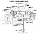
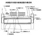
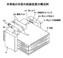
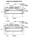
図1は、本実施の形態の給紙装置の一例を示す側面図、図2は、本実施の形態の給紙装置の一例を示す正面図、図3は、本実施の形態の給紙装置の一例を示す用紙収納部の斜視図である。
<Configuration Example of Paper Feeding Device of the Present Embodiment>
FIG. 1 is a side view illustrating an example of a sheet feeding device according to the present embodiment, FIG. 2 is a front view illustrating an example of a sheet feeding device according to the present embodiment, and FIG. 3 is a sheet feeding device according to the present embodiment. It is a perspective view of the paper storage part which shows an example.
本実施の形態の給紙装置1Aは、用紙載置台2に積載された用紙Pを吸着して繰り出す吸着搬送機構3と、用紙載置台2に積載された用紙Pに、側方から浮上エアA1を吹きつける浮上エア送風機構4を備える。また、給紙装置1Aは、吸着搬送機構3で吸着された用紙Pに、矢印Fで示す用紙Pの搬送方向に対する前方から分離エアA2を吹きつける分離エア送風機構5を備える。
The sheet feeding device 1A according to the present embodiment includes a
給紙装置1Aは、吸着搬送機構3で用紙Pが吸着されたか否か、及び、吸着搬送機構3で繰り出された用紙Pが搬送される位置に基づき判断される用紙載置台2に積載された用紙Pを浮上させるタイミングと、吸着搬送機構3で吸着された用紙Pを捌いて1枚に分離するタイミングに合わせて、浮上エアA1が吹き出される高さを切り替えられるように制御する。
The sheet feeding device 1A is loaded on the sheet loading table 2 that is determined based on whether or not the sheet P is sucked by the
以下に、本実施の形態の給紙装置1Aの詳細について説明する。給紙装置1Aは、所定枚数の用紙Pが積載された形態で収納可能な空間が形成される用紙収納部20に用紙載置台2を備える。
Details of the sheet feeding device 1A according to the present embodiment will be described below. The sheet feeding device 1A includes a sheet loading table 2 in a
用紙載置台2は、図示しない昇降機構によって用紙Pの積載方向に沿って昇降する。用紙収納部20は、用紙載置台2に積載される用紙Pの先端位置を規制する用紙先端突き当て面21が、用紙載置台2の昇降方向に沿って形成される。
The sheet placing table 2 is moved up and down along the stacking direction of the sheets P by a lifting mechanism (not shown). In the
給紙装置1Aは、用紙載置台2に積載された用紙Pの上面位置Puを検知する上限検知センサ22を備える。上限検知センサ22は、用紙Pの積載方向に沿って用紙先端突き当て面21の所定位置に検知位置が形成される例えば一対の光学センサで構成され、用紙載置台2に積載された用紙Pの上面位置Puが、吸着搬送機構3による吸着可能高さH1にあることを検知する位置に配置される。上限検知センサ22は、吸着可能高さH1に用紙Pが無い状態では、例えば出力がOFFになり、吸着可能高さH1に用紙Pが有る状態では出力がONになる。
The
給紙装置1Aは、用紙載置台2に積載された用紙Pが吸着搬送機構3で繰り出されることで、用紙載置台2上における用紙Pの積載高さが減少すると、用紙Pの上面位置Puが上限検知センサ22で検知される位置まで用紙載置台2を上昇させ、用紙載置台2に積載された用紙Pの上面位置Puが、吸着搬送機構3による吸着可能高さH1となるように制御される。
In the sheet feeding device 1A, when the stacking height of the sheet P on the sheet mounting table 2 is reduced by feeding the sheet P stacked on the sheet mounting table 2 by the
吸着搬送機構3は、用紙収納部20の上部に搬送ベルト30を備える。また、吸着搬送機構3は、搬送ベルト30が巻きつけられる駆動ローラ31と、第1の従動ローラ32と、2個の従動ローラを有した第2の従動ローラ群33を備える。
The
搬送ベルト30は無端状で、搬送ベルト30を貫通する吸気口30aが、搬送ベルト30の幅方向に並列され、搬送ベルト30の幅方向に並列される複数の吸気口30aが、搬送ベルト30の幅方向と直交する長さ方向の全体に形成される。
The
駆動ローラ31は、矢印Fで示す用紙Pの搬送方向に対して直交する方向に軸を有し、後述するモータにより回転駆動される。第1の従動ローラ32及び第2の従動ローラ群33は、駆動ローラ31の軸と平行な軸を有し、駆動ローラ31が回転駆動されることによる搬送ベルト30の回転に従動する回転自在な構成である。
The
吸着搬送機構3は、矢印Fで示す用紙Pの搬送方向に対して、用紙先端突き当て面21より前側に第2の従動ローラ群33が配置される。また、用紙載置台2の上部に駆動ローラ31が配置される。更に、第2の従動ローラ群33と駆動ローラ31の間で用紙載置台2の上部に第1の従動ローラ32が配置される。
In the
吸着搬送機構3は、駆動ローラ31と第2の従動ローラ群33との間で、搬送ベルト30が用紙Pの搬送方向に沿って張られる。これにより、吸着搬送機構3は、搬送ベルト30の駆動ローラ31に巻きつけられる後端側は、用紙載置台2に積載された用紙Pの上部に位置し、搬送ベルト30の第2の従動ローラ群33に巻きつけられる先端側は、用紙先端突き当て面21より前側に位置する。また、吸着搬送機構3は、2本の搬送ベルト30が、用紙Pの搬送方向に対して左右に並列する。
In the
そして、駆動ローラ31が矢印で示す方向に回転駆動されることで各搬送ベルト30が回転し、搬送ベルト30の用紙載置台2に面した側が、矢印Fで示す用紙Pの搬送方向に移動する。
Then, when the driving
駆動ローラ31の円周面における下端位置と、第1の従動ローラ32の円周面における下端位置は、略同一の高さとなるように構成される。これに対して、第2の従動ローラ群33のうち、下側の従動ローラの円周面における下端位置は、第1の従動ローラ32の下端位置より所定量高い位置となるように構成される。
The lower end position on the circumferential surface of the
これにより、搬送ベルト30の用紙載置台2に面した側で、駆動ローラ31と第1の従動ローラ32との間は、用紙載置台2に積載された用紙Pの面と略平行となる。これに対して、第1の従動ローラ32と第2の従動ローラ群33との間は、用紙Pの搬送方向に沿って上向きに傾斜しており、搬送ベルト30は、第1の従動ローラ32に巻きつけられた部位では屈曲した形態となる。
As a result, the side between the driving
吸着搬送機構3は、搬送ベルト30に用紙Pを吸着する空気が吸い込まれる吸着室34を備える。吸着室34は、図示しないファンにより空気が吸い込まれる空間が、搬送ベルト30の内側に形成され、用紙載置台2に面した側に位置する搬送ベルト30に対向する下側が開口し、用紙載置台2に面した側の搬送ベルト30の吸気口30aから空気が吸い込まれる。
The
吸着搬送機構3において、吸着室34の空気が図示しないファンにより吸い込まれると、吸着室34が負圧となることで、用紙載置台2に面した側に位置する搬送ベルト30の吸気口30aから空気が吸い込まれ、用紙載置台2に面した側の搬送ベルト30に用紙Pを吸着する空気の流れが発生する。
In the
これにより、吸気口30aから吸着室34に空気が吸い込まれる用紙載置台2に面した側の搬送ベルト30で、用紙Pを吸着する吸着面30bが構成される。
Accordingly, the
給紙装置1Aは、吸着搬送機構3で繰り出される用紙Pが搬送される用紙搬送路35を備える。用紙搬送路35は、吸着搬送機構3で吸着されて繰り出される用紙Pの搬送をガイドするガイド部材等を備え、用紙載置台2に面した側の搬送ベルト30と、用紙先端突き当て面21の上端との間に、用紙Pが進入する用紙進入口36が形成される。
The
給紙装置1Aは、用紙搬送路35に搬送ローラ37及び搬送ローラ37に対向する従動ローラ38を備える。搬送ローラ37は、後述するモータにより回転駆動され、吸着搬送機構3で繰り出された用紙Pを従動ローラ38との間に挟持して搬送する。
The
給紙装置1Aは、用紙搬送路35に給紙検知センサ39を備える。給紙検知センサ39は、搬送ローラ37及び従動ローラ38の上流側に検知位置が形成される例えば一対の光学センサで構成され、吸着搬送機構3で繰り出され、搬送ローラ37で搬送される用紙Pを検知する。給紙検知センサ39は、吸着搬送機構3で繰り出された用紙Pの先端が到達すると、例えば出力がONになり、搬送ローラ37で搬送されて用紙Pの後端が抜けると出力がOFFになる。
The
浮上エア送風機構4は送風機構の一例で、用紙収納部20の側方に空気吹出口として浮上エア吹出口40が形成される。浮上エア送風機構4では、送風ファン41で吸い込まれた空気が、浮上エア吹出口40から浮上エアA1として吹き出される。
The floating air blowing mechanism 4 is an example of a blowing mechanism, and a floating
給紙装置1Aは、送風ファン41による送風方向上部に吹出口形成ダクト42を備える。吹出口形成ダクト42は吹出口形成部材の一例で、図2に示すように、円弧状の曲面の内面で構成される風路形成部42aを有し、送風ファン41から上向きに吹き出される空気の流れを横向きに変える風路が形成される。
The
吹出口形成ダクト42は、風路形成部42aの下流側に、側方に向けて開口した浮上エア吹出口40が形成される。吹出口形成ダクト42は、図示しないガイド部材により、用紙Pの浮上方向に沿った上下方向に昇降可能に支持され、浮上エア吹出口40の高さが切り替えられる。
The blower
給紙装置1Aは、吹出口形成ダクト42を昇降させる吹出口昇降機構43を備える。吹出口昇降機構43は、吹出口形成ダクト42に連結されるリンク部材44と、リンク部材44を介して吹出口形成ダクト42を昇降させるソレノイド45と、リンク部材44を付勢するバネ46を備える。
The
リンク部材44は支点44aを軸に回転し、リンク部材44の回転動作が、吹出口形成ダクト42の昇降動作に変換される。ソレノイド45は、図示しないコイルに駆動電流を流すことで変位する可動子45aがリンク部材44に連結される。ソレノイド45が駆動されると、可動子45aが引き込まれ、バネ46を圧縮してリンク部材44が支点44aを軸に矢印C1方向に回転する。
The
リンク部材44が矢印C1方向に回転すると、リンク部材44に連結された吹出口形成ダクト42が下降する。これにより、ソレノイド45が駆動されると、浮上エア吹出口40が、図1及び図2に実線で示す第1の位置である浮上位置に移動する。
When the
浮上位置に移動した浮上エア吹出口40は、用紙載置台2に積載された用紙Pの側方に位置する。浮上エア送風機構4において、浮上エア吹出口40を浮上位置に移動させて浮上エアA1を吹き出すと、用紙載置台2に積載された用紙Pに側方から浮上エアA1が吹きつけられ、浮上エアA1で用紙Pを浮上させることができる。
The floating
一方、ソレノイド45が非駆動となると、可動子45aの吸引が解除され、バネ46の弾性力でリンク部材44が矢印C2方向に回転する。リンク部材44が矢印C2方向に回転すると、リンク部材44に連結された吹出口形成ダクト42が上昇する。これにより、ソレノイド45が非駆動となると、浮上エア吹出口40が、図1及び図2に二点鎖線で示す第2の位置である分離位置に移動する。
On the other hand, when the
分離位置に移動した浮上エア吹出口40は、吸着面30bを構成する搬送ベルト30に吸着された用紙Pの側方に位置する。浮上エア送風機構4において、浮上エア吹出口40を分離位置に移動させて浮上エアA1を吹き出すと、搬送ベルト30に吸着された用紙Pに側方から浮上エアA1が吹きつけられ、搬送ベルト30に2枚以上の用紙が吸着された場合にこれを捌いて、1枚に分離することができる。
The floating
浮上エア送風機構4は、浮上エア吹出口40に用紙押さえフラップ47を備える。用紙押さえフラップ47は用紙押さえ部材の一例で、浮上エア吹出口40から側方に突出する板状の部材が、浮上エア吹出口40の上端に取り付けられる。用紙押さえフラップ47は、用紙載置台2に積載された用紙Pを浮上エアA1で浮上させるときに、用紙Pの側部に接するように、浮上エア吹出口40から側方に所定の長さで突出する。用紙押さえフラップ47は、吹出口形成ダクト42の昇降と連動して上下動する。
The floating air blowing mechanism 4 includes a
分離エア送風機構5は、用紙進入口36から分離エアA2を吹き出す分離エア吹出口50を備える。分離エア送風機構5では、送風ファン51で吸い込まれた空気が、分離エア吹出口50から搬送ベルト30に対して用紙収納部20に向けて斜めに吹き出される。分離エア吹出口50から吹き出された分離エアA2は、用紙載置台2に面した側の搬送ベルト30に沿うような向きとなり、搬送ベルト30に吸着された用紙Pの前方から、用紙Pに対して略水平な向きで吹きつけられる。
The separation
給紙装置1Aは、吸着搬送機構3で搬送ベルト30に吸着される用紙Pの有無を検知する吸着検知センサ6を備える。吸着検知センサ6は、例えば一対の光学センサで構成され、吸着搬送機構3で搬送ベルト30に吸着される用紙Pに押し上げられて変位する検出子60の有無を検知する。すなわち、吸着搬送機構3で搬送ベルト30に用紙Pが吸着されると、搬送ベルト30で構成される吸着面30bから突出した検出子60を押し上げる力が加わる。検出子60を押し上げる力が加わると、バネ61が弾性変形して検出子60は軸62を支点に回転し、吸着面30bに対して格納される方向に変位する。
The
また、搬送ベルト30に吸着される用紙Pが無くなると、検出子60を押し上げる力が加わらなくなり、バネ61の弾性力で検出子60は軸62を支点に回転し、吸着面30bに対して突出する方向に変位する。
Further, when the sheet P attracted to the
このように、吸着搬送機構3による搬送ベルト30への用紙Pの吸着の有無で、検出子60は回転動作を行って変位する。吸着検知センサ6は、搬送ベルト30に用紙Pが吸着されていない状態では、例えば出力がOFFになり、搬送ベルト30に用紙Pが吸着された状態では出力がONになる。これにより、吸着検知センサ6の出力から、搬送ベルト30に用紙Pが吸着されたか否かが判断できる。
As described above, the detector 60 is displaced by the rotation operation depending on whether or not the sheet P is attracted to the
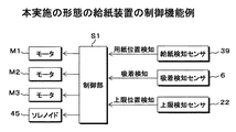
図4は、本実施の形態の給紙装置の制御系の一例を示す機能ブロック図である。給紙装置1Aは、各センサの出力等に基づいて、図1等で説明した用紙載置台2に積載された用紙Pを1枚ずつ繰り出す給紙制御を行う制御部S1を備える。なお、制御部S1は、後述する画像形成装置の制御部で構成しても良い。 FIG. 4 is a functional block diagram illustrating an example of a control system of the sheet feeding device according to the present embodiment. The sheet feeding device 1A includes a control unit S1 that performs sheet feeding control for feeding the sheets P stacked on the sheet placing table 2 described with reference to FIG. Note that the control unit S1 may be configured by a control unit of an image forming apparatus described later.
制御部S1は、図1等に示す吸着搬送機構3で搬送ベルト30に用紙Pが吸着されたことを、吸着検知センサ6の出力から検知する。また、制御部S1は、吸着搬送機構3で繰り出された用紙Pの先端及び後端が所定の位置に到達したことを、給紙検知センサ39の出力から検知する。
The controller S1 detects from the output of the
制御部S1は、吸着検知センサ6で検知される搬送ベルト30への用紙Pの吸着の有無と、給紙検知センサ39で検知される用紙Pの搬送位置に基づいて、浮上エア吹出口40の高さが切り替えられる。浮上エア吹出口40の高さは、ソレノイド45の駆動と非駆動を制御することで吹出口形成ダクト42を昇降させて、浮上位置と分離位置に切り替えられる。
The control unit S1 determines whether or not the floating
また、制御部S1は、吸着検知センサ6で検知される搬送ベルト30への用紙Pの吸着の有無と、給紙検知センサ39で検知される用紙Pの搬送位置に基づいて、搬送ベルト30を駆動するモータM1と、搬送ローラ37を駆動するモータM2を制御する。
Further, the control unit S1 controls the
制御部S1は、上限検知センサ22で検知される用紙Pの上面位置に基づいて、用紙載置台2を昇降させるモータM3を制御し、用紙載置台2に積載された用紙Pの上面位置Puを、給紙可能高さH1に合わせる。
Based on the upper surface position of the paper P detected by the upper
<本実施の形態の給紙装置の動作例>
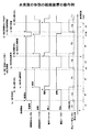
図5は、本実施の形態の給紙装置の動作例を示す正面図、図6は、本実施の形態の給紙装置の動作の一例を示すタイムチャートで、次に、各図を参照して、本実施の形態の給紙装置1Aの動作例について説明する。
<Operation Example of Paper Feeding Device of the Present Embodiment>
FIG. 5 is a front view showing an example of the operation of the paper feeding device of the present embodiment, and FIG. 6 is a time chart showing an example of the operation of the paper feeding device of the present embodiment. An example of the operation of the sheet feeding device 1A according to this embodiment will be described.
制御部S1は、給紙動作を開始すると、上限検知センサ22の出力に基づいて、用紙載置台2に積載された用紙Pの上面位置Puが、吸着搬送機構3による吸着可能高さH1となるように、用紙載置台2を昇降させるモータM3を制御する。
When the control unit S1 starts the paper feeding operation, the upper surface position Pu of the paper P stacked on the paper placement table 2 becomes the suctionable height H1 by the
用紙Pの給紙動作では、吸着搬送機構3の図示しないファンが駆動されると共に、浮上エア送風機構4の送風ファン41と、分離エア送風機構5の送風ファン51が駆動され、まず、用紙Pの浮上及び吸着動作が行われる。
In the paper feeding operation of the paper P, a fan (not shown) of the
用紙Pの浮上及び吸着動作では、吸着検知センサ6の出力から搬送ベルト30に用紙Pが未吸着であると判断すると、制御部S1は、ソレノイド45を駆動して、浮上エア吹出口40を、図5(a)に示すように浮上位置に下降させる。
In the floating and suction operations of the paper P, when it is determined from the output of the
吸着室34の空気が図示しないファンにより吸い込まれると、吸着室34が負圧となることで、用紙載置台2に面した側に位置する搬送ベルト30の吸気口30aから空気が吸い込まれ、用紙載置台2に面した側の搬送ベルト30に用紙Pを吸着する空気の流れが発生する。
When the air in the suction chamber 34 is sucked in by a fan (not shown), the suction chamber 34 becomes negative pressure, so that air is sucked in from the air inlet 30a of the
また、浮上エア送風機構4において、浮上エア吹出口40を浮上位置に下降させた状態で、送風ファン41が駆動されて浮上エア吹出口40から浮上エアA1が吹き出されると、用紙載置台2に積載された用紙Pの側方から浮上エアA1が吹きつけられる。
In the floating air blowing mechanism 4, when the blower fan 41 is driven and the floating air A <b> 1 is blown out from the floating
これにより、用紙載置台2に積載された用紙Pにおいて、上側に積載される用紙Pが浮上を開始する。図6に示す時間t1は、給紙動作を開始してから、浮上した用紙Pが搬送ベルト30に吸着されるのを待つ時間であり、吸着検知センサ6の出力から判断される浮上動作タイミングTUである。
As a result, the paper P stacked on the upper side of the paper P stacked on the paper mounting table 2 starts to float. A time t1 shown in FIG. 6 is a time for waiting for the floated paper P to be attracted to the
用紙載置台2に積載された最上位の用紙Pは、図6に示すタイミングtaで、吸着面30bを構成する搬送ベルト30に吸着される。用紙Pが搬送ベルト30に吸着されると、吸着検知センサ6を構成する検出子60が、用紙Pを吸着する力で押し上げられる。検出子60は、バネ61が弾性変形して軸62を支点に回転する。
The uppermost sheet P stacked on the sheet placing table 2 is adsorbed by the
これにより、図6に示すタイミングtaで、検出子60が吸着検知センサ6で検知され、吸着検知センサ6の出力がON(吸着有)に変化すると、制御部S1は、搬送ベルト30に用紙P、ここでは1枚目の用紙Pが吸着されたと判断する。
Thereby, at the timing ta shown in FIG. 6, when the detector 60 is detected by the
制御部S1は、搬送ベルト30に用紙Pが吸着されたことを検知すると、吸着検知センサ6の出力から分離動作タイミングTSになったと判断し、ソレノイド45の駆動を停止して、浮上エア吹出口40を、図5(b)に示すように分離位置に上昇させ、用紙Pの分離及び搬送動作に移行する。
When the control unit S1 detects that the paper P is adsorbed to the
浮上エア吹出口40は、搬送ベルト30に用紙Pが吸着されたことを、吸着検知センサ6の出力に基づき検知するまでは、浮上位置で保持される。用紙載置台2に紙厚の厚い厚紙がセットされている場合でも、用紙載置台2に積載された用紙Pの側面に効率良く浮上エアA1が当たり、用紙Pを確実に浮上させることができる。これにより、用紙載置台2に積載される用紙Pの紙種によらず、未吸着ジャムが発生するということを防ぐことができる。
The floating
また、搬送ベルト30に用紙Pが吸着されるまで、浮上エア吹出口40が浮上位置で保持されることで、浮上エアA1で浮上させる用紙Pの側部が、用紙押さえフラップ47で下向きに押さえられる。用紙載置台2に紙厚の薄い薄紙がセットされている場合、用紙Pの側方から浮上エアA1が吹きつけられると、複数枚の用紙Pが束になった形態で上昇しやすい。このとき、浮上エアA1で浮上させる用紙Pの側部を、用紙押さえフラップ47で下向きに押さえることで、搬送ベルト30に吸着される最上位の1枚の用紙P1以外の2枚目以降の用紙P2の浮上が抑えられ、複数枚の用紙Pが搬送ベルト30に吸着することを抑制できる。
Further, the floating
用紙載置台2に面した側に位置する搬送ベルト30は、第1の従動ローラ32に巻きつけられた部位では屈曲した形態で、第1の従動ローラ32と第2の従動ローラ群33との間に位置する搬送ベルト30が、用紙Pの搬送方向に沿って上向きに傾斜している。これにより、搬送ベルト30に吸着された用紙Pは、搬送ベルト30が第1の従動ローラ32に巻きつけられた部位で屈曲した形態となる。
The
搬送ベルト30に2枚以上の用紙Pが吸着された場合、静電気力等で複数枚の用紙Pが貼り付いた状態となっている。搬送ベルト30に吸着される最上位の1枚の用紙は、吸着エアによる吸着力が直接働くので、搬送ベルト30が第1の従動ローラ32に巻きつけられた部位に倣って屈曲した形態で、搬送ベルト30に吸着された形態となる。
When two or more sheets P are attracted to the
これに対して、最上位の用紙に貼り付いて搬送ベルト30に吸着される2枚目以降の用紙は、吸着エアによる吸着力が直接働かない。これにより、2枚目以降の用紙は、第1の従動ローラ32に巻きつけられた部位の搬送ベルト30の屈曲した形態に倣わず、最上位の1枚の用紙と2枚目以降の用紙が先端面から分離される。
On the other hand, the second and subsequent sheets that are attached to the uppermost sheet and are adsorbed by the
分離エア送風機構5において送風ファン51が駆動され、分離エア吹出口50から吹き出された分離エアA2は、用紙載置台2に面した側の搬送ベルト30に沿うような向きとなり、搬送ベルト30に吸着された用紙Pの前方から、用紙Pに対して略水平な向きで吹きつけられる。
In the separation
また、浮上エア送風機構4では、浮上エアA1の吹き出しが継続され、浮上エア吹出口40を分離位置に上昇させて浮上エアA1が吹き出されると、搬送ベルト30に吸着された用紙Pに側方から浮上エアA1が吹きつけられる。
Further, in the floating air blowing mechanism 4, when the floating air A <b> 1 continues to be blown out and the floating
吸着搬送機構3で2枚以上の用紙Pが吸着された場合、搬送ベルト30に吸着された用紙Pの前方から吹きつけられる分離エアA2と、分離位置に上昇させた浮上エア吹出口40から吹き出され、搬送ベルト30に吸着された用紙Pの側方から吹きつけられる浮上エアA1により、最上位の1枚の用紙P1と2枚目以降の用紙P2が分離される。
When two or more sheets P are adsorbed by the
用紙載置台2に紙厚の薄い薄紙がセットされており、浮上及び吸着動作において薄紙が束で浮上した場合でも、分離位置にある浮上エア吹出口40から浮上エアA1が吹き出されることで、搬送ベルト30に吸着された最上位の1枚の用紙P1と、2枚目以降の用紙P2の間に浮上エアA1を通すことができる。
Even if thin paper is set on the paper mounting table 2 and the thin paper floats in a bundle in the floating and suction operations, the floating air A1 is blown out from the floating
これにより、束で浮上した用紙Pを浮上エアA1で捌いて、搬送ベルト30に吸着された最上位の1枚の用紙以外を分離させることができ、用紙載置台2に積載される用紙Pの紙種によらず、搬送時における重送ジャムの発生を防ぐことができる。
As a result, the sheets P that have floated in the bundle can be spun with the flying air A1 to separate the sheets other than the topmost sheet adsorbed by the
また、浮上エア吹出口40は、搬送ベルト30に用紙Pが吸着されたことを、吸着検知センサ6の出力に基づき検知してから分離位置に上昇させるので、搬送ベルト30に用紙Pが吸着される前に分離位置に移動することはない。これにより、搬送ベルト30に用紙Pが吸着される前に、用紙載置台2に積載された用紙Pの側面に効率良く浮上エアA1が当たらなくなり、用紙Pが浮上せずに未吸着ジャムが発生するということを防ぐことができる。
Further, the floating
更に、搬送ベルト30に用紙Pが吸着されると、浮上エア吹出口40を分離位置に上昇させるので、用紙Pの分離及び搬送動作では、用紙押さえフラップ47を退避させることができる。用紙載置台2に紙厚の厚い厚紙がセットされている場合、搬送ベルト30に吸着された用紙Pの側部が、用紙押さえフラップ47で下向きに押さえられていると、用紙Pが搬送ベルト30から離れてしまう場合がある。また、後述する用紙Pの搬送時に余計な負荷が掛かる。このため、用紙Pの分離及び搬送動作では、用紙押さえフラップ47を退避させる。そして、用紙押さえフラップ47を浮上エア吹出口40に備えることで、用紙押さえフラップ47の昇降を、浮上エア吹出口40の昇降と連動させることができ、用紙押さえフラップ47を昇降させるための独立した駆動機構が不用で、構成及び制御の単純化を図ることができる。
Further, when the paper P is attracted to the
本実施の形態の給紙装置1Aでは、搬送ベルト30に用紙Pが吸着する前は浮上エア吹出口40を浮上位置に下降させ、搬送ベルト30に用紙Pが吸着した後は浮上エア吹出口40を分離位置に上昇させることで、浮上エアA1の風量が一定であっても、用紙Pの浮上と分離の機能を両立させることができる。但し、浮上エア送風機構4で吹き出される浮上エアA1の風量の強弱を、図示しないシャッタの開閉等で切り換えられる構成にして、吸着検知センサ6で用紙Pの吸着を検知するまでは、強風量で浮上エアA1を吹き出し、吸着検知センサ6で用紙Pの吸着を検知すると、弱風量に切り換えて浮上エアA1を吹き出すようにしても良い。
In the sheet feeding device 1A of the present embodiment, the floating
図6に示す時間t2は、タイミングtaで吸着検知センサ6の出力がONに変化して、搬送ベルト30に用紙Pが吸着されたことを検知してから、上述したように、分離エアA2と浮上エアA1等の作用で用紙Pを分離させるための分離待機時間である。
At time t2 shown in FIG. 6, the output of the
制御部S1は、タイミングtaで吸着検知センサ6の出力がONに変化して、搬送ベルト30に用紙Pが吸着されたことを検知すると、所定の分離待機時間t2が経過したタイミングtbで、モータM1により吸着搬送機構3の駆動ローラ31を回転駆動すると共に、モータM2により搬送ローラ37を回転駆動して、用紙Pの搬送動作を開始する。
When the output of the
駆動ローラ31が矢印で示す方向に回転駆動されると、搬送ベルト30が回転し、搬送ベルト30の用紙載置台2に面した側が、矢印Fで示す方向に移動する。これにより、吸着搬送機構3で搬送ベルト30に吸着された用紙Pは、矢印Fで示す搬送方向に繰り出される。なお、用紙Pの搬送動作では、分離エア送風機構5による分離エアA2の吹き出しが継続しているので、分離された2枚目以降の用紙Pを用紙収納部20方向に戻す力が生じている。これにより、1枚目の用紙Pにつられて2枚目の用紙Pが用紙進入口36へ搬送されることが防止される。
When the driving
吸着搬送機構3で吸着された用紙Pが搬送ベルト30により繰り出されると、繰り出される用紙Pの先端が、タイミングtcで給紙検知センサ39の検知位置に進入して、給紙検知センサ39の出力がON(紙有)に変化し、用紙Pが検知される。また、用紙Pの先端が給紙検知センサ39に到達した後、搬送ベルト30による繰り出しを継続して所定時間が経過すると、用紙Pの先端が搬送ローラ37と従動ローラ38で挟持される。
When the paper P sucked by the
制御部S1は、タイミングtcで給紙検知センサ39の出力がONに変化して、搬送ベルト30により繰り出された用紙Pの先端が給紙検知センサ39に到達したこと検知した後、搬送ローラ37と従動ローラ38で用紙Pを挟持するまでの時間を考慮して設定された所定の待機時間が経過すると、搬送ベルト30の回転駆動を停止する。一方、搬送ローラ37の回転駆動は継続する。
The control unit S1 detects that the output of the paper
また、制御部S1は、タイミングtcで給紙検知センサ39の出力がONに変化して、搬送ベルト30の回転駆動を停止すると、給紙検知センサ39の出力から浮上動作タイミングTUになったと判断し、次の用紙Pの浮上及び吸着動作のために、ソレノイド45を駆動して、浮上エア吹出口40を浮上位置に下降させる。
Further, when the output of the paper
これにより、時間t3で、搬送ローラ37と従動ローラ38に挟持された用紙Pが搬送される。なお、用紙Pの搬送動作では、吸着搬送機構3による用紙Pの吸着動作が継続しており、搬送ベルト30に用紙Pを吸着する力が働いているが、搬送ローラ37と従動ローラ38の挟持による搬送力の方が吸着力より強く、搬送ベルト30を停止させた状態で用紙Pが引き抜かれる。
As a result, the sheet P sandwiched between the
搬送ローラ37と従動ローラ38に挟持された用紙Pが搬送されると、用紙Pの後端が吸着検知センサ6を抜ける。用紙Pの後端が吸着検知センサ6を抜けると、連続して用紙Pが吸着されなければ、吸着検知センサ6を構成する検出子60の変位で吸着検知センサ6の出力がOFF(吸着無)に変化する。
When the paper P sandwiched between the
また、搬送ローラ37と従動ローラ38に挟持された用紙Pが搬送されると、用紙Pの後端が給紙検知センサ39を抜ける。用紙Pの後端が給紙検知センサ39を抜けると、給紙検知センサ39の出力がOFF(紙無)に変化する。
When the paper P sandwiched between the
制御部S1は、給紙検知センサ39の出力がOFFに変化すると、搬送ローラ37の回転駆動を停止する制御を行う。また、給紙検知センサ39の出力がOFFになったタイミングにおける吸着検知センサ6の出力に基づき、浮上エア吹出口40を分離位置に上昇させる分離動作タイミングTSになったか否かを判断する。
When the output of the paper
すなわち、用紙Pの搬送動作では、吸着搬送機構3による用紙Pの吸着動作が継続しており、また、先行する用紙Pの先端が給紙検知センサ39に到達すると、浮上エア吹出口40を浮上位置に下降させるので、先行する1枚目の用紙Pが搬送される途中で露出する搬送ベルト30に、2枚目の用紙Pが吸着されることがある。但し、上述したように、1枚目の用紙Pの先端が給紙検知センサ39で検知されると、所定のタイミングで搬送ベルト30の駆動が停止されるので、1枚目の用紙Pの搬送途中で搬送ベルト30に吸着された2枚目の用紙Pは搬送されない。
That is, in the transport operation of the paper P, the suction operation of the paper P by the
これにより、1枚目の用紙Pの後端が吸着検知センサ6を抜けたタイミングtdの段階で、2枚目の用紙Pが搬送ベルト30に吸着されており、タイミングteで1枚目の用紙Pの後端が給紙検知センサ39を抜けて給紙検知センサ39の出力がOFFになるまでの時間t4の間に、吸着検知センサ6の出力がON(吸着有)のまま変化しない場合がある。
As a result, at the timing td when the trailing edge of the first sheet P passes through the
このように、先行する用紙Pの搬送に伴い後続する用紙Pが続けて搬送ベルト30に吸着されることで、吸着検知センサ6の出力が変化しない状態を考慮して、制御部S1は、吸着検知センサ6と給紙検知センサ39の出力を利用して、浮上エア吹出口40の昇降制御及び搬送ベルト30等による搬送制御を行う。
In this way, in consideration of the state where the output of the
制御部S1は、搬送ローラ37と従動ローラ38に挟持されて搬送される用紙Pの後端が給紙検知センサ39を抜けることで、給紙検知センサ39の出力がOFFに変化したとき、吸着検知センサ6の出力がON、すなわち、次の用紙Pが既に搬送ベルト30に吸着されている状態では、分離動作タイミングTSになったと判断し、ソレノイド45の駆動を停止して、浮上エア吹出口40を分離位置に上昇させる。
When the output of the paper
用紙Pを連続給紙する場合は、先行する用紙Pの後端が給紙検知センサ39を抜けると、次の用紙の給紙の準備に移行するが、次の用紙Pが既に搬送ベルト30に吸着されている状態では、更に用紙を浮上させる必要が無い。そこで、先行する用紙Pの後端が給紙検知センサ39を抜けると、次の用紙が搬送ベルト30に既に吸着されていれば、直ちに浮上エア吹出口40を分離位置に上昇させる。
In the case of continuously feeding the paper P, when the trailing edge of the preceding paper P passes through the paper
これに対して、制御部S1は、給紙検知センサ39の出力がOFFに変化したとき、吸着検知センサ6の出力がOFF、すなわち、次の用紙Pが搬送ベルト30に未吸着の状態では、浮上動作タイミングTUであると判断し、次の用紙Pが搬送ベルト30に吸着されて、吸着検知センサ6の出力がONになるまで、浮上エア吹出口40を浮上位置に保持する。
In contrast, when the output of the paper
また、給紙検知センサ39の出力がOFFに変化したとき、吸着検知センサ6の出力がONであると、給紙検知センサ39の出力がOFFに変化した後で、所定の分離待機時間経過後に、搬送ベルト30と搬送ローラ37の回転駆動を開始する。
Further, when the output of the paper
これに対して、給紙検知センサ39の出力がOFFに変化したとき、吸着検知センサ6の出力がOFFであると、吸着検知センサ6の出力がONに変化した後で、所定の分離待機時間経過後に、搬送ベルト30と搬送ローラ37の回転駆動を開始する。
On the other hand, when the output of the paper
図6に示す例では、搬送ローラ37と従動ローラ38に挟持された1枚目の用紙Pが搬送され、タイミングteで1枚目の用紙Pの後端が給紙検知センサ39を抜ける。1枚目の用紙Pの後端が給紙検知センサ39を抜けて給紙検知センサ39の出力がOFFに変化すると、2枚目の用紙Pの給紙の準備に移行する。制御部S1は、給紙検知センサ39の出力がOFFに変化すると、搬送ローラ37の回転駆動を停止する制御を行う。また、吸着検知センサ6の出力がONであるので、ソレノイド45の駆動を停止して、浮上エア吹出口40を分離位置に上昇させる。
In the example shown in FIG. 6, the first sheet P sandwiched between the
タイミングteでは、2枚目の用紙Pが搬送ベルト30に既に吸着されているので、時間t5は、タイミングteで給紙検知センサ39の出力がOFFに変化してから、分離エアA2と浮上エアA1等の作用で用紙Pを分離させるための分離待機時間である。
At timing te, since the second sheet P is already attracted to the
制御部S1は、1枚目の用紙Pが給紙検知センサ39を抜けてから、所定の分離待機時間t5が経過したタイミングtfで、搬送ベルト30と搬送ローラ37を回転駆動して、2枚目の用紙Pの繰り出しを開始する。
The control unit S1 rotates the
搬送ベルト30に吸着された2枚目の用紙Pが繰り出されると、タイミングtgで給紙検知センサ39の出力がONに変化し、2枚目の用紙Pの先端が給紙検知センサ39に到達したことが検知される。
When the second sheet P attracted to the
制御部S1は、タイミングtgで給紙検知センサ39の出力がONに変化して、搬送ベルト30により繰り出された用紙Pの先端が給紙検知センサ39に到達したこと検知した後、搬送ローラ37と従動ローラ38で用紙Pを挟持するまでの時間を考慮して設定された所定の待機時間が経過すると、搬送ベルト30の回転駆動を停止する。一方、搬送ローラ37の回転駆動は継続する。これにより、時間t6で、搬送ローラ37と従動ローラ38に挟持された用紙Pが搬送される。
The control unit S1 detects that the output of the paper
また、制御部S1は、搬送ベルト30の回転駆動を停止すると、次の用紙Pの浮上動作のために、ソレノイド45を駆動して、浮上エア吹出口40を浮上位置に下降させる。
Further, when the rotation of the conveying
搬送ローラ37と従動ローラ38に挟持された用紙Pが搬送されると、タイミングthで2枚目の用紙Pの後端が吸着検知センサ6を抜ける。用紙Pの後端が吸着検知センサ6を抜けると、3枚目の用紙Pが続けて搬送ベルト30に吸着されていなければ、吸着検知センサ6を構成する検出子60の変位で吸着検知センサ6の出力がOFF(吸着無)に変化する。このとき、2枚目の用紙Pの後端は、給紙検知センサ39に到達しておらず、給紙検知センサ39の出力はONである。
When the paper P sandwiched between the
搬送ローラ37と従動ローラ38に挟持された2枚目の用紙Pが更に搬送されると、タイミングtiで2枚目の用紙Pの後端が給紙検知センサ39を抜ける。用紙Pの後端が給紙検知センサ39を抜けると、給紙検知センサ39の出力がOFFに変化する。
When the second sheet P sandwiched between the
制御部S1は、2枚目の用紙Pが給紙検知センサ39を抜けて、給紙検知センサ39の出力がOFFに変化すると、3枚目の用紙Pの給紙の準備に移行する。
When the second paper P passes through the paper
制御部S1は、給紙検知センサ39の出力がOFFに変化すると、搬送ローラ37の回転駆動を停止する制御を行う。また、制御部S1は、給紙検知センサ39の出力がOFFに変化したとき、吸着検知センサ6の出力がOFF、すなわち、次の用紙Pが搬送ベルト30に未吸着の状態では、次の用紙Pが搬送ベルト30に吸着されて、吸着検知センサ6の出力がONになるまで、浮上エア吹出口40を浮上位置に保持する。
When the output of the paper
2枚目の用紙Pが吸着検知センサ6を抜けると、吸着搬送機構3による吸着動作は継続していると共に、浮上位置に下降させた浮上エア吹出口40から浮上エアA1が吹き出されているので、3枚目の用紙Pが搬送ベルト30に吸着される。時間t7,t8は、2枚目の用紙Pが吸着検知センサ6を抜けてから、3枚目の用紙Pが搬送ベルト30に吸着されるのを待つ浮上・吸着待機時間である。
When the second sheet P passes through the
3枚目の用紙Pが、タイミングtjで搬送ベルト30に吸着されると、検出子60が吸着検知センサ6で検知されることで、吸着検知センサ6の出力がON(吸着有)に変化し、制御部S1は、搬送ベルト30に用紙Pが吸着されたと判断する。
When the third sheet P is attracted to the
制御部S1は、給紙検知センサ39の出力がOFFで、吸着検知センサ6の出力がONに変化すると、ソレノイド45の駆動を停止して、浮上エア吹出口40を分離位置に上昇させ、3枚目の用紙Pの分離及び搬送動作に移行する。
When the output of the paper
制御部S1は、3枚目の用紙Pが搬送ベルトに吸着されることで、吸着検知センサ6の出力がONに変化してから、所定の分離待機時間t9が経過したタイミングtkで、搬送ベルト30と搬送ローラ37を回転駆動して、3枚目の用紙Pの繰り出しを開始する。以降、上述した処理を繰り返し行う。
The control unit S1 performs the conveyance belt at a timing tk at which a predetermined separation waiting time t9 has elapsed since the output of the
<本実施の形態の給紙装置の効果例>
用紙載置台に積載された用紙の側方から浮上エアを吹きつけて、用紙を浮上させる構成では、用紙載置台に積載される用紙の上面位置より上側に浮上エア吹出口があると、薄紙では浮上させることができるものの、浮上エアが効率よく用紙の側面に当たらないため、厚紙が浮上しにくい。
<Example of effects of sheet feeding device of this embodiment>
In a configuration in which floating air is blown from the side of the paper loaded on the paper mounting table to float the paper, if there is a floating air outlet above the top surface of the paper loaded on the paper mounting table, Although it can be lifted, it is difficult for the thick paper to float because the flying air does not efficiently hit the side of the paper.
一方、用紙載置台に積載される用紙の上面位置より下側に浮上エア吹出口があると、厚紙でも浮上させることができる。但し、薄紙の場合は束で浮上しやすくなり、束で浮上して搬送ベルトに吸着された用紙の下側に浮上エアが通ることで、用紙を1枚に捌くことが困難になる。 On the other hand, if there is a floating air outlet on the lower side of the upper surface position of the paper loaded on the paper mounting table, even thick paper can be lifted. However, in the case of thin paper, it becomes easy to float in a bundle, and it becomes difficult to spread the paper into one sheet because the floating air passes under the paper that floats in the bundle and is attracted to the conveyance belt.
さて、浮上エアの吹き出しを開始してから用紙が浮上して、搬送ベルトに吸着されるまでの時間は、大よそ推測できる。また、搬送される用紙が検知できれば、用紙が正常に浮上して搬送ベルトに吸着されたと見なすことができる。このため、浮上エア吹出口を昇降させる機構を備えると共に、浮上エア吹出口の昇降を時間等の見込み制御で行う技術が提案されている。 Now, it is possible to roughly estimate the time from the start of the blowing of the floating air to the time when the sheet floats and is attracted to the conveyance belt. If the sheet to be conveyed can be detected, it can be considered that the sheet has normally floated and is attracted to the conveyance belt. For this reason, while providing the mechanism which raises / lowers a floating air blower outlet, the technique which raises / lowers a floating air blower outlet by prospective control of time etc. is proposed.
近年、対応可能な用紙の多様化が求められ、特に、用紙の坪量には対応の幅広さが求められており、例えば64g/m2以下の薄紙から350g/m2以上の厚紙のA3ノビ紙までと、非常に幅広い用紙の給紙に対応する必要が生じている。しかし、薄紙と厚紙では浮上エアによる浮上の様態が全く異なり、ある紙種に対して浮上エア吹出口の形状や位置の最適化を図っても、紙厚等が両極端の用紙に同時に対応することは不可能であった。 Recently, a demand a variety of compatible paper, particularly, the basis weight of the paper and breadth of the corresponding is obtained, for example from 64 g / m 2 or less of thin paper 350 g / m 2 or more cardboard A3 + There is a need to deal with a very wide range of paper, including paper. However, the state of levitation by floating air is completely different between thin paper and thick paper, and even if the shape and position of the levitation air outlet is optimized for a certain paper type, it must be compatible with paper with extreme paper thickness. Was impossible.
このため、見込み制御で浮上エア吹出口を昇降させると、紙種によっては用紙が搬送ベルトに吸着される前に浮上エア吹出口が上昇してしまう等の不具合が発生し、用紙が搬送ベルトに吸着されないエラー、及び複数枚の用紙が分離されずに繰り出される重送エラーが発生する可能性があった。 For this reason, if the floating air outlet is moved up and down by prospective control, there is a problem that the floating air outlet rises before the paper is adsorbed to the conveying belt depending on the paper type, and the paper is transferred to the conveying belt. There is a possibility that an error that is not picked up and a multifeed error that a plurality of sheets are fed out without being separated may occur.
そこで、本実施の形態の給紙装置1Aでは、搬送ベルト30に用紙Pが吸着されたか否かを検知する吸着検知センサ6と、搬送される用紙Pを検知する給紙検知センサ39の出力に基づいて、浮上エア吹出口40の昇降動作を制御するようにした。
Therefore, in the paper feeding device 1A of the present embodiment, the output of the
すなわち、吸着検知センサ6と給紙検知センサ39の出力から判断される浮上動作タイミングでは、浮上エア吹出口40を浮上位置に下降させ、用紙載置台2に積載される用紙Pの側方から浮上エアA1を吹き出すことで、用紙Pが厚紙であっても、確実に浮上させて、搬送ベルト30に吸着させることができる。また、用紙Pが搬送ベルト30に未吸着の状態で、浮上エア吹出口40が分離位置に移動することはなく、浮上エアA1が用紙Pの浮上の妨げになることを防ぐことができる。更に、用紙載置台2に積載される用紙Pの上面位置と搬送ベルト30との間に形成される吸着可能高さH1を狭くすることなく、様々な用紙を確実に浮上させることができるので、吸着可能高さH1を狭くすることによる分離性能の低下を招くことはない。また、浮上エアA1を吹き出すファンの風量を大きくすることなく、厚紙であっても確実に浮上させることができるので、装置の大型化及び高コスト化を招くことなない。
That is, at the floating operation timing determined from the outputs of the
吸着検知センサ6と給紙検知センサ39の出力から判断される分離動作タイミングでは、浮上エア吹出口40を分離位置に上昇させ、搬送ベルト30に吸着される用紙Pの側方から浮上エアA1を吹き出すことで、用紙Pが薄紙であっても、確実に1枚に捌くことができる。これにより、用紙Pの紙種によらず、未吸着エラーや重送エラーの発生を防ぐことができる。また、装置の小型化及び低コスト化が可能である。
At the separation operation timing determined from the outputs of the
また、連続給紙の際に搬送ベルト30に連続して用紙Pが吸着されると、吸着検知センサ6の出力が変化しない可能性があることを考慮して、用紙Pが搬送される位置を検知する給紙検知センサ39の出力と、吸着検知センサ6の出力の組み合わせに基づいて、浮上エア吹出口40の昇降動作を制御するようにした。これにより、用紙Pの紙種によらず、浮上動作タイミングと分離動作タイミングの切り替えを正常に判断することができる。
In consideration of the possibility that the output of the
<本実施の形態の給紙ユニットの構成例>
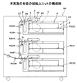
図7は、本実施の形態の給紙装置を備えた給紙ユニットの一例を示す構成図である。給紙ユニット90は、図1等に示す用紙収納部20を構成する複数の用紙トレイ、本例では3個の用紙トレイP220,P221,P222が上下方向に備えられる。また、各々の用紙トレイP220,P221,P222上には、図1等に示す搬送ベルト30等を有した吸着搬送機構3が備えられる。
<Configuration Example of Paper Feed Unit of the Present Embodiment>
FIG. 7 is a configuration diagram illustrating an example of a paper feeding unit including the paper feeding device according to the present embodiment. The
更に、各用紙トレイP220,P221,P222の側方に図7では図示されない吹出口昇降機構で昇降する浮上エア吹出口40を有し、用紙トレイP220,P221,P222に積載された用紙Pの側方から浮上エアを吹きつける浮上エア送風機構4が備えられる。また、吸着搬送機構3で2枚以上の用紙Pが吸着された場合に、最上位の1枚の用紙と2枚目以降の用紙の間に分離エアを吹きつける分離エア送風機構5が備えられる。給紙ユニット90は、後述する画像形成装置の制御部に制御されるが、図1等で説明した吸着検知センサ6と給紙検知センサ39の出力に基づいて、浮上エア吹出口40の昇降制御等を行う制御部を、給紙ユニット90に備えても良い。
Further, the side of each paper tray P220, P221, P222 has a floating
用紙トレイP220,P221,P222は、図面の手前側に設けられる図示しない正面扉を開けて、図の前後方向に引き出し可能に設けられている。なお、用紙トレイの前面を外装板として構成するとともに、外装板に手が掛けられる取手等を備え、取手等を利用して用紙トレイの引き出し及び押し込みを行うように構成することもできる。 The paper trays P220, P221, and P222 are provided so that they can be pulled out in the front-rear direction of the drawing by opening a front door (not shown) provided on the front side of the drawing. In addition, the front surface of the paper tray can be configured as an exterior plate, and a handle or the like that can be put on the exterior plate can be provided, and the paper tray can be pulled out and pushed in using the handle or the like.
吸着搬送機構3による用紙Pの給紙方向は、各用紙トレイP220,P221,P222の引き出し方向と直交する方向(図における左側方向)である。
The paper feeding direction of the paper P by the
吸着搬送機構3で搬送ベルト30に吸着される用紙Pは、浮上エア送風機構4から吹き出される浮上エアと分離エア送風機構5から吹き出される分離エア等の作用で1枚に分離される。吸着搬送機構3により用紙トレイP220から繰り出される用紙Pは、図1に示す第2の従動ローラ群33の下側の従動ローラに巻きつけられた搬送ベルト30の下面と略同じ高さにニップ部を有した一対の搬送ローラ37及び従動ローラ38に挟持される。
The sheet P adsorbed to the
搬送ローラ37と従動ローラ38に挟持された用紙Pは、搬送ローラ37により搬送されるとともに、ガイド部材の作用で下向きに搬送方向が変えられる。次に、垂直方向の用紙搬送路を構成する搬送ローラR223〜R227により下方に搬送され、ガイド部材で図の左側略水平方向にガイドされた後、回転停止状態にある搬送ローラR228に先端を当接して停止される。
The paper P sandwiched between the
搬送ローラR228は、後述する画像形成装置10における画像形成プロセスとのタイミングをとるためのレジストローラとしての機能を果たしている。その後、搬送ローラ228等の回転開始に伴って、用紙Pは画像形成装置内に送り込まれる。 The conveyance roller R228 functions as a registration roller for taking a timing with an image forming process in the image forming apparatus 10 to be described later. Thereafter, the paper P is fed into the image forming apparatus with the start of rotation of the transport roller 228 and the like.
同様に、吸着搬送機構3により用紙トレイP221から繰り出される用紙Pは、図1に示す第2の従動ローラ群33の下側の従動ローラに巻きつけられた搬送ベルト30の下面と略同じ高さにニップ部を有した一対の搬送ローラ37及び従動ローラ38に挟持される。
Similarly, the sheet P fed from the sheet tray P221 by the
搬送ローラ37と従動ローラ38に挟持された用紙Pは、搬送ローラ37により搬送されるとともに、ガイド部材の作用で下向きに搬送方向が変えられる。次に、搬送ローラR226,R227により下方に搬送され、ガイド部材で図の左側略水平方向にガイドされた後、回転停止状態にある搬送ローラR228に先端を当接して停止され、搬送ローラR228の回転開始に伴って画像形成装置内に送り込まれる。
The paper P sandwiched between the
更に、吸着搬送機構3により用紙トレイP222から繰り出される用紙Pは、図1に示す第2の従動ローラ群33の下側の従動ローラに巻きつけられた搬送ベルト30の下面と略同じ高さにニップ部を有した一対の搬送ローラ37及び従動ローラ38に挟持される。
Further, the sheet P fed out from the sheet tray P222 by the
搬送ローラ37と従動ローラ38に挟持された用紙Pは、搬送ローラ37により搬送されるとともに、回転停止状態にある搬送ローラR228に先端を当接した状態で停止され、搬送ローラR228の回転開始に従って画像形成装置内に送り込まれる。
The paper P sandwiched between the
<本実施の形態の画像形成装置の構成例>
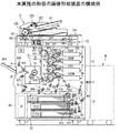
図8は、本実施の形態の給紙装置を備えた給紙ユニットが接続される画像形成装置の一例を示す構成図である。画像形成装置10は、例えばデジタルカラー複写機で、装置本体上部に自動原稿搬送装置11を備えると共に、内部に画像読み取り部12、画像形成部13、ベルトユニット14、給紙部15、定着装置T、反転排紙部16、及び再給紙部17を備える。
<Example of Configuration of Image Forming Apparatus of Embodiment>
FIG. 8 is a configuration diagram illustrating an example of an image forming apparatus to which a paper feeding unit including the paper feeding device of the present embodiment is connected. The image forming apparatus 10 is, for example, a digital color copier, and includes an
自動原稿搬送装置11は、原稿を1枚ずつ送り出して画像読み取り位置へと搬送し、画像読み取りが終わった原稿を原稿排紙トレイに排紙する。
The
自動原稿搬送装置11は、原稿載置トレイ101、原稿分離部103、原稿搬送部105、原稿排紙部107、原稿排紙トレイ109、及び原稿の表裏面を反転するための原稿反転ローラ111を備える。
The
原稿載置トレイ101上に載置された複数枚の原稿は、原稿分離部103により1枚づつ分離され、原稿搬送部105を介して画像読み取り位置へ搬送される。
A plurality of originals placed on the
原稿読み取り位置は、原稿搬送部105の下流側に設けられており、画像読み取り部12のスリット201を介して、原稿の画像が読み取られ、読み取られた原稿は原稿排紙部107によって原稿排紙トレイ109上へ排紙される。なお、両面読み取りにおいては、片面が読み取られた原稿は、原稿反転ローラ111により二点鎖線の矢印で示す方向へ搬送される。
The document reading position is provided on the downstream side of the
そして、進行方向における原稿の後端を挟持された状態で停止された後、原稿反転ローラ111の逆回転により、原稿搬送部105を介して再び画像読み取り位置へ搬送される。その後、原稿排紙部107によって原稿排紙トレイ109上へ排紙される。
Then, after the document is stopped in a state where the trailing edge of the document in the advancing direction is held, the document reversing roller 111 is reversely rotated and conveyed again to the image reading position via the
上述した工程は、原稿載置トレイ101上に載置された複数枚の原稿について繰り返される。
The above-described process is repeated for a plurality of documents placed on the
画像読み取り部12は、上述したスリット201、原稿照射用のランプ213及び原稿の反射光を反射させる第1ミラー215を一体化した第1ミラーユニット205と、第2ミラー217及び第3ミラー219とを一体化した第2ミラーユニット207とを備える。
The
また、第3ミラー219からの反射光を撮像素子上に結像させる結像レンズ209、及び結像レンズ209によって結像された光像を光電変換して画像情報を得るライン状の撮像素子(以下、CCDという)211を備える。
In addition, an
自動原稿搬送装置11によって搬送される原稿を、画像読み取り部12で読み取る態様においては、第1ミラーユニット205及び第2ミラーユニット207は、図示の位置に固定されている。
In a mode in which the document conveyed by the automatic
画像読み取り部12によって読み取られた画像情報は、適宜の画像処理を施された後、一旦、制御部のメモリに記憶される。画像読み取り部12によって読み取られ、メモリに記憶された各色の画像情報は、メモリから順次読み出され、各色毎の画像形成部13にそれぞれ電気信号として送信される。
The image information read by the
画像形成部13は、色分解画像に応じたトナー像を形成するイエロー(Y)、マゼンタ(M)、シアン(C)、黒(BK)の4組の画像形成ユニット130(130Y、130M、130C、130BK)を備える。
The
各々の画像形成ユニット130は、感光層をドラム状の金属基体上に設けた感光体310、帯電器320、画像書き込み手段である露光光学系330、現像装置340、一次転写部350、クリーニング部360を主要構成要素とする。なお、露光光学系330は、レーザ光学系で構成される露光ユニットである。
Each image forming unit 130 includes a
図8においては、イエロー(Y)の画像形成ユニットを構成する部材にのみ参照符号を付し、他の画像形成ユニットは同様の構成を有するため参照符号を省略する。 In FIG. 8, only members constituting the yellow (Y) image forming unit are provided with reference numerals, and the other image forming units have the same configuration, and thus the reference numerals are omitted.
現像装置340は、キャリアとトナーとを含む二成分現像剤を収納する。また、現像装置340は、固定された複数の磁石を内蔵する円筒状の非磁性の現像スリーブと、現像剤収納部と、トナー濃度検知センサを備える。
The developing
現像剤は、複数の磁石の作用により現像スリーブ上に磁気的に担持され、当該現像スリーブの回転によって現像領域に搬送され、次いで、現像処理後の現像剤は、反発磁界の作用により現像スリーブ上から除去される。また、現像スリーブには、所定の極性(ここではマイナス極性)の直流電圧と交流電圧を重畳したバイアス電圧が印加される。 The developer is magnetically supported on the developing sleeve by the action of a plurality of magnets, and is conveyed to the developing area by the rotation of the developing sleeve. Next, the developer after the development processing is applied to the developing sleeve by the action of a repulsive magnetic field. Removed from. In addition, a bias voltage in which a DC voltage having a predetermined polarity (here, negative polarity) and an AC voltage are superimposed is applied to the developing sleeve.
一次転写部350は、中間転写ベルト401を介して感光体310の周面に対向している一次転写ローラからなる。
The
クリーニング部360は、一次転写後の感光体310上に残留するトナーを除去し、除去されたトナーを、用紙トレイの側部に設置されている廃トナーボックスDTに収納する。
The
各色の画像形成ユニット130は、縦方向に配設された中間転写ベルト401の一平面Aの進行方向に沿って、上から、イエロー(Y)、マゼンタ(M)、シアン(C)、黒(BK)の順に配置されている。
The image forming units 130 of the respective colors have yellow (Y), magenta (M), cyan (C), and black (from the top) along the traveling direction of one plane A of the
ベルトユニット14は、上述した中間転写ベルト401と、当該中間転写ベルトを懸架する支持ローラ405、406、407、及びバックアップローラ410等により構成される。
The
また、転写ローラ510は、中間転写ベルト401を挟んで対向配置され、転写ローラ510を圧接して回転するバックアップローラ410とで二次転写部が構成される。
Further, the
画像形成装置10における画像形成プロセスは次のように行われる。図8中反時計方向に回転する感光体310の表面が、帯電器320により所定の極性(ここではマイナス極性)に帯電される。
The image forming process in the image forming apparatus 10 is performed as follows. The surface of the
次いで、露光光学系330による第1の色信号、即ち、イエロー(Y)の画像信号に対応する露光が施され、当該イエロー(Y)の画像に対応する潜像が感光体310上に形成される。
Next, the exposure
感光体310の潜像は、現像装置340の現像剤により接触または非接触にて反転現像され、感光体310上にイエロー(Y)のトナー像が形成された後、一次転写部350によって中間転写ベルト401上に一次転写される。
The latent image on the
第1の色信号による画像形成開始から所定時間後に順次開始される他の色信号による画像形成プロセスは、イエローの場合と同様に、マゼンタ(M)、シアン(C)、黒(BK)の各色の画像形成ユニット130によって行われる。 The image forming process using other color signals sequentially started after a predetermined time from the start of image forming using the first color signal is the same for each color of magenta (M), cyan (C), and black (BK) as in the case of yellow. This is performed by the image forming unit 130.
各色の感光体310上に形成された各色のトナー像は、中間転写ベルト401上に重ね合わせて二次転写され、中間転写ベルト401上にカラートナー像が形成される。一方、一次転写処理終了後の感光体310の表面はクリーニング部360で清掃される。
The toner images of the respective colors formed on the
なお、感光体310、あるいは、中間転写ベルト401に対する個々の画像形成プロセスの開始タイミングは次のように行われる。すなわち、中間転写ベルト401の外側であって、中間転写ベルトの回転方向に見て、転写ローラ510のある位置からイエローの画像形成ユニットを設けている位置までの区間にレジストセンサ413を備える。
Note that the start timing of each image forming process for the
そして、中間転写ベルト401に設けた基準マークをレジストセンサ413が検知した時を起点として計時を行い、所定時間経過毎に、順次、(Y)、(M)、(C)、(BK)の画像形成プロセスを開始する。
Then, the time is measured starting from the time when the
制御部Sは、演算制御処理を行うCPUと、各種プログラムを記憶しているROM、各種データを記憶するRAM等を有し、一連の画像形成プロセスに係わる制御等の全ての制御を行う。制御部Sは、図1等で説明した吸着検知センサ6と給紙検知センサ39の出力に基づいて、給紙ユニット90の浮上エア吹出口40の昇降制御等を行う。
The control unit S includes a CPU that performs arithmetic control processing, a ROM that stores various programs, a RAM that stores various data, and the like, and performs all controls such as control related to a series of image forming processes. The control unit S performs up-and-down control of the floating
画像形成装置10は、装置本体の下部に3つの用紙トレイP11,P12,P13を備える。各用紙トレイP11,P12,P13に、上述した搬送ベルト30等を有した吸着搬送機構3と、浮上エア送風機構4と分離エア送風機構5等を備えても良い。制御部S1は、図1等で説明した吸着検知センサ6と給紙検知センサ39の出力に基づいて、各用紙トレイP11,P12,P13に備えられた浮上エア吹出口40の昇降制御等を行う。各用紙トレイP11,P12,P13は、図の手前方向に引き出し可能である。
The image forming apparatus 10 includes three paper trays P11, P12, and P13 at the lower part of the apparatus main body. Each of the paper trays P11, P12, and P13 may include the
用紙トレイP11,P12,P13は、給紙ローラ503,513,523、分離ローラ506,516,526、及び搬送ローラR1,R2,R3を備え、これらローラで送り出された用紙Pは、搬送ローラR4〜R7によって搬送される。
The paper trays P11, P12, and P13 include
レジストローラ59は、搬送ローラR7よりも下流であって、二次転写部に近接した位置に設けられている。また、搬送路上の二次転写部より下流に、加熱源を内蔵した定着ローラT1と、定着ローラT1と圧接して回転する加圧ローラT2を有する定着装置Tが配置されている。 The registration roller 59 is provided downstream of the conveyance roller R7 and at a position close to the secondary transfer unit. Further, a fixing device T having a fixing roller T1 having a built-in heating source and a pressure roller T2 rotating in pressure contact with the fixing roller T1 is disposed downstream of the secondary transfer portion on the conveyance path.
排紙ローラ600は、画像形成された用紙Pを排紙する。排紙トレイ650は、排紙ローラ600で排紙された用紙Pが積載される。
The
反転排紙部16は、排紙される用紙Pを反転搬送して排紙する。再給紙部17は、片面に画像形成された用紙を反転搬送し、レジストローラ59へ用紙を再給紙する。
The reverse
次に、中間転写ベルト401上に形成されたカラートナー像が用紙上に転写され、装置外に排紙されるまでの工程と関連して、装置のその他の構成について簡単に説明する。
Next, other configurations of the apparatus will be briefly described in relation to the process from when the color toner image formed on the
中間転写ベルト401上における画像形成に対応した適宜のタイミングで、用紙Pが給紙ローラ503(513、523)によって給紙される。給紙される用紙Pは、枚数、開始釦、倍率又は画像濃度等を設定することができる操作表示部150上で選択されたサイズの用紙であり、装置内の用紙トレイP11,P12,P13、または、給紙ユニット90の用紙トレイP220,P221,P222から給紙される。
The paper P is fed by the paper feed rollers 503 (513 and 523) at an appropriate timing corresponding to image formation on the
次に、用紙Pは、分離ローラ506、及び搬送経路上に設けた複数の搬送ローラR1〜R7により挟持搬送されて、二次転写部の上流側に設けられているレジストローラ59へ搬送される。
Next, the sheet P is nipped and conveyed by the
用紙Pは、レジストローラ59に先端が当接された後、当該レジストローラ59の回転再開により、中間転写ベルト401上のカラートナー像領域と重畳するタイミングで給紙される。
After the leading end of the sheet P comes into contact with the registration roller 59, the sheet P is fed at a timing overlapping with the color toner image area on the
次に、用紙Pは、二次転写部においてバックアップローラ410と転写ローラ510により中間転写ベルト401と共に押圧挟持され、この間に、中間転写ベルト401上のカラートナー像が用紙P上に二次転写される。二次転写の際、転写ローラ510に所定の転写バイアス電圧を印加することが望ましい。カラートナー像が転写された用紙Pは、中間転写ベルト401から分離され、図示しない搬送ベルトにより定着装置Tへ搬送され、加熱及び加圧処理によりカラートナーが溶融され、用紙P上に定着される。
Next, the paper P is pressed and nipped together with the
定着装置Tによる定着処理後の用紙Pは、下流に設けた排紙ローラ600により搬送され、装置本体外の排紙トレイ650上に排紙される。一方、二次転写後の中間転写ベルト401の表面は、クリーニング部360によりクリーニングされ、次のカラートナー像の転写工程が行われる。
The paper P after the fixing process by the fixing device T is conveyed by a
図8において、切替部材601の位置は、定着処理後に用紙Pを反転することなく排紙する場合の位置である。用紙Pを反転排紙する時は、切替部材601が所定量回動され、定着処理後の用紙Pは切替部材601の右辺に沿って下方に案内される。
In FIG. 8, the position of the switching
次に、反転ローラ602によって後端が挟持された状態で停止された後、当該反転ローラ602の逆回転により、用紙Pは切替部材601の左側の辺に沿って上昇され、排紙ローラ600を介して排紙される。
Next, after the paper is stopped with the rear end being nipped by the
更に、再給紙部17を用いる両面コピーモードの場合、片面に画像が形成された定着処理後の用紙Pは切替部材601の右側の辺に沿って下方に案内され、用紙Pの後端が反転ローラ605により挟持された状態で停止される。
Further, in the double-sided copy mode using the
次に、反転ローラ605を逆回転させ、図示しないガイド板に沿って上昇させ、複数のローラ701、702、703に搬送され用紙Pを反転搬送する。
Next, the
用紙Pの第2面に対する画像形成プロセスは前述と同様であり、また、定着装置Tから送り出された後の排出路については前述した何れかが選択される。
一方、感光体上からクリーニング部360により除去されたトナーは、廃トナーボックスDTに送られて収納される。なお、以上はカラー画像を形成する画像形成装置であったが、モノクロ画像を形成する画像形成装置であっても良い。
The image forming process for the second surface of the paper P is the same as described above, and any of the discharge paths after being sent out from the fixing device T is selected.
On the other hand, the toner removed from the photoreceptor by the
本発明は、積載された用紙をエアで浮上させて搬送ベルト等に吸着させる給紙装置を備えた画像形成装置に適用される。 The present invention is applied to an image forming apparatus including a paper feeding device that floats stacked paper with air and sucks it on a conveyance belt or the like.
1A・・・給紙装置、2・・・用紙載置台、20・・・用紙収納部、22・・・上限検知センサ、3・・・吸着搬送機構、30・・・搬送ベルト、39・・・給紙検知センサ、4・・・浮上エア送風機構、40・・・浮上エア吹出口、41・・・送風ファン、42・・・吹出口形成ダクト、43・・・吹出口昇降機構、5・・・分離エア送風機構、6・・・吸着検知センサ、S1・・・制御部 DESCRIPTION OF SYMBOLS 1A ... Paper feeder, 2 ... Paper mounting stand, 20 ... Paper storage part, 22 ... Upper limit detection sensor, 3 ... Adsorption conveyance mechanism, 30 ... Conveyance belt, 39 ... Paper feed detection sensor, 4 ... floating air blowing mechanism, 40 ... floating air blowing outlet, 41 ... blowing fan, 42 ... blowing outlet forming duct, 43 ... blowing outlet lifting mechanism, 5 ... Separate air blowing mechanism, 6 ... Suction detection sensor, S1 ... Control unit
Claims (5)
前記用紙載置台に積載された用紙を上面から吸引し、最上位の用紙を吸着面に吸着すると共に、前記吸着面に吸着された用紙を用紙搬送路に搬送する吸着搬送機構と、
前記用紙載置台に積載された用紙が前記吸着面に向けて浮上する方向に沿って昇降する空気吹出口を有し、前記空気吹出口から用紙の側方に向けて空気を吹き出す送風機構と、
前記空気吹出口を、前記用紙載置台に積載される用紙の側方に対向する第1の位置と前記吸着面に吸着された用紙の側方に対向する第2の位置に移動させる吹出口昇降機構と、
前記吸着面に用紙が吸着されたか否かを検知する吸着検知センサと、
前記吸着搬送機構で搬送される用紙を検知する給紙検知センサと、
前記吸着検知センサで検知される前記吸着面への用紙の吸着の有無、及び前記給紙検知センサで検知される用紙の搬送位置に基づいて、前記用紙載置台に積載された用紙を浮上させる浮上動作タイミング、及び前記吸着搬送機構で前記吸着面に吸着された用紙を分離する分離動作タイミングを判断し、動作タイミングの判断結果に基づき前記吹出口昇降機構を制御して、浮上動作タイミングで前記空気吹出口を第1の位置に移動させ、分離動作タイミングで前記空気吹出口を第2の位置に移動させる制御部と
を備えたことを特徴とする給紙装置。 A paper mounting table on which a plurality of paper sheets are stacked and moved up and down along the paper stacking direction;
A suction conveyance mechanism that sucks the paper stacked on the paper placement table from the upper surface, sucks the uppermost paper to the suction surface, and transports the paper sucked on the suction surface to the paper transport path;
A blower mechanism that has an air outlet that moves up and down along a direction in which the paper loaded on the paper placement table floats toward the suction surface, and blows air from the air outlet toward the side of the paper;
Elevating and lowering the air outlet that moves the air outlet to a first position that faces the side of the paper loaded on the paper mounting table and a second position that faces the side of the paper sucked by the suction surface Mechanism,
An adsorption detection sensor for detecting whether or not a sheet is adsorbed on the adsorption surface;
A paper feed detection sensor for detecting paper conveyed by the suction conveyance mechanism;
Floating that floats the paper loaded on the paper mounting table based on whether or not the paper is attracted to the suction surface detected by the suction detection sensor and the paper transport position detected by the paper feed detection sensor The operation timing and the separation operation timing for separating the sheet adsorbed on the suction surface by the suction conveyance mechanism are determined, and the air outlet lifting mechanism is controlled based on the determination result of the operation timing, and the air is moved at the floating operation timing. And a control unit that moves the air outlet to the first position and moves the air outlet to the second position at the separation operation timing.
前記吸着検知センサで前記吸着面に用紙が吸着されたことを検知しているとき、または、前記吸着検知センサで前記吸着面に用紙が吸着されたことを検知している間に、前記給紙検知センサで用紙が非検知となったときは、分離動作タイミングであると判断して、前記空気吹出口を第2の位置に移動させ、
前記吸着検知センサで前記吸着面に用紙が未吸着であることを検知しているとき、または、前記吸着検知センサで前記吸着面に用紙が吸着されたことを検知している間に、前記給紙検知センサで用紙を検知したときは、浮上動作タイミングであると判断して、前記空気吹出口を第1の位置に移動させる
ことを特徴とする請求項1記載の給紙装置。 The controller is
When the suction detection sensor detects that the paper is sucked on the suction surface, or while the suction detection sensor detects that the paper is sucked on the suction surface, the paper feed When the paper is not detected by the detection sensor, it is determined that it is the separation operation timing, and the air outlet is moved to the second position.
While the suction detection sensor detects that the sheet is not attracted to the suction surface, or while the suction detection sensor detects that the sheet is sucked to the suction surface, The paper feeding device according to claim 1, wherein when the paper is detected by the paper detection sensor, it is determined that it is a floating operation timing, and the air outlet is moved to the first position.
ことを特徴とする請求項1または2記載の給紙装置。 3. The sheet feeding member according to claim 1, further comprising a sheet pressing member that protrudes at a length in contact with a side portion of the sheet that floats on the air blown out from the air blowing port at an upper portion of the air blowing port. Paper device.
前記用紙トレイで複数枚の用紙が積載され、用紙の積載方向に沿って昇降する用紙載置台と、
前記用紙載置台に積載された用紙を上面から吸引し、最上位の用紙を吸着面に吸着すると共に、前記吸着面に吸着された用紙を用紙搬送路に搬送する吸着搬送機構と、
前記用紙載置台に積載された用紙が前記吸着面に向けて浮上する方向に沿って昇降する空気吹出口を有し、前記空気吹出口から用紙の側方に向けて空気を吹き出す送風機構と、
前記空気吹出口を、前記用紙載置台に積載される用紙の側方に対向する第1の位置と前記吸着面に吸着された用紙の側方に対向する第2の位置に移動させる吹出口昇降機構と、
前記吸着面に用紙が吸着されたか否かを検知する吸着検知センサと、
前記吸着搬送機構で搬送される用紙を検知する給紙検知センサと、
前記吸着検知センサで検知される前記吸着面への用紙の吸着の有無、及び前記給紙検知センサで検知される用紙の搬送位置に基づいて、前記用紙載置台に積載された用紙を浮上させる浮上動作タイミング、及び前記吸着搬送機構で前記吸着面に吸着された用紙を分離する分離動作タイミングを判断し、動作タイミングの判断結果に基づき前記吹出口昇降機構を制御して、浮上動作タイミングで前記空気吹出口を第1の位置に移動させ、分離動作タイミングで前記空気吹出口を第2の位置に移動させる制御部と
を備えたことを特徴とする給紙ユニット。 One or more paper trays in which paper is stored;
A plurality of sheets stacked on the sheet tray, and a sheet placing table that moves up and down along the sheet stacking direction;
A suction conveyance mechanism that sucks the paper stacked on the paper placement table from the upper surface, sucks the uppermost paper to the suction surface, and transports the paper sucked on the suction surface to the paper transport path;
A blower mechanism that has an air outlet that moves up and down along a direction in which the paper loaded on the paper placement table floats toward the suction surface, and blows air from the air outlet toward the side of the paper;
Elevating and lowering the air outlet that moves the air outlet to a first position that faces the side of the paper loaded on the paper mounting table and a second position that faces the side of the paper sucked by the suction surface Mechanism,
An adsorption detection sensor for detecting whether or not a sheet is adsorbed on the adsorption surface;
A paper feed detection sensor for detecting paper conveyed by the suction conveyance mechanism;
Floating that floats the paper loaded on the paper mounting table based on whether or not the paper is attracted to the suction surface detected by the suction detection sensor and the paper transport position detected by the paper feed detection sensor The operation timing and the separation operation timing for separating the sheet adsorbed on the suction surface by the suction conveyance mechanism are determined, and the air outlet lifting mechanism is controlled based on the determination result of the operation timing, and the air is moved at the floating operation timing. And a control unit that moves the air outlet to the first position and moves the air outlet to the second position at the separation operation timing.
前記画像形成部に用紙を給紙する給紙装置と、
前記給紙装置から前記画像形成部に用紙を給紙し、前記画像形成部で画像を形成する制御を行う制御部とを備え、
前記給紙装置は、
複数枚の用紙が積載され、用紙の積載方向に沿って昇降する用紙載置台と、
前記用紙載置台に積載された用紙を上面から吸引し、最上位の用紙を吸着面に吸着すると共に、前記吸着面に吸着された用紙を用紙搬送路に搬送する吸着搬送機構と、
前記用紙載置台に積載された用紙が前記吸着面に向けて浮上する方向に沿って昇降する空気吹出口を有し、前記空気吹出口から用紙の側方に向けて空気を吹き出す送風機構と、
前記空気吹出口を、前記用紙載置台に積載される用紙の側方に対向する第1の位置と前記吸着面に吸着された用紙の側方に対向する第2の位置に移動させる吹出口昇降機構と、
前記吸着面に用紙が吸着されたか否かを検知する吸着検知センサと、
前記吸着搬送機構で搬送される用紙を検知する給紙検知センサとを備え、
前記制御部は、前記吸着検知センサで検知される前記吸着面への用紙の吸着の有無、及び前記給紙検知センサで検知される用紙の搬送位置に基づいて、前記用紙載置台に積載された用紙を浮上させる浮上動作タイミング、及び前記吸着搬送機構で前記吸着面に吸着された用紙を分離する分離動作タイミングを判断し、動作タイミングの判断結果に基づき前記吹出口昇降機構を制御して、浮上動作タイミングで前記空気吹出口を第1の位置に移動させ、分離動作タイミングで前記空気吹出口を第2の位置に移動させる
ことを特徴とする画像形成装置。 An image forming unit for forming an image on paper;
A paper feeding device for feeding paper to the image forming unit;
A control unit that performs control to feed a sheet from the sheet feeding device to the image forming unit and form an image in the image forming unit;
The paper feeder is
A paper mounting table on which a plurality of paper sheets are stacked and moved up and down along the paper stacking direction;
A suction conveyance mechanism that sucks the paper stacked on the paper placement table from the upper surface, sucks the uppermost paper to the suction surface, and transports the paper sucked on the suction surface to the paper transport path;
A blower mechanism that has an air outlet that moves up and down along a direction in which the paper loaded on the paper placement table floats toward the suction surface, and blows air from the air outlet toward the side of the paper;
Elevating and lowering the air outlet that moves the air outlet to a first position that faces the side of the paper loaded on the paper mounting table and a second position that faces the side of the paper sucked by the suction surface Mechanism,
An adsorption detection sensor for detecting whether or not a sheet is adsorbed on the adsorption surface;
A paper feed detection sensor for detecting paper transported by the suction transport mechanism,
The control unit is loaded on the paper mounting table based on the presence / absence of paper suction to the suction surface detected by the suction detection sensor and the paper transport position detected by the paper feed detection sensor. The floating operation timing for floating the paper and the separation operation timing for separating the paper adsorbed on the suction surface by the suction conveyance mechanism are determined, and the blow-up and lowering mechanism is controlled based on the determination result of the operation timing. The image forming apparatus, wherein the air blower outlet is moved to a first position at an operation timing, and the air blower outlet is moved to a second position at a separation operation timing.
Priority Applications (2)
| Application Number | Priority Date | Filing Date | Title |
|---|---|---|---|
| JP2008319555A JP5245796B2 (en) | 2008-12-16 | 2008-12-16 | Paper feeding device, paper feeding unit, and image forming apparatus |
| US12/635,810 US8002265B2 (en) | 2008-12-16 | 2009-12-11 | Sheet supply apparatus, sheet supply unit and image forming apparatus |
Applications Claiming Priority (1)
| Application Number | Priority Date | Filing Date | Title |
|---|---|---|---|
| JP2008319555A JP5245796B2 (en) | 2008-12-16 | 2008-12-16 | Paper feeding device, paper feeding unit, and image forming apparatus |
Publications (2)
| Publication Number | Publication Date |
|---|---|
| JP2010143652A true JP2010143652A (en) | 2010-07-01 |
| JP5245796B2 JP5245796B2 (en) | 2013-07-24 |
Family
ID=42239558
Family Applications (1)
| Application Number | Title | Priority Date | Filing Date |
|---|---|---|---|
| JP2008319555A Expired - Fee Related JP5245796B2 (en) | 2008-12-16 | 2008-12-16 | Paper feeding device, paper feeding unit, and image forming apparatus |
Country Status (2)
| Country | Link |
|---|---|
| US (1) | US8002265B2 (en) |
| JP (1) | JP5245796B2 (en) |
Cited By (3)
| Publication number | Priority date | Publication date | Assignee | Title |
|---|---|---|---|---|
| JP2015009973A (en) * | 2013-07-01 | 2015-01-19 | 株式会社リコー | Sheet conveying device and image forming apparatus |
| JP2019081641A (en) * | 2017-10-31 | 2019-05-30 | 理想科学工業株式会社 | Sheet feeding device |
| JP2022179999A (en) * | 2021-05-24 | 2022-12-06 | 富士フイルムビジネスイノベーション株式会社 | Sheet media feeder and use device |
Families Citing this family (11)
| Publication number | Priority date | Publication date | Assignee | Title |
|---|---|---|---|---|
| US7458570B2 (en) * | 2004-09-13 | 2008-12-02 | Ricoh Printing Systems, Ltd. | Sheet-supplying device |
| JP5298794B2 (en) * | 2008-11-18 | 2013-09-25 | コニカミノルタ株式会社 | Paper feeding device and image forming apparatus |
| JP2010269922A (en) * | 2009-05-25 | 2010-12-02 | Konica Minolta Business Technologies Inc | Paper feeder, image forming device and image forming system |
| US8800753B2 (en) * | 2009-09-10 | 2014-08-12 | Bdt Media Automation Gmbh | System for conveying an article using vortex suction units |
| JP2011184179A (en) * | 2010-03-10 | 2011-09-22 | Ricoh Co Ltd | Paper feeder and image forming device |
| US9079733B2 (en) | 2010-05-07 | 2015-07-14 | Bdt Media Automation Gmbh | Vortex suction separator device |
| US8186668B2 (en) * | 2010-10-07 | 2012-05-29 | Bdt Ag | Stack feeding aeration device and method |
| JP2013230926A (en) * | 2012-05-01 | 2013-11-14 | Fuji Xerox Co Ltd | Sheet feeding device, sheet containing device, and image forming apparatus |
| JP6443724B2 (en) * | 2013-12-16 | 2018-12-26 | 株式会社リコー | Paper feeding device, image forming apparatus, and image forming system |
| US11059687B2 (en) * | 2017-10-31 | 2021-07-13 | Riso Kagaku Corporation | Sheet supplying device |
| US10233042B1 (en) * | 2018-01-22 | 2019-03-19 | Xerox Corporation | Top vacuum corrugation feeder with adjustable fluffer nozzles for enhanced feeding of specialty sheets |
Citations (6)
| Publication number | Priority date | Publication date | Assignee | Title |
|---|---|---|---|---|
| JPH0372538U (en) * | 1989-11-09 | 1991-07-22 | ||
| JPH07133030A (en) * | 1993-11-10 | 1995-05-23 | Canon Inc | Paper feeding device and image forming apparatus including the paper feeding device |
| JP2004131291A (en) * | 2002-09-20 | 2004-04-30 | Canon Inc | Sheet feeding device and image forming device |
| JP2004224505A (en) * | 2003-01-22 | 2004-08-12 | Tohoku Ricoh Co Ltd | Sheet separating device, sheet feeding device and image forming apparatus |
| JP2006168933A (en) * | 2004-12-17 | 2006-06-29 | Konica Minolta Business Technologies Inc | Sheet material feeder and image forming device |
| JP2006321630A (en) * | 2005-05-20 | 2006-11-30 | Konica Minolta Business Technologies Inc | Paper feeder and image forming system |
Family Cites Families (4)
| Publication number | Priority date | Publication date | Assignee | Title |
|---|---|---|---|---|
| US3627308A (en) * | 1970-05-25 | 1971-12-14 | Eastman Kodak Co | Sheet separator |
| JPS59149250A (en) * | 1983-02-15 | 1984-08-27 | Matsushita Electric Works Ltd | Transportation apparatus for single plate |
| US6955348B2 (en) * | 2002-09-20 | 2005-10-18 | Canon Kabushiki Kaisha | Sheet feeder which separates sheets with variable speed and/or direction blown air and image forming apparatus using same |
| JP5233633B2 (en) * | 2008-12-11 | 2013-07-10 | コニカミノルタビジネステクノロジーズ株式会社 | Paper feeding device, paper feeding unit, and image forming apparatus |
-
2008
- 2008-12-16 JP JP2008319555A patent/JP5245796B2/en not_active Expired - Fee Related
-
2009
- 2009-12-11 US US12/635,810 patent/US8002265B2/en active Active
Patent Citations (6)
| Publication number | Priority date | Publication date | Assignee | Title |
|---|---|---|---|---|
| JPH0372538U (en) * | 1989-11-09 | 1991-07-22 | ||
| JPH07133030A (en) * | 1993-11-10 | 1995-05-23 | Canon Inc | Paper feeding device and image forming apparatus including the paper feeding device |
| JP2004131291A (en) * | 2002-09-20 | 2004-04-30 | Canon Inc | Sheet feeding device and image forming device |
| JP2004224505A (en) * | 2003-01-22 | 2004-08-12 | Tohoku Ricoh Co Ltd | Sheet separating device, sheet feeding device and image forming apparatus |
| JP2006168933A (en) * | 2004-12-17 | 2006-06-29 | Konica Minolta Business Technologies Inc | Sheet material feeder and image forming device |
| JP2006321630A (en) * | 2005-05-20 | 2006-11-30 | Konica Minolta Business Technologies Inc | Paper feeder and image forming system |
Cited By (5)
| Publication number | Priority date | Publication date | Assignee | Title |
|---|---|---|---|---|
| JP2015009973A (en) * | 2013-07-01 | 2015-01-19 | 株式会社リコー | Sheet conveying device and image forming apparatus |
| JP2019081641A (en) * | 2017-10-31 | 2019-05-30 | 理想科学工業株式会社 | Sheet feeding device |
| JP7101467B2 (en) | 2017-10-31 | 2022-07-15 | 理想科学工業株式会社 | Seat supply device |
| JP2022179999A (en) * | 2021-05-24 | 2022-12-06 | 富士フイルムビジネスイノベーション株式会社 | Sheet media feeder and use device |
| JP7679697B2 (en) | 2021-05-24 | 2025-05-20 | 富士フイルムビジネスイノベーション株式会社 | Sheet media supply and use device |
Also Published As
| Publication number | Publication date |
|---|---|
| US20100148419A1 (en) | 2010-06-17 |
| JP5245796B2 (en) | 2013-07-24 |
| US8002265B2 (en) | 2011-08-23 |
Similar Documents
| Publication | Publication Date | Title |
|---|---|---|
| JP5245796B2 (en) | Paper feeding device, paper feeding unit, and image forming apparatus | |
| JP5219675B2 (en) | Sheet conveying apparatus and image forming apparatus | |
| JP5605698B2 (en) | Sheet material conveying apparatus, image reading apparatus, and image forming apparatus | |
| JP5545526B2 (en) | Paper feeding device and image forming apparatus | |
| JP2016183046A (en) | Paper feeding device and image formation apparatus | |
| JP6028990B2 (en) | Sheet material conveying apparatus, image reading apparatus, and image forming apparatus | |
| US8246040B2 (en) | Sheet feeding apparatus and image forming apparatus | |
| JP6025408B2 (en) | Image forming apparatus | |
| JP2018070355A (en) | Paper feeder | |
| JP5176906B2 (en) | Paper feeding device, paper feeding unit, and image forming apparatus | |
| US10144601B2 (en) | Sheet feeding device and sheet feeding method | |
| JP2010116236A (en) | Paper feeder, paper feed unit and image forming device | |
| JP5262828B2 (en) | Paper feeding device, paper feeding unit, image forming apparatus, and image forming unit | |
| JP5163425B2 (en) | Paper feeding device, paper feeding unit, and image forming apparatus | |
| JPH09142683A (en) | Paper sheet feeder | |
| JP2009169050A (en) | Image forming apparatus | |
| JP2009227378A (en) | Paper-feeding device, box body with built-in paper-feeding device, and image forming device | |
| JP5146173B2 (en) | Image forming apparatus | |
| JP5440774B2 (en) | Recording medium supply apparatus and image forming apparatus | |
| JP2005132514A (en) | Paper feeder and image forming device equipped with the paper feeder | |
| JP2549756Y2 (en) | Image forming device | |
| JP6282566B2 (en) | Image forming apparatus | |
| JP2004010194A (en) | Sheet conveying apparatus and image forming apparatus having the same | |
| JP5741997B2 (en) | Sheet material conveying apparatus, image reading apparatus, and image forming apparatus | |
| JPH08157148A (en) | Image forming device |
Legal Events
| Date | Code | Title | Description |
|---|---|---|---|
| A621 | Written request for application examination |
Free format text: JAPANESE INTERMEDIATE CODE: A621 Effective date: 20110812 |
|
| RD02 | Notification of acceptance of power of attorney |
Free format text: JAPANESE INTERMEDIATE CODE: A7422 Effective date: 20111011 |
|
| A977 | Report on retrieval |
Free format text: JAPANESE INTERMEDIATE CODE: A971007 Effective date: 20121127 |
|
| A131 | Notification of reasons for refusal |
Free format text: JAPANESE INTERMEDIATE CODE: A131 Effective date: 20121204 |
|
| A521 | Request for written amendment filed |
Free format text: JAPANESE INTERMEDIATE CODE: A523 Effective date: 20130204 |
|
| TRDD | Decision of grant or rejection written | ||
| A01 | Written decision to grant a patent or to grant a registration (utility model) |
Free format text: JAPANESE INTERMEDIATE CODE: A01 Effective date: 20130312 |
|
| A61 | First payment of annual fees (during grant procedure) |
Free format text: JAPANESE INTERMEDIATE CODE: A61 Effective date: 20130325 |
|
| R150 | Certificate of patent or registration of utility model |
Ref document number: 5245796 Country of ref document: JP Free format text: JAPANESE INTERMEDIATE CODE: R150 Free format text: JAPANESE INTERMEDIATE CODE: R150 |
|
| FPAY | Renewal fee payment (event date is renewal date of database) |
Free format text: PAYMENT UNTIL: 20160419 Year of fee payment: 3 |
|
| S111 | Request for change of ownership or part of ownership |
Free format text: JAPANESE INTERMEDIATE CODE: R313111 |
|
| R350 | Written notification of registration of transfer |
Free format text: JAPANESE INTERMEDIATE CODE: R350 |
|
| LAPS | Cancellation because of no payment of annual fees |