JP2010143668A - Sheet stacking device and image forming device - Google Patents
Sheet stacking device and image forming device Download PDFInfo
- Publication number
- JP2010143668A JP2010143668A JP2008320303A JP2008320303A JP2010143668A JP 2010143668 A JP2010143668 A JP 2010143668A JP 2008320303 A JP2008320303 A JP 2008320303A JP 2008320303 A JP2008320303 A JP 2008320303A JP 2010143668 A JP2010143668 A JP 2010143668A
- Authority
- JP
- Japan
- Prior art keywords
- sheet
- discharge
- unit
- stacking
- sheet stacking
- Prior art date
- Legal status (The legal status is an assumption and is not a legal conclusion. Google has not performed a legal analysis and makes no representation as to the accuracy of the status listed.)
- Pending
Links
Images


Landscapes
- Pile Receivers (AREA)
Abstract
Description
本発明は、シート積載装置及び画像形成装置に関し、特に排出されたシートを良好に積載するための構成に関する。 The present invention relates to a sheet stacking apparatus and an image forming apparatus, and more particularly to a configuration for stacking discharged sheets satisfactorily.
従来、プリンタ、ファクシミリ、複写機、マルチファンクションプリンタ等の画像形成装置においては、排出された画像形成済みシートや読取済み原稿を積載する排出トレイを備えたシート積載装置が一般に知られている。このような排出トレイにシートが積載される際、排出されるシートのシート排出方向上流端(後端)が後端規制板や排出ローラにもたれてしまうことがある。そのため、排出ローラの外周部に凹凸を設け、凹凸により排出されるシートの後端を蹴り出して排出するようにしてシートの後端のもたれを防止している。 2. Description of the Related Art Conventionally, in image forming apparatuses such as printers, facsimiles, copiers, and multifunction printers, sheet stacking apparatuses that include a discharge tray on which discharged image formed sheets and read originals are stacked are generally known. When sheets are stacked on such a discharge tray, the upstream end (rear end) of the discharged sheet in the sheet discharge direction may lean against the rear end regulating plate or the discharge roller. Therefore, unevenness is provided on the outer peripheral portion of the discharge roller, and the trailing edge of the sheet discharged by the unevenness is kicked out and discharged to prevent the trailing edge of the sheet from leaning.
近年、画像形成装置は、ユーザのニーズに応じて薄紙シートから厚紙シートまで種々のシートに対応し、すべてのシートにおいて良質な画像が要求されるようになってきている。しかしながら、上述のような排出積載性を優先した排出ローラでは、特に厚紙でカラー画像が印字されたシートでは、排出ローラの外周部の凹凸により、画像面に跡を残すおそれがあった。そのため、画質と排出積載性のバランスを保つために、排出ローラ外周部の凹凸の大きさや形状等を厳しく管理する必要があった。 In recent years, image forming apparatuses are compatible with various sheets from thin paper sheets to thick paper sheets according to user needs, and high quality images have been required for all sheets. However, with the discharge roller giving priority to the discharge stackability as described above, there is a possibility that a mark may be left on the image surface due to the unevenness of the outer peripheral portion of the discharge roller, particularly in a sheet on which a color image is printed with thick paper. Therefore, in order to maintain a balance between the image quality and the discharge stackability, it is necessary to strictly manage the size and shape of the irregularities on the outer periphery of the discharge roller.
そこで、排出シートの後端もたれ対策のため、後端規制板を揺動させるようにしたものがある(特許文献1参照)。以下、図17を用いてこの方式の従来のシート積載装置について説明する。 In view of this, there is one in which the rear end regulating plate is swung to prevent the rear end of the discharge sheet from leaning (see Patent Document 1). Hereinafter, a conventional sheet stacking apparatus of this system will be described with reference to FIG.
図17において、排出ローラ対8によりシートを排出時、排出されたシートのシート排出方向上流端が後端規制板10に引っ掛かることによる後端もたれが発生しないように、後端規制板10が下端を揺動中心としてシートのシート排出方向に揺動可能になっている。
In FIG. 17, when the sheet is discharged by the discharge roller pair 8, the trailing
そして、後端規制板10が揺動することにより、排出されたシートのシート排出方向上流端をシート排出方向下流側に押し出し、排出トレイ9上にシートが良好に積載されるようにしている。
しかしながら、図17に示すような構成ではもたれ対策には十分でなく次のような問題があった。 However, the configuration as shown in FIG. 17 is not sufficient as a countermeasure against leaning and has the following problems.
薄紙シートのように腰(剛度)のないシートを排出しようとすると、図18に示すように、後端規制板10でシートを押し出そうとしてもシートが移動せず、排出ローラ対8の下側ローラにシートのシート排出方向上流端がもたれてしまうおそれがあった。このような状態になると、先行して排出されたシートが排出ローラ対8の下側ローラにもたれて排出口をふさぐことになり、後続シートの排出が妨げられたり、排出口をふさいだ先行シートの下に潜り込んだりしてしまう。この結果、排出ローラ対8から排出される後続シートがジャムしたり、先行シートが後続シートに押し出されて排出トレイ9から落下したり、シートの積載順が入れ替わったりするおそれがあった。また、排出ローラ対8の下側ローラの回転に巻き込まれて排出ローラ対8の下側ローラと後端規制板10の間の隙間から装置内部にシートが逆送されてしまうおそれもあり、シートの破損のみならず、装置の破損にもつながるおそれがある。
As shown in FIG. 18, when a sheet having no stiffness (rigidity) such as a thin paper sheet is to be discharged, the sheet does not move even if the sheet is pushed out by the rear
そこで、本発明は、このような現状に鑑みてなされたものであり、排出されるシート後端のもたれを防止してシートを排出トレイへ確実に積載することができるシート積載装置及び画像形成装置を提供することを目的とするものである。 Therefore, the present invention has been made in view of such a situation, and a sheet stacking apparatus and an image forming apparatus capable of reliably stacking a sheet on a discharge tray by preventing the trailing end of the discharged sheet from leaning. Is intended to provide.
上記目的を達成するため、本発明は、シートを排出する排出部と、前記排出部により排出されたシートを積載するシート積載部と、前記シート積載部に積載されたシートのシート排出方向上流端を規制する規制部と、前記シート積載部に積載されたシートを前記規制部に対して離間、接近する方向に移動させるシート移動手段と、を備え、前記シート移動手段は、前記シート積載部に排出されたシートを前記規制部に対して離間する方向に移動させた後、前記規制部に対して接近する方向に移動させることを特徴とする。 In order to achieve the above object, the present invention provides a discharge unit that discharges a sheet, a sheet stacking unit that stacks sheets discharged by the discharge unit, and an upstream end in the sheet discharge direction of the sheets stacked on the sheet stacking unit. And a sheet moving unit that moves the sheets stacked on the sheet stacking unit in a direction in which the sheets are separated and approached with respect to the limiting unit, and the sheet moving unit is disposed on the sheet stacking unit. The discharged sheet is moved in a direction away from the restricting portion, and then moved in a direction approaching the restricting portion.
本発明のように、シート積載部に排出されたシートを、シートの排出方向上流端を規制する規制部から遠ざけ、再び規制部に向かって移動させることにより、排出されたシートの排出方向上流端の後端もたれを防止して整列性の良好なシート積載が可能となる。 As in the present invention, the sheet discharged to the sheet stacking portion is moved away from the restricting portion that restricts the upstream end in the sheet discharge direction, and moved again toward the restricting portion, so that the upstream end in the discharge direction of the discharged sheet It is possible to prevent the trailing edge of the sheet from leaning and to stack sheets with good alignment.
以下、本発明を実施するための最良の形態を、図面を用いて詳細に説明する。ただし、この実施の形態に記載されている構成部品の寸法、材質、形状それらの相対配置などは、発明が適用される装置の構成や各種条件により適宜変更されるべきものであり、この発明の範囲を以下の実施の形態に限定する趣旨のものではない。 The best mode for carrying out the present invention will be described below in detail with reference to the drawings. However, the dimensions, materials, shapes, and relative arrangements of the components described in this embodiment should be appropriately changed according to the configuration of the apparatus to which the invention is applied and various conditions. It is not intended to limit the scope to the following embodiments.
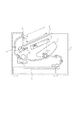
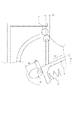
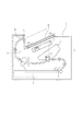
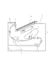
図1は、本発明の第1実施の形態に係るシート積載装置を備えた画像形成装置の一例であるレーザビームプリンタの構成を示す図である。 FIG. 1 is a diagram illustrating a configuration of a laser beam printer which is an example of an image forming apparatus provided with a sheet stacking apparatus according to a first embodiment of the present invention.
図1に示すように、本実施の形態に係るレーザビームプリンタは、感光体ドラムCd、画像情報に基づいて感光体ドラムCd上にレーザービームを照射し、静電潜像を形成するスキャナーS、シートに転写されたトナー像を定着させる定着装置T等を備えている。感光体ドラムCdは、静電潜像にトナーを付着させて顕像化する現像手段、転写後の感光体ドラムCd表面に残ったトナーを除去するクリーニング手段とともに画像形成手段を構成し、装置本体Aに着脱自在なプロセスカートリッジCに組み込まれている。 As shown in FIG. 1, the laser beam printer according to the present embodiment includes a photosensitive drum Cd, a scanner S that irradiates a laser beam on the photosensitive drum Cd based on image information, and forms an electrostatic latent image. A fixing device T for fixing the toner image transferred to the sheet is provided. The photosensitive drum Cd constitutes an image forming unit together with a developing unit that makes toner appear on the electrostatic latent image to be visualized, and a cleaning unit that removes toner remaining on the surface of the photosensitive drum Cd after transfer. The process cartridge C is detachably attached to A.
そして、カセットから給紙されたシート3がプロセスカートリッジCの感光体ドラムCdと転写ローラとで構成される転写部に搬送されてトナー画像が転写される。さらに、シート3はトナー画像が転写された後、転写部のシート排出方向下流に配設された定着装置Tに搬送され、定着装置Tによりトナー画像がシート3上に定着される。定着装置Tのシート排出方向下流には、排出部としての排出ローラ対8が配設されており、排出ローラ対8によりシート3はシート積載部を構成する排出トレイ9上に排出される。 Then, the sheet 3 fed from the cassette is transported to a transfer portion constituted by the photosensitive drum Cd of the process cartridge C and a transfer roller, and the toner image is transferred. Further, after the toner image is transferred to the sheet 3, the sheet 3 is conveyed to a fixing device T disposed downstream of the transfer unit in the sheet discharge direction, and the toner image is fixed on the sheet 3 by the fixing device T. A discharge roller pair 8 as a discharge unit is disposed downstream of the fixing device T in the sheet discharge direction. The discharge roller pair 8 discharges the sheet 3 onto a discharge tray 9 constituting a sheet stacking unit.
ここで、本実施の形態におけるシート積載部の詳細を説明する。 Here, details of the sheet stacking unit in the present embodiment will be described.
図1において、排出トレイ9は、装置本体Aの上方に設けられた排出ローラ対8から排出されたシート3を順次積載する。また、排出トレイ9は、トレイバネ12とともにシート移動手段を構成するトレイカム11の矢印11a方向の回転により、シート積載面に沿った矢印9aまたは矢印9bの方向に移動可能である。排出されたシート3は、排出トレイ9の傾斜したシート積載面上を滑走し、シート3のシート排出方向上流端(後端)が規制部としての後端規制板10に突き当たり、整列される。矢印9aは後端規制板10から離れる方向であり、本実施の形態においては、排出トレイ9のシート積載面に沿って、かつ、シート排出方向と一致した方向である。矢印9bは後端規制板10に近づく方向であり、本実施の形態においては、排出トレイ9のシート積載面に沿って、かつ、排出方向と逆方向である。
In FIG. 1, the discharge tray 9 sequentially stacks the sheets 3 discharged from the discharge roller pair 8 provided above the apparatus main body A. The discharge tray 9 is movable in the direction of the arrow 9a or the
トレイカム11は、排出トレイ9と接する外周面(カム面)を有し、図示しないモータ等の駆動源により矢印11aで示されるように反時計回りに回転可能に設けられている。回転方向については反時計回り、時計回りのどちらでも構わない。トレイカム11の外周面は、回転中心からの距離が一定ではないため、回転してトレイカム11の短径部、長径部の外周面が排出トレイ9と係合することにより排出トレイ9が往復移動する。トレイバネ12は、排出トレイ9とトレイカム11の外周面が常に係合するよう排出トレイ9をトレイカム11に押圧している。
The
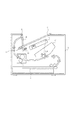
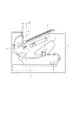
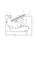
図2は、トレイカム11の短径部の外周面が排出トレイ9と当接する排出トレイ9の積載位置(破線位置)から、トレイカム11の回転により長径部の外周面が排出トレイ9と係合して矢印9aの方向に排出トレイ9が移動したときの移動位置(実線位置)を示す。
FIG. 2 shows that the outer peripheral surface of the long diameter portion engages with the discharge tray 9 by the rotation of the
トレイカム11が破線位置から実線位置に回転すると、トレイカム11の排出トレイ9と接触する外周面は、回転中心からの径が大きくなることによりトレイバネ12の押圧力に抗して排出トレイ9を規制部としての後端規制板10から離間する方向に押す。これにより、排出トレイ9を移動位置に移動させる。
When the
さらに、トレイカム11が実線位置から破線位置に回転すると、トレイカム11の排出トレイ9との接触する外周面は、回転中心からの径が小さくなることによりトレイバネ12が排出トレイ9を後端規制板10に接近させる方向に押圧する。これにより、排出トレイ9を再び積載位置に移動させる。
Further, when the
このように、シート移動手段を構成するトレイカム11、トレイバネ12の作用により、排出トレイ9は積載位置と移動位置の2つの位置を移動可能に保持される。
As described above, the discharge tray 9 is held movably between the stacking position and the moving position by the action of the
次に、排出シートが排出トレイ9上に排出される際の動作について図3ないし図5を用いて説明する。 Next, the operation when the discharge sheet is discharged onto the discharge tray 9 will be described with reference to FIGS.
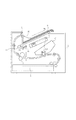
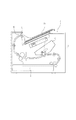
図3のように、排出ローラ対8から排出されたシートが、排出トレイ9上に正常に積載されず、排出シートのシート排出方向上流端が排出ローラ対8にもたれかかってしまう、いわゆる後端もたれが発生する場合がある。 As shown in FIG. 3, the sheet discharged from the discharge roller pair 8 is not normally stacked on the discharge tray 9, and the upstream end of the discharged sheet in the sheet discharge direction leans against the discharge roller pair 8. Leaning may occur.
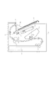
このような場合においても、トレイカム11を矢印11aの方向に回転させ、排出トレイ9を矢印9aの方向に移動させることにより、図4に示すように、排出トレイ9と既に排出トレイ9上に積載されたシートとが移動する。このように、既に排出トレイ9上に積載されたシートが、排出トレイ9が移動すると共に移動することによって、排出ローラ対8にもたれかかったシートのシート排出方向上流端が排出トレイ9上に落下する。なお、排出トレイ9上にシートが積載されていない状態であっても、上述の動作により排出ローラ対8にもたれかかったシートのシート排出方向上流端を排出トレイ9上に落下させ、排出トレイ9上への良好な積載が可能となる。
Even in such a case, the
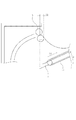
ここで、排出ローラ対8にもたれかかったシートの排出トレイ9上へ落下が可能な条件について説明する。 Here, the conditions under which the sheet leaning against the discharge roller pair 8 can drop onto the discharge tray 9 will be described.
図7において、シートの排出ローラ対8にもたれかかる位置とは、排出ローラ対8のニップ部(挟持部)よりもシート排出方向下流側になる。そのため、排出ローラ対8のニップ部から排出ローラ対8の水平方向最下流端までの距離をX1とすると、距離X1以上移動させることができれば、排出ローラ対8にもたれかかったシートを確実に排出トレイ9上に落下積載することが可能となる。 In FIG. 7, the position where the sheet leans against the discharge roller pair 8 is on the downstream side in the sheet discharge direction with respect to the nip portion (nip portion) of the discharge roller pair 8. Therefore, if the distance from the nip portion of the discharge roller pair 8 to the most downstream end in the horizontal direction of the discharge roller pair 8 is X1, the sheet leaning against the discharge roller pair 8 can be reliably discharged if the distance X1 or more can be moved. It becomes possible to drop and load on the tray 9.
排出ローラ対8にもたれかかったシートを排出トレイ9上に落下積載するために、排出トレイ9の必要な移動量X2は、排出トレイ9と水平線とのなす角度をθとすると、
X2≧X1/cosθ
となる。
In order to drop and stack the sheet leaning on the discharge roller pair 8 onto the discharge tray 9, the necessary movement amount X2 of the discharge tray 9 is defined as follows. The angle between the discharge tray 9 and the horizontal line is θ.
X2 ≧ X1 / cosθ
It becomes.
よって、トレイカム11においては、排出トレイ9を移動させる際の短径部側の回転中心から外周面までの距離をR1、長径部側の回転中心から外周面までの距離をR2とすると、
R2−R1=X2≧X1/cosθ
という関係が成立する。
Accordingly, in the
R2-R1 = X2 ≧ X1 / cos θ
The relationship is established.
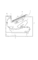
以上のような配置構成により、図4に示すように、シート排出方向上流端が排出ローラ対8にもたれかかっていたシートは、排出トレイ9上に積載可能となる。しかしながら、上述したように排出トレイ9上にシート排出方向上流端を落下させたシートは、図5に示すように、既に排出トレイ9上に整列して積載されたシートとはシート排出方向上流端の位置がずれてしまう。 With the above arrangement, as shown in FIG. 4, the sheet whose upstream end in the sheet discharge direction is leaning against the discharge roller pair 8 can be stacked on the discharge tray 9. However, as described above, the sheet whose upstream end in the sheet discharge direction is dropped on the discharge tray 9 is different from the sheet that is already stacked and stacked on the discharge tray 9 as shown in FIG. Will be misaligned.
このような場合、排出トレイ9上の積載シートに対して整合動作を行う必要がある。そこで、図5に示すトレイカム11を矢印11b方向に回転させて、排出トレイ9を矢印9bの方向に移動させる。このようにすると、後端規制板10の方向に排出トレイ9上のシートを移動させることができる。図5に示されるように、排出トレイ9上に落下したシートは、既に積載されたシートよりもシート排出方向上流端が後端規制板10側に飛び出しているため、先に後端規制板10に突き当たる。そして、排出されたシートのシート排出方向上流端を後端規制板10に当接させることにより、図6のように、排出されたシートと既積載シートのシート排出方向上流端の整合が行われる。
In such a case, it is necessary to perform an alignment operation on the stacked sheets on the discharge tray 9. Therefore, the
上述したように、排出トレイ9上のシートを後端規制板10の方向に移動させたとき、図8に示すように、排出トレイ9上に排出されたシートが後端規制板10に突き当たって座屈して折れ曲がったり、隙間に入り込んだりすることがないようにする必要がある。そのため、腰の弱い薄いシートであっても座屈しないように、排出トレイ9の移動量X2は20mm以下であることが望ましい。
As described above, when the sheet on the discharge tray 9 is moved in the direction of the rear
つまり、排出トレイ9の必要な移動量X2は、
20mm≧X2≧X1/cosθ
ということが言える。
That is, the required movement amount X2 of the discharge tray 9 is
20 mm ≧ X2 ≧ X1 / cos θ
I can say that.
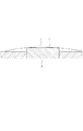
ただし、腰の弱いシートが座屈しないようにするには、排出トレイ9のシート積載面のシート排出方向と交差する幅方向に凹凸形状をつけ、排出されたシートが座屈しないように波形に腰付けすることで、移動量X2をさらに大きくすることは可能である。 However, in order to prevent buckled sheets from buckling, an uneven shape is formed in the width direction intersecting with the sheet discharge direction of the sheet stacking surface of the discharge tray 9 so that the discharged sheets are not corrugated. It is possible to further increase the movement amount X2 by sitting on the back.
図10に示すように、排出トレイ9のシート積載面のシート排出方向と交差する幅方向両端部を凹形状にして、幅方向中央部を凸形状の突出部9aとすることにより、シートを波形に腰付けした状態で排出トレイ9上に積載することができる。さらに、凸形状の突出部9aのみトレイカム11の回転により移動可能にすることで、シートを腰付けした状態で移動できるため、薄紙であっても後端規制板10に突き当たって座屈しにくくようにすることができる。
As shown in FIG. 10, the sheet is corrugated by making the width direction both ends intersecting the sheet discharge direction of the sheet stacking surface of the discharge tray 9 into a concave shape and making the central portion in the width direction into a convex protruding portion 9a. It can be loaded on the discharge tray 9 while being seated on. Furthermore, since only the projecting protrusion 9a can be moved by rotating the
上述した動作により後端規制板10にもたれたシートに関しても排出トレイ9上にシート排出方向上流端を確実に落下させて高い整列性を実現し、積載することが可能である。本実施の形態において、排出されたシートが排出ローラ対8にもたれかかるのを防止するために必要な排出トレイ9の移動量X2について説明している。しかしながら、移動量X2をさらに大きくすることによって排出ローラ対8への後端もたれのみならず、後端規制板10への後端もたれを解消することができる。特に、近年、大容量のシートが積載可能な排出トレイが要求され、排出ローラ対のニップ部と排出トレイのシート積載面との高さ、すなわち後端規制板の高さが増大する傾向にあり、後端規制板への後端もたれを解消することが整列性、積載性の向上につながる。
Even with respect to the sheet leaning against the trailing
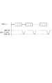
ここで、上述の一連動作の開始から終了時間について、印刷ジョブとの関係を示したタイミングを図9のタイミングチャートを用いて説明する。 Here, the timing indicating the relationship from the start to the end time of the series of operations described above with the print job will be described with reference to the timing chart of FIG.
図3ないし図5において定着装置Tから排出ローラ対8への搬送路には図示しない排出センサが設けられており、シートが搬送路を通過する際、排出センサはシートのシート排出方向下流端、若しくは上流端を検知している。これにより、排出ローラ対8のニップ部にシートのシート排出方向下流端が挟持される時間と、排出ローラ対8のニップ部からシートのシート排出方向上流端が排出される時間を予測している。 3 to 5, a discharge sensor (not shown) is provided in the conveyance path from the fixing device T to the discharge roller pair 8. When the sheet passes through the conveyance path, the discharge sensor is the downstream end of the sheet in the sheet discharge direction. Or the upstream end is detected. As a result, the time when the downstream end of the sheet in the sheet discharge direction is sandwiched between the nip portion of the discharge roller pair 8 and the time when the upstream end of the sheet in the sheet discharge direction is discharged from the nip portion of the discharge roller pair 8 are predicted. .
先行シート(図9の印刷ジョブ1ページ)のシート排出方向上流端が、排出ローラ対8のニップ部より排出され、排出ローラ対8に後端もたれした状態で排出トレイ9上に積載される。この排出トレイ9上に積載された先行シートが排出ローラ対8のニップ部を通過後であれば、排出トレイ9を移動することにより先行シートは排出トレイ9と一緒に移動可能である。そこで排出トレイ9は、積載位置からの移動を開始する。 The upstream end of the preceding sheet (one page of the print job in FIG. 9) in the sheet discharge direction is discharged from the nip portion of the discharge roller pair 8 and is stacked on the discharge tray 9 with the rear end leaning on the discharge roller pair 8. If the preceding sheet stacked on the discharge tray 9 has passed through the nip portion of the discharge roller pair 8, the preceding sheet can be moved together with the discharge tray 9 by moving the discharge tray 9. Therefore, the discharge tray 9 starts to move from the loading position.
そして、後続シート(図9の印刷ジョブ2ページ)のシート排出方向下流端が排出トレイ9上に積載された先行シートの上面に接触する前までに、排出トレイ9は移動位置まで移動する動作と、さらに移動位置から積載位置まで戻る動作を完了する。 The discharge tray 9 moves to the moving position before the downstream end of the subsequent sheet (page 2 of the print job in FIG. 9) contacts the upper surface of the preceding sheet stacked on the discharge tray 9. Further, the operation of returning from the moving position to the loading position is completed.
この完了のタイミングは、排出ローラ対8から排出される後続シートのシート排出方向下流端と排出トレイ9上に積載された先行シートの上面とが接触した際の摩擦により、先行シートが排出トレイ9と一緒に積載位置へ戻るのを妨げられないようにするためである。つまり、後続シート(図9の印刷ジョブ2ページ)のシート排出方向下流端が排出ローラ対8のニップ部を通過して排出トレイ9上に積載された先行シートの上面に接触する前までに完了していればよい。 The completion timing is determined by the friction when the downstream end of the subsequent sheet discharged from the discharge roller pair 8 comes into contact with the upper surface of the preceding sheet stacked on the discharge tray 9. This is so that it is not obstructed to return to the loading position together. That is, it is completed before the downstream end of the succeeding sheet (page 2 of the print job in FIG. 9) passes through the nip portion of the discharge roller pair 8 and contacts the upper surface of the preceding sheet stacked on the discharge tray 9. If you do.
上述した一連の動作により、後端もたれの発生を防止し、整列性と積載性を両立した良好な排出積載が可能となる。 By the series of operations described above, it is possible to prevent the occurrence of back end leaning and to perform excellent discharge stacking that achieves both alignment and stackability.
ところで、排出トレイ9上に後端もたれ検知手段を設ければ、上述のように後端もたれを解消するための一連の動作は後端もたれが発生したときのみ行えばよく、余分な動作を省くことが可能となる。 By the way, if the trailing edge lean detection means is provided on the discharge tray 9, the series of operations for eliminating the trailing edge leaning may be performed only when the trailing edge leaning occurs as described above, and unnecessary operations are omitted. It becomes possible.
次に本発明の第2の実施の形態を添付図面に基づいて説明する。 Next, a second embodiment of the present invention will be described with reference to the accompanying drawings.
レーザビームプリンタの主な構成(スキャナーS、プロセスカートリッジC、定着装置T等)、画像形成プロセスに関わる点については、前述した実施の形態1と同様であるので省略する。 Since the main configuration of the laser beam printer (scanner S, process cartridge C, fixing device T, etc.) and the points related to the image forming process are the same as those in the first embodiment, description thereof will be omitted.
続いて、本実施の形態における構成の特徴を述べる。 Next, features of the configuration in the present embodiment will be described.
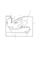
図11において、定着装置Tのシート排出方向下流の排出ローラ対8から排出されたシートを積載する排出トレイ9には、無端ベルト部材からなるシート移動手段としてのトレイベルト13が排出トレイ9のシート積載面よりも突出するように設けられている。また、トレイベルト13の上面は、排出シートを積載して移動することができるようにしており、図示しないモータ等の駆動源からの正逆回転の切り替えによって矢印13a、または矢印13bの方向に移動する。
In FIG. 11, a
矢印13aは後端規制板10から離れる方向であり、本実施の形態においては、排出トレイ9のシート積載面と略平行に、かつ、排出方向と一致する方向である。矢印13bは後端規制板10に近づく方向であり、本実施の形態においては、排出トレイ9のシート積載面と略平行に、かつ、排出方向と逆方向であることを示している。
An
次に、シートが排出トレイ9上に排出される際の動作について説明する。 Next, an operation when a sheet is discharged onto the discharge tray 9 will be described.
図12のように排出ローラ対8から排出トレイ9上に整列して積載されず、シート排出方向上流端が排出ローラ対8にもたれかかるシートがある。 As shown in FIG. 12, there are sheets that are not stacked and stacked on the discharge tray 9 from the discharge roller pair 8 and the upstream end in the sheet discharge direction leans against the discharge roller pair 8.
このようなシートにおいても、トレイベルト13を回転移動させ、トレイベルト13の上面が矢印13aの方向に移動することで、図13のように既に排出トレイ9上に積載されたシートが移動する。すると、排出ローラ対8に後端もたれしたシートのシート排出方向下流端側の既に排出トレイ9上に積載された部分が、トレイベルト13が移動すると共に移動することによって、排出ローラ対8にもたれたシートのシート排出方向上流端が排出トレイ9上に落下する。
Even in such a sheet, by rotating the
ここで、シートの排出トレイ9上への落下が可能な条件について図16を用いて説明する。 Here, the conditions under which the sheet can drop onto the discharge tray 9 will be described with reference to FIG.
シートの排出ローラ対8に後端もたれする位置とは、排出ローラ対8のニップ部よりもシート排出方向下流側になる。そのため、排出ローラ対8のニップ部から排出ローラ対8の水平方向最下流位置までの距離をX1とすると、距離X1以上移動させることができれば、排出ローラ対8にもたれかかったシートを確実に排出トレイ9上に落下させることが可能となる。 The position where the trailing edge of the sheet discharge roller pair 8 leans is downstream of the nip portion of the discharge roller pair 8 in the sheet discharge direction. Therefore, if the distance from the nip portion of the discharge roller pair 8 to the most downstream position in the horizontal direction of the discharge roller pair 8 is X1, the sheet leaning against the discharge roller pair 8 is surely discharged if the distance X1 or more can be moved. It can be dropped on the tray 9.
そのために、本実施の形態におけるトレイベルト13の、排出ローラ対8にもたれかかったシートを排出トレイ9上に落下積載するために必要な移動量X2は、排出トレイ9と水平線とのなす角度をθとすると、
X2≧X1/cosθ
という関係が成立する。
Therefore, the movement amount X2 of the
X2 ≧ X1 / cosθ
The relationship is established.
よって、図14のように、シート排出方向上流端が排出ローラ対8にもたれていたシートも、排出トレイ9上に積載可能となる。しかしながら、排出トレイ9上に排出されたシートは、既に排出トレイ9上に積載されたシートとはシート排出方向にずれてしまう可能性がある。 Therefore, as shown in FIG. 14, the sheet whose upstream end in the sheet discharge direction is leaned against the discharge roller pair 8 can be stacked on the discharge tray 9. However, the sheet discharged onto the discharge tray 9 may be shifted in the sheet discharge direction from the sheets already stacked on the discharge tray 9.
このような場合、排出トレイ9上の積載シートに対して整合動作を行う必要がある。そこで、トレイベルト13を矢印13bの方向に回転移動すると、後端規制板10に向かって排出トレイ9上のシートを移動させることができる。排出トレイ9上に排出されたシートシート排出方向上流端は、図14で示すように、既に積載されたシートのシート排出方向上流端よりも後端規制板10側に飛び出しているため、先に後端規制板10に突き当たる。そして、排出されたシートのシート排出方向上流端を後端規制板10に当接させることにより、図15に示されるように、排出されたシートと既積載シートのシート排出方向上流端の整合が行われる。
In such a case, it is necessary to perform an alignment operation on the stacked sheets on the discharge tray 9. Therefore, when the
上述した排出トレイ9の一連の移動動作により、後端もたれを解消し、良好な整列性と積載性を両立した排紙積載が可能となる。 The series of moving operations of the discharge tray 9 described above eliminates back end leaning and enables discharge stacking that achieves both good alignment and stackability.
なお、上述した排出トレイ9の一連の移動動作の開始から終了は、実施の形態1の説明と同様であるため省略する。 Note that the start and end of the series of movement operations of the discharge tray 9 described above are the same as those described in the first embodiment, and thus are omitted.
また、実施の形態1と同様に、排出トレイ上に排出されたシートの後端もたれ検知手段を設ければ、上述のような排出トレイ9の一連の移動動作は後端残りしたときのみ行えばよく、余分な動作を省くことが可能となる。 Further, as in the first embodiment, if a trailing edge leaning detection unit is provided on the discharge tray, the above-described series of movement operations of the discharge tray 9 can be performed only when the trailing edge remains. Well, it is possible to omit extra operations.
上述した実施の形態において、本願発明に係るシート積載装置を画像形成装置に一体的に組み込んだ構成について説明したが、本願発明に係るシート積載装置を画像形成装置とは別装置、例えば、フィニッシャ等のシート処理装置に適用しても本願発明は有効である。 In the embodiment described above, the configuration in which the sheet stacking apparatus according to the present invention is integrated into the image forming apparatus has been described. However, the sheet stacking apparatus according to the present invention is different from the image forming apparatus, such as a finisher. The present invention is effective even when applied to the sheet processing apparatus.
A 装置本体
C プロセスカートリッジ
Cd 電子写真感光ドラム
S スキャナー
T 定着装置
8 排出ローラ
9 排出トレイ
10 後端規制板
11 トレイカム
12 トレイバネ
13 トレイベルト
A device main body C process cartridge Cd electrophotographic photosensitive drum S scanner T fixing device 8 discharge roller 9
Claims (9)
前記排出部により排出されたシートを積載するシート積載部と、
前記シート積載部に積載されたシートのシート排出方向上流端を規制する規制部と、
前記シート積載部に積載されたシートを前記規制部に対して離間、接近する方向に移動させるシート移動手段と、を備え、
前記シート移動手段は、前記シート積載部に排出されたシートを前記規制部に対して離間する方向に移動させた後、前記規制部に対して接近する方向に移動させることを特徴とするシート積載装置。 A discharge unit for discharging the sheet;
A sheet stacking unit for stacking sheets discharged by the discharge unit;
A regulation unit that regulates an upstream end in the sheet discharge direction of the sheets stacked on the sheet stacking unit;
Sheet moving means for moving the sheets stacked on the sheet stacking unit in a direction of separating and approaching the regulating unit,
The sheet moving means moves the sheet discharged to the sheet stacking portion in a direction away from the restricting portion, and then moves the sheet in a direction approaching the restricting portion. apparatus.
画像形成されたシートを積載する請求項1ないし8のいずれか1項に記載のシート積載装置と、を備えたことを特徴とする画像形成装置。 Image forming means for forming an image on a sheet;
9. An image forming apparatus comprising: the sheet stacking apparatus according to claim 1 for stacking sheets on which images are formed.
Priority Applications (1)
| Application Number | Priority Date | Filing Date | Title |
|---|---|---|---|
| JP2008320303A JP2010143668A (en) | 2008-12-16 | 2008-12-16 | Sheet stacking device and image forming device |
Applications Claiming Priority (1)
| Application Number | Priority Date | Filing Date | Title |
|---|---|---|---|
| JP2008320303A JP2010143668A (en) | 2008-12-16 | 2008-12-16 | Sheet stacking device and image forming device |
Publications (1)
| Publication Number | Publication Date |
|---|---|
| JP2010143668A true JP2010143668A (en) | 2010-07-01 |
Family
ID=42564502
Family Applications (1)
| Application Number | Title | Priority Date | Filing Date |
|---|---|---|---|
| JP2008320303A Pending JP2010143668A (en) | 2008-12-16 | 2008-12-16 | Sheet stacking device and image forming device |
Country Status (1)
| Country | Link |
|---|---|
| JP (1) | JP2010143668A (en) |
-
2008
- 2008-12-16 JP JP2008320303A patent/JP2010143668A/en active Pending
Similar Documents
| Publication | Publication Date | Title |
|---|---|---|
| JP5393246B2 (en) | Sheet stacking apparatus and image forming apparatus | |
| JP5488559B2 (en) | Sheet post-processing apparatus and sheet folding method | |
| JP7838065B2 (en) | Image reading device and image forming device | |
| JP6957203B2 (en) | Sheet transfer device and image forming device | |
| JP7551861B2 (en) | Image forming device | |
| CN100381946C (en) | Sheet discharging apparatus and sheet treating apparatus provided with the same | |
| US10315878B2 (en) | Sheet conveying device, sheet discharging device incorporating the sheet conveying device and image forming apparatus incorporating the sheet conveying device and the sheet discharging device | |
| JP6428674B2 (en) | Sheet conveying apparatus and image forming apparatus having the same | |
| JP6622473B2 (en) | Sheet detecting apparatus and image forming apparatus | |
| JPH10218432A (en) | Paper sheet carrying device | |
| JP2003155130A (en) | Image forming device | |
| KR101286885B1 (en) | Cassette containing recording medium and imaging forming apparatus having the same | |
| JPH10218503A (en) | Document feeder | |
| JP7537122B2 (en) | SHEET DISCHARGE DEVICE, DOCUMENT CONVEYING DEVICE, AND IMAGE FORMING APPARATUS EQUIPPED WITH SAME | |
| JP2004307107A (en) | Paper tray, and automatic paper feeder and image forming apparatus including the same | |
| JP2010143668A (en) | Sheet stacking device and image forming device | |
| JP2012180184A (en) | Sheet stacking device, sheet feeding device, and image forming device | |
| JP2017206383A (en) | Sheet detection device and image formation apparatus | |
| JP2018002377A (en) | Sheet material storage device, sheet material conveyance device and image forming apparatus | |
| JP6384450B2 (en) | Sheet stacking apparatus, sheet post-processing apparatus including the same, and image forming apparatus | |
| JP4423217B2 (en) | Sheet discharging apparatus and sheet processing apparatus having the same | |
| JP4712680B2 (en) | Feeding device, image forming device | |
| JP4027260B2 (en) | Paper discharge device, image forming device | |
| JP2007217156A (en) | Sheet delivery mechanism and image forming device equipped with it | |
| JP4037296B2 (en) | Document feeder |
Legal Events
| Date | Code | Title | Description |
|---|---|---|---|
| RD01 | Notification of change of attorney |
Free format text: JAPANESE INTERMEDIATE CODE: A7421 Effective date: 20100630 |