JP2010143680A - Carrying device - Google Patents
Carrying device Download PDFInfo
- Publication number
- JP2010143680A JP2010143680A JP2008321009A JP2008321009A JP2010143680A JP 2010143680 A JP2010143680 A JP 2010143680A JP 2008321009 A JP2008321009 A JP 2008321009A JP 2008321009 A JP2008321009 A JP 2008321009A JP 2010143680 A JP2010143680 A JP 2010143680A
- Authority
- JP
- Japan
- Prior art keywords
- roller
- conveyor belt
- forklift
- rotating roller
- carrying
- Prior art date
- Legal status (The legal status is an assumption and is not a legal conclusion. Google has not performed a legal analysis and makes no representation as to the accuracy of the status listed.)
- Pending
Links
- 238000004519 manufacturing process Methods 0.000 abstract description 6
- 230000032258 transport Effects 0.000 description 20
- 238000011144 upstream manufacturing Methods 0.000 description 5
- 238000009434 installation Methods 0.000 description 3
- 230000000694 effects Effects 0.000 description 2
- 230000002441 reversible effect Effects 0.000 description 2
- 238000013459 approach Methods 0.000 description 1
Images
Landscapes
- Relays Between Conveyors (AREA)
- Rollers For Roller Conveyors For Transfer (AREA)
Abstract
Description
この発明は、ベルトコンベアを用いた搬送装置に係り、詳細には、他の駆動手段により駆動させる搬送装置に関する。 The present invention relates to a transport device using a belt conveyor, and more particularly, to a transport device driven by other driving means.
自動車工場などの製造工場では、製品を搬送するために製品搬送用の搬送装置を使用している。
この搬送装置では、製造された製品を搬送する際に、先に製造された製品から搬送し先に取り出せる事が望まれるので、製品を先入れしたものから先に取出せる所謂先入れ先出し可能な搬送装置が用いられている。
In a manufacturing factory such as an automobile factory, a product conveying device is used to convey a product.
In this transport device, when transporting a manufactured product, it is desired that the product manufactured first can be transported and taken out to the destination. Is used.
先入れ先出し搬送装置では、通常ベルトコンベヤなどの搬送手段を備えている。
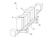
即ち、図3に表すように、搬送装置100は、ベルトコンベヤ101を駆動モータ102及び駆動モータ103によって駆動させ、ベルトコンベヤ101の上流から下流へ流れてきたものを順次フォークリフトで取出していた。
従って、ベルトコンベヤ101を駆動させるための駆動手段となる駆動モータ102及び駆動モータ103は必須であり、駆動モータ102及び駆動モータ103を駆動させる電源を搬送装置100までの敷設等の作業も必須である。
The first-in first-out transport apparatus is usually provided with transport means such as a belt conveyor.
That is, as shown in FIG. 3, the
Therefore, the
しかしながら、搬送装置100を低予算で作成し、製品の原価への転嫁を極力抑えて製品価格を抑えたいという目的を達成するためには、更に搬送装置100の低価格製造が求められ、現状では、ベルトコンベヤ101及びこれを駆動させるための駆動手段である駆動モータ102及び駆動モータ103が必須であるため、搬送装置100を低価格で製造することは困難であるという問題点を有した。
また、ベルトコンベヤ101の駆動に駆動モータ102及び駆動モータ103が必須であり、これに伴い電源の設置も必須となるので、搬送装置100の設置場所を必要に応じ頻繁に変更することが困難であるという問題点を有した。
However, in order to achieve the purpose of creating the
In addition, since the
この発明は、上記問題点に鑑み、更なる低価格で構成可能な搬送装置を提供することを目的とする。 In view of the above problems, an object of the present invention is to provide a transport apparatus that can be configured at a lower price.
そこでこの発明は、搬送装置の構成を更に簡略化して低価格とすべく、 In view of this, the present invention further simplifies the configuration of the conveying device and reduces the cost.
両端に設けるローラ間に架け渡されるコンベヤベルトによって被搬送物を搬送可能であり、少なくともコンベヤベルトの下流側端は、被搬送物を載置しコンベヤベルトから離脱搬出可能な搬出装置の被搬送物載置部を位置可能に形成してなり、コンベヤベルトの下流側端に設けローラを駆動可能であって被搬送物を搬送方向へ回転可能であると共に逆転不可能な一方向回転ローラをコンベヤベルト端部の外側へ配置させ、且つ、一方向回転ローラと適宜間隔を持って補助ローラを設置させ、一方向回転ローラと補助ローラとの間にタイヤ駆動により製品搬出可能な搬出装置のタイヤを乗せ上げて一方向回転ローラを回転させることを特徴とする搬送装置、 The object to be conveyed can be conveyed by a conveyor belt spanned between rollers provided at both ends, and at least the downstream end of the conveyor belt can carry the object to be conveyed, and can be unloaded from the conveyor belt. A mounting portion is formed so as to be positionable, and a roller provided at the downstream end of the conveyor belt can be driven to rotate a conveyed object in the conveying direction and cannot be reversed. Auxiliary rollers are placed outside the end and at an appropriate distance from the unidirectional rotating roller, and the tire of the unloading device that can carry out the product by driving the tire is placed between the unidirectional rotating roller and the auxiliary roller. A conveying device characterized by raising and rotating a one-way rotating roller;
を提供する。これによれば、被搬送物が載置されたコンベヤベルトは、一方向回転ローラと補助ローラとの間に位置された搬出装置、例えばフォークリフトの前輪タイヤを回転させると回転されて被搬送物を、コンベヤベルトの反フォークリフト側からフォークリフト側へと搬送することとなる。フォークリフト作業者は、被搬送物が被搬送物載置部であるフォークリフトのフォーク上に位置したことを確認して一方向回転ローラの回転を完了させる。従って、前輪駆動であるフォークリフトの前輪が一方向回転ローラと補助ローラとの間に位置するように前進して接近し、そのままの前輪回転方向で一方向回転ローラを回転させることとなる。
そして、フォークリフト作業者は、フォークリフトを一方向回転ローラと補助ローラとの間から離脱させるべく逆転させる。すると、フォークリフトはコンベヤベルトの端部から遠ざかる方向へ移動しようとし、この時一方向回転ローラは逆転不可能であるので、コンベヤベルトを駆動させず、フォークリフトが一方向回転ローラと補助ローラとの間から離脱可能となる。
そして、この発明では、前記補助ローラの構成を、
I will provide a. According to this, the conveyor belt on which the object to be conveyed is placed is rotated by rotating a carry-out device positioned between the one-way rotating roller and the auxiliary roller, for example, a front wheel tire of a forklift. Then, the conveyor belt is transported from the anti-forklift side to the forklift side. The forklift operator confirms that the object to be conveyed is positioned on the fork of the forklift that is the object to be conveyed, and completes the rotation of the one-way rotating roller. Therefore, the front wheel of the forklift that is front wheel drive moves forward and approaches so as to be positioned between the one-way rotation roller and the auxiliary roller, and the one-way rotation roller is rotated in the same front wheel rotation direction.
Then, the forklift operator reverses the forklift so as to separate it from between the one-way rotating roller and the auxiliary roller. Then, the forklift tries to move away from the end of the conveyor belt. At this time, since the one-way rotating roller cannot be reversed, the forklift does not drive the forklift between the one-way rotating roller and the auxiliary roller. It is possible to leave.
And in this invention, the configuration of the auxiliary roller is
一方向回転ローラと同方向へのみ回転可能であり逆転不可能な一方向回転ローラ、 A unidirectional rotating roller that can rotate only in the same direction as the unidirectional rotating roller and cannot be reversed.
で構成し、一方向回転ローラと補助ローラとの間に位置して駆動させるタイヤの回転が一方向、即ち、フォークリフトが前進して搬送装置の端部外方に設ける一方向回転ローラと補助ローラとの間に進入する側の回転では、一方向回転ローラと補助ローラとはタイヤの駆動力により回転させられ、フォークリフトが一方向回転ローラと補助ローラとの間から離脱する方向への回転では、一方向回転ローラと補助ローラとは逆転不可能なため回転しないのでフォークリフトは一方向回転ローラと補助ローラとの間から容易に離脱する。 The one-way rotating roller and the auxiliary roller provided between the one-way rotating roller and the auxiliary roller are driven in one direction, that is, the forklift is moved forward and outside the end of the conveying device. , The one-way rotating roller and the auxiliary roller are rotated by the driving force of the tire, and the forklift is rotated in the direction of separating from the one-way rotating roller and the auxiliary roller, Since the one-way rotating roller and the auxiliary roller cannot rotate in reverse, the forklift is easily separated from between the one-way rotating roller and the auxiliary roller.
上記のように構成する搬送装置では、駆動部を必要とせず搬出装置の駆動手段によって駆動可能に構成するので、搬送装置の製造コストを押さえることが可能となり、低価格で搬送装置を製造できるという効果を有する。
更に、駆動部を必要としないので、電源の供給が必要なく、設置場所を容易に変更可能であるという効果を有する。
In the transport apparatus configured as described above, since it is configured to be able to be driven by the drive means of the carry-out apparatus without the need for a driving unit, it is possible to reduce the manufacturing cost of the transport apparatus and to manufacture the transport apparatus at a low price. Has an effect.
Furthermore, since no drive unit is required, there is an effect that it is not necessary to supply power and the installation location can be easily changed.
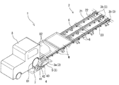
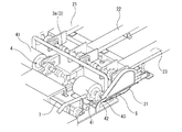
以下に、この発明の実施例を、図面に基づき説明する。図1はこの発明の実施例を表す斜視説明図であり、図2は図1に表す実施例の一部を拡大した一部拡大斜視説明図である。 Embodiments of the present invention will be described below with reference to the drawings. FIG. 1 is a perspective explanatory view showing an embodiment of the present invention, and FIG. 2 is a partially enlarged perspective explanatory view in which a part of the embodiment shown in FIG. 1 is enlarged.
1はこの発明にかかる搬送装置である。搬送装置1は、所謂先入れ先出しを可能とする搬送装置である。搬送装置1は、被搬送物Wを搬送可能なコンベヤベルト2と、コンベヤベルト2の両端に位置してコンベヤベルト2が架け渡されるローラ3と、両端のローラ3の間でコンベヤベルト2を支持するローラ6とを有する。更に搬送装置1には、コンベヤベルト2の一方の端部でコンベヤベルト2の外方に位置され、該端部に設けた端部ローラ3との間に駆動チェーン5を架け渡して端部ローラ3を駆動可能な一方向回転ローラ4を設ける。
Reference numeral 1 denotes a conveying apparatus according to the present invention. The transport apparatus 1 is a transport apparatus that enables so-called first-in first-out. The conveyance device 1 supports the
そして、一方向回転ローラ4のコンベヤベルト2と反対側に適宜間隔を置いて補助ローラ7を設置する。一方向回転ローラ4と補助ローラ7との間隔は、搬出装置であるフォークリフト8のタイヤ81が両ローラ4,7に乗り上げ、両ローラ4,7をタイヤ81が駆動可能な間隔を空けている。また、補助ローラ7は一方向回転ローラ4より径小に形成し、タイヤ81の駆動力を一方向回転ローラ4に伝えやすくしている。
Then,
コンベヤベルト2は、この実施例では、3本のベルトから構成し、中間のベルト22と両端のベルト21、23との間に、一方向回転ローラ4を備える側の端部からフォークリフト8のフォーク82が進入して少なくとも各ベルト21乃至23上面より下方に位置可能に設置されている。尚、この実施例ではコンベヤベルト2を3本で構成したが、特に3本である必要はなく、2本あるいは4本以上のベルトから構成してもよく、適宜選択すれば足りる。尚、フォークリフト8はこの発明に用いられる搬出装置であり、フォークリフト8に備える上下動可能なフォーク82は被搬送物載置部であり、フォークリフト8の前輪タイヤ81はこの発明に用いられる搬出装置のタイヤである。
In this embodiment, the
コンベヤベルト2の各ベルト21は、コンベヤベルト2の両端に位置する端部ローラ3a、3b間に架け渡される。端部ローラ3a、3bは、コンベヤベルト2による製品搬入側である上流側では、各ベルト21乃至23それぞれに独立したローラ3bを設け、製品搬出側となる下流側では、各ベルト21乃至23を一方向回転ローラ4により一度に駆動可能なように全てのベルト21乃至23に亙り端部ローラ3aが設置される。
また、下流側に設ける端部ローラ3aの端部には、一方向回転ローラ4により駆動されるようにチェーン5を架け渡せるスプロケット31を備える。
Each
A
一方向回転ローラ4は、フォークリフト8のフォーク82がコンベヤベルト2の各ベルト21乃至23間に位置したときに前輪タイヤ81の位置へ、前輪タイヤ81の駆動力を伝達可能であり伝達時に前輪タイヤ81が乗り上げない程度の径を有する当接ローラ部41を備える。そして、この当接ローラ部41は、軸42によって連結され、端部ローラ3aに設けたスプロケット31と対向する位置にやはり駆動スプロケット43を固定する。
そして、駆動スプロケット43とスプロケット31との間に駆動チェーン5を架け渡すことで、駆動スプロケット43を経由して一方向回転ローラ4から伝達される回転力を端部ローラ3aへと伝達可能に形成する。
The one-way rotating
Then, the drive chain 5 is bridged between the
一方向回転ローラ4は、軸支持部等に一方向のみに回転可能な機構を有しており、フォークリフト8が前進する方向へタイヤ81を回転させる方向へ回転可能であり、その逆の方向へは回転不可能である。そして、一方向回転ローラ4の回転駆動力は、端部ローラ3aを回転させることとなるが、これによる端部ローラ3aの回転方向は被搬送物Wを上流側から下流側(フォークリフト側)へと搬送させる方向となるように端部ローラ3aも設置される。
The one-way rotating
尚、この実施例では、一方向回転ローラ4と端部ローラ3aとをチェーン及びスプロケットによって接続して駆動力を伝達可能に形成したが、両ローラにプーリを備え、該プーリの間をベルトで架け渡すように形成してもよい。また、該スプロケット間に更に歯車を設置し歯車による動力の伝達が可能に形成しても良く、適宜選択すれば足りる。
また、一方向回転ローラ4に備える一方向にのみ回転できるという機構も、一方向回転ローラ4の本体に有せず、例えば前記歯車機構による駆動力の伝達などでは、両ローラに設ける歯車との間に設置する歯車にこのような機構(例えばラチェット機構のようなもの)を備えさせても良く、この場合、この発明においては一方向にのみに回転可能な該機構を含めて一方向回転ローラ4という。
In this embodiment, the one-way rotating
In addition, the mechanism that can rotate only in one direction provided in the one-way
ローラ6は、従来のベルトコンベヤ装置である搬送装置1に備えるものと何ら変更は内ので、詳説は省略する。
The
補助ローラ7は、前記した通り、一方向回転ローラ4との間にフォークリフト8の前輪タイヤ81が乗り上げられる間隔を持って設置される。そして、補助ローラ7は、一方向回転ローラ4同様に、一方向にのみ回転可能な機構を備え、一方向回転ローラ4が回転可能な方向に前輪タイヤ81が回転したときにやはり回転可能であり、その逆方向へは回転不可能である。尚、補助ローラ7は、この一方向にのみ回転可能とさせる機構の設置は必須ではなく、フリーローラとしても良いが、該機構を備えた方が、フォークリフト8がスムーズに離脱可能となる。
As described above, the
このように構成する搬送装置1の端部ローラ3a側へ作業者がフォークリフト8のフォーク82を各ベルト21乃至23間に位置させるようにフォークリフト8を操作し、フォークリフト8の前輪タイヤ81を一方向回転ローラ4及び補助ローラ7の間に乗り上げさせる。そして前輪タイヤ81を駆動させると、一方向回転ローラ4及び補助ローラ7は回転され、一方向回転ローラ4の回転がチェーン5により端部ローラ3aへと伝達される。
The operator operates the
するとコンベヤベルト2は、上流側に載置されている被搬送物Wを下流側へと搬送する。
やがて、被搬送物Wがフォークリフト8のフォーク82上へ位置された所で作業者がフォークリフト8の前輪タイヤ81の駆動を停止させてフォーク82を上方へ移動させてベルト2から浮き上がらせて支持する。
この状態でフォークリフト8の前輪タイヤ81を逆転させてフォークリフト8がコンベヤベルト2から遠ざかる方向へ移動するように駆動させると、一方向回転ローラ4及び補助ローラ7は逆転不可能なので回転せず、前輪タイヤ81は補助ローラ7を乗り上げて搬送装置1から離脱する。
Then, the
Eventually, when the article to be conveyed W is positioned on the
In this state, when the
この発明は、製品を搬送する搬送装置から製品を搬出するための搬出手段が駆動力を有している場合の搬送装置に用いることができ、フォークリフトによる搬出が行われる自動車工場などの搬送装置に適用可能である。 The present invention can be used in a transport device in the case where the unloading means for unloading the product from the transport device that transports the product has a driving force, and is used in a transport device such as an automobile factory where unloading is performed by a forklift. Applicable.
1 搬送装置
2 コンベヤベルト
21 ベルト
22 中央のベルト
23 ベルト
3 端部ローラ
3a 下流側(駆動側)端部ローラ
3b 上流側端部ローラ
31 スプロケット
4 一方向回転ローラ
41 当接ローラ部
42 軸
43 駆動スプロケット
5 駆動ベルト
6 ローラ
7 補助ローラ
8 搬出手段であるフォークリフト
81 前輪タイヤ
82 フォーク
DESCRIPTION OF SYMBOLS 1 Conveying
Claims (2)
Priority Applications (1)
| Application Number | Priority Date | Filing Date | Title |
|---|---|---|---|
| JP2008321009A JP2010143680A (en) | 2008-12-17 | 2008-12-17 | Carrying device |
Applications Claiming Priority (1)
| Application Number | Priority Date | Filing Date | Title |
|---|---|---|---|
| JP2008321009A JP2010143680A (en) | 2008-12-17 | 2008-12-17 | Carrying device |
Publications (1)
| Publication Number | Publication Date |
|---|---|
| JP2010143680A true JP2010143680A (en) | 2010-07-01 |
Family
ID=42564513
Family Applications (1)
| Application Number | Title | Priority Date | Filing Date |
|---|---|---|---|
| JP2008321009A Pending JP2010143680A (en) | 2008-12-17 | 2008-12-17 | Carrying device |
Country Status (1)
| Country | Link |
|---|---|
| JP (1) | JP2010143680A (en) |
Cited By (1)
| Publication number | Priority date | Publication date | Assignee | Title |
|---|---|---|---|---|
| KR102067753B1 (en) * | 2018-08-21 | 2020-02-21 | (주)에스티아이 | Automatic transfer apparatus of chemical container and the method thereof |
Citations (2)
| Publication number | Priority date | Publication date | Assignee | Title |
|---|---|---|---|---|
| JPS58187514U (en) * | 1982-06-09 | 1983-12-13 | 株式会社日立製作所 | conveyor equipment |
| JPS603154U (en) * | 1983-06-22 | 1985-01-11 | 南飛工業株式会社 | Mud removal and discharge equipment |
-
2008
- 2008-12-17 JP JP2008321009A patent/JP2010143680A/en active Pending
Patent Citations (2)
| Publication number | Priority date | Publication date | Assignee | Title |
|---|---|---|---|---|
| JPS58187514U (en) * | 1982-06-09 | 1983-12-13 | 株式会社日立製作所 | conveyor equipment |
| JPS603154U (en) * | 1983-06-22 | 1985-01-11 | 南飛工業株式会社 | Mud removal and discharge equipment |
Cited By (3)
| Publication number | Priority date | Publication date | Assignee | Title |
|---|---|---|---|---|
| KR102067753B1 (en) * | 2018-08-21 | 2020-02-21 | (주)에스티아이 | Automatic transfer apparatus of chemical container and the method thereof |
| WO2020040365A1 (en) * | 2018-08-21 | 2020-02-27 | (주)에스티아이 | Device and method for automatically transferring chemical container |
| CN112512939A (en) * | 2018-08-21 | 2021-03-16 | 系统科技公司 | Automatic chemical container conveying device and automatic chemical container conveying method |
Similar Documents
| Publication | Publication Date | Title |
|---|---|---|
| WO2009057450A1 (en) | Conveyance assisting device of glass ribbon | |
| CN1861499B (en) | Chain-type conveyor system | |
| CN105658551B (en) | Conveying device | |
| JP2005350147A (en) | Free-flow transport system | |
| CN101323390A (en) | Roller conveyor and conveying control method | |
| JP3185447U (en) | Conveyor equipment | |
| US20080236998A1 (en) | Conveyor with accumulating slip rolls | |
| CN210126897U (en) | Stopper for conveying device and conveying device applying same | |
| TWI272236B (en) | Conveyor of sheet body | |
| KR20120114113A (en) | Roller-chain conveyor | |
| CN106542291A (en) | Cycloconveyor belt streamline | |
| JP2005053662A (en) | Direction changing device for article | |
| KR101411845B1 (en) | Belt conveyor | |
| JP5754923B2 (en) | Rotating transfer device | |
| JP2005138918A (en) | Conveyor device | |
| JP2003191919A5 (en) | ||
| JP2002370814A (en) | Transfer device | |
| KR20080002524A (en) | Reversal method using inverter driven by Kenvey method | |
| JP2009184422A (en) | Unmanned conveying truck | |
| JP2003040430A (en) | Transport system | |
| CN213212136U (en) | Wafer conveying system | |
| KR20080083503A (en) | Spiral conveyor | |
| CN205312697U (en) | Carousel formula transition conveyer | |
| JP5983448B2 (en) | Work transfer device | |
| CN110294261A (en) | A kind of guide transport lorry |
Legal Events
| Date | Code | Title | Description |
|---|---|---|---|
| A621 | Written request for application examination |
Free format text: JAPANESE INTERMEDIATE CODE: A621 Effective date: 20111202 |
|
| A711 | Notification of change in applicant |
Effective date: 20120720 Free format text: JAPANESE INTERMEDIATE CODE: A712 |
|
| A521 | Written amendment |
Effective date: 20120822 Free format text: JAPANESE INTERMEDIATE CODE: A523 |
|
| A02 | Decision of refusal |
Effective date: 20131008 Free format text: JAPANESE INTERMEDIATE CODE: A02 |