JP2010144517A - Hermetic compressor - Google Patents
Hermetic compressor Download PDFInfo
- Publication number
- JP2010144517A JP2010144517A JP2008319128A JP2008319128A JP2010144517A JP 2010144517 A JP2010144517 A JP 2010144517A JP 2008319128 A JP2008319128 A JP 2008319128A JP 2008319128 A JP2008319128 A JP 2008319128A JP 2010144517 A JP2010144517 A JP 2010144517A
- Authority
- JP
- Japan
- Prior art keywords
- balance weight
- center
- rotation
- rotor
- drive shaft
- Prior art date
- Legal status (The legal status is an assumption and is not a legal conclusion. Google has not performed a legal analysis and makes no representation as to the accuracy of the status listed.)
- Granted
Links
Images


Landscapes
- Compressor (AREA)
- Applications Or Details Of Rotary Compressors (AREA)
- Gears, Cams (AREA)
Abstract
【課題】バランスウェイトの軌道を規制することで無用な振動を抑制し、さらに重心移動の制御性を高めることができる密閉型圧縮機を得る。
【解決手段】密閉型圧縮機100は、回転子5の下端にガイド機構10を介して取り付けられたバランスウェイト7と、駆動軸軸受4の外周の一部に設置された楕円型のカム機構8と、バランスウェイト7をカム機構8のカム面8aに押し付けるバネ9とを有し、回転子5の回転角に応じて、バランスウェイト7の重心位置を変更可能にすることによって、圧縮機構偏心部2に生じる回転トルクの変動を抑制する。
【選択図】図2The present invention provides a hermetic compressor capable of suppressing unnecessary vibrations by regulating the balance weight trajectory and further improving the controllability of the movement of the center of gravity.
A hermetic compressor 100 includes a balance weight 7 attached to a lower end of a rotor 5 via a guide mechanism 10 and an elliptical cam mechanism 8 installed on a part of the outer periphery of a drive shaft bearing 4. And a spring 9 that presses the balance weight 7 against the cam surface 8 a of the cam mechanism 8, and makes it possible to change the position of the center of gravity of the balance weight 7 according to the rotation angle of the rotor 5. 2 to suppress fluctuations in rotational torque.
[Selection] Figure 2
Description
本発明は密閉型圧縮機、特に、シングルロータリ型の密閉型圧縮機に関する。 The present invention relates to a hermetic compressor, and more particularly to a single rotary hermetic compressor.
従来、密閉型圧縮機は、固定側の圧縮要素と可動側の圧縮要素とによって容積が変動する空間を形成し、容積が減少する行程において冷媒ガスを圧縮し、容積が増加する行程において圧縮された冷媒ガスを排出すると共に、新たに冷媒ガス(圧縮される前)を吸引するものである。このため、冷媒ガスの圧縮に伴って空間の圧力が変動している。すなわち、可動側の圧縮要素を回転させる場合、回転に要するトルクが変動し、かかるトルクの変動に伴って回転角速度が変動し、これが振動の発生原因になっている。 Conventionally, a hermetic compressor forms a space whose volume fluctuates by a fixed compression element and a movable compression element, compresses refrigerant gas in a stroke in which the volume decreases, and is compressed in a stroke in which the volume increases. In addition to discharging the refrigerant gas, the refrigerant gas (before being compressed) is newly sucked. For this reason, the pressure of space fluctuates with compression of refrigerant gas. That is, when rotating the compression element on the movable side, the torque required for the rotation fluctuates, and the rotational angular velocity fluctuates with the fluctuation of the torque, which causes the occurrence of vibration.
そこで、前記トルク変動を相殺するために、回転部にバランスウェイト(バランサーに同じ)を設置し、その偏心荷重による遠心力を利用する発明が開示されている。
たとえば、回転子(可動側の圧縮要素に駆動軸を介して連結され、電動機構を構成している)の上部に、2つの振り子で構成されている動吸振器を設置し、かかる振り子に作用する遠心力によって一回転する間の前記トルク変動を打ち消す圧縮機が開示されている(例えば、特許文献1参照。)。
また、回転子の上部に円環状の溝を設け、回転子の回転に伴って前記溝に冷凍機油が貯まるようにした回転型圧縮機が開示されている(例えば、特許文献2参照。)。
Accordingly, an invention is disclosed in which a balance weight (same as a balancer) is installed in a rotating part and centrifugal force due to the eccentric load is used to cancel the torque fluctuation.
For example, a dynamic vibration absorber made up of two pendulums is installed on the top of a rotor (connected to a movable compression element via a drive shaft to form an electric mechanism) and acts on the pendulum A compressor that cancels the torque fluctuation during one rotation by the centrifugal force is disclosed (for example, see Patent Document 1).
In addition, a rotary compressor is disclosed in which an annular groove is provided in the upper part of the rotor, and refrigeration oil is stored in the groove as the rotor rotates (see, for example, Patent Document 2).
しかしながら、前記特許文献1、2に開示された圧縮機は、バランスウェイトの重心を、遠心力のみによって移動させるものであるため、運転周波数によっては無用な振動がおこる可能性がある。また、重心移動の軌道が規制されていないため、あるいは軌道変更が困難であるため、回転角に応じて変動するトルク変動に対する柔軟な重心移動が困難であるという問題点があった。
However, since the compressors disclosed in
この発明は、上記のような問題点を解決するためになされたもので、バランスウェイトの軌道を規制することで無用な振動を抑制し、さらに重心移動の制御性を高めることができる密閉型圧縮機を得るものである。 The present invention has been made to solve the above-described problems, and by controlling the balance weight trajectory, it is possible to suppress unnecessary vibration and to further improve the controllability of the movement of the center of gravity. You will get a chance.
本発明に係る密閉型圧縮機は、固定子および回転子を具備する電動機構と、
冷媒ガスを圧縮する圧縮機構偏心部を具備する圧縮機構と、
前記回転子と前記圧縮機構偏心部とを連結する駆動軸と、
該駆動軸を回転自在に軸支する駆動軸軸受と、
前記回転子に回転中心からの距離が変動自在に設置されたバランスウェイトと、
前記駆動軸軸受の外周に設置され、前記バランスウェイトが押し付けられるカム面を具備するカム機構と、
前記バランスウェイトを前記カム面に押し付けるための付勢手段と、を有し、
前記回転軸の回転角に応じて前記バランスウェイトの重心位置を変更可能にしたことを特徴とする。
An hermetic compressor according to the present invention includes an electric mechanism including a stator and a rotor,
A compression mechanism comprising a compression mechanism eccentric portion for compressing the refrigerant gas; and
A drive shaft connecting the rotor and the eccentric portion of the compression mechanism;
A drive shaft bearing that rotatably supports the drive shaft;
A balance weight installed on the rotor so that the distance from the center of rotation is variable;
A cam mechanism provided on an outer periphery of the drive shaft bearing and having a cam surface against which the balance weight is pressed;
Biasing means for pressing the balance weight against the cam surface;
The center of gravity position of the balance weight can be changed according to the rotation angle of the rotation shaft.
本発明の冷凍空調装置は、回転軸の回転角に応じてバランスウェイトの重心位置を変更可能、すなわち、一回転中にバランスウェイトが移動する軌跡(回転角毎の重心位置に同じ)を規制されているから、圧縮機構偏心部に作用する冷媒ガスの圧力変動によって発生した回転トルクの変動(回転角速度の変動に同じ)を、抑制することができる。 The refrigerating and air-conditioning apparatus of the present invention can change the position of the center of gravity of the balance weight according to the rotation angle of the rotating shaft, that is, the trajectory (the same as the position of the center of gravity for each rotation angle) of the balance weight during one rotation is regulated. Therefore, the fluctuation | variation (same as the fluctuation | variation of a rotation angular velocity) of the rotation torque which generate | occur | produced by the pressure fluctuation | variation of the refrigerant gas which acts on a compression mechanism eccentric part can be suppressed.
[実施の形態1]
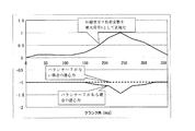
図1〜図4は本発明の実施の形態1に係る密閉型圧縮機を説明するものであって、図1は要部を示す縦断面図、図2は部分を示す平面図、図3はバランスウェイトの動作を示す平面図、図4は回転時の挙動を示す特性図である。なお、以下の説明および図において、同じ部分または相当する部分には同じ符号を付し、一部の説明を省略する。
[Embodiment 1]
1 to 4 illustrate a hermetic compressor according to
(全体構成)
図1において、密閉型圧縮機(以下、「圧縮機」と称す)100は、板からなる円筒状密閉容器11と、円筒状密閉容器11内の上部空間に配置された電動機構12と、円筒状密閉容器11内の下部空間に配置された回転圧縮機構(以下「圧縮機構」と称す)1とを有している。
(overall structure)
In FIG. 1, a hermetic compressor (hereinafter referred to as “compressor”) 100 includes a cylindrical
(電動要素)
電動機構12は、回転子5と固定子6とによって構成され、固定子6は円筒状密閉容器11の上部空間の内周に沿って環状に取り付けられ、回転子5は固定子6の内側に若干の間隙を設けて配置されている。そして、回転子5には、その中心を通り鉛直方向に延びるクランク軸(以下「駆動軸」と称す)3が一体に設けられ、駆動軸3は円筒状密閉容器11に固定された駆動軸軸受4によって軸支されている。
(Electric element)
The electric mechanism 12 includes a
(圧縮機構)
圧縮機構1は、冷媒ガスを吸入して圧縮するものであって、固定側の圧縮要素と可動側の圧縮要素(以下「圧縮機構偏心部」と称す)2とを具備し、圧縮機構偏心部2は駆動軸3に接続され、電動機構12によって回転駆動されるものである。
(Compression mechanism)
The
(運動規制手段)
さらに、回転子5の下端には、圧縮機構偏心部2と重心バランスをとるためのバランスウェイト7が取り付けられている。すなわち、バランスウェイト7は、回転子5の下端に設けられたガイド機構10によって、回転中心から離れる方向(半径方向に同じ)に移動自在に案内され、バネ9によって回転中心側に付勢されている。なお、バネ9は、回転子5が回転した際、バランスウェイト7に作用する遠心力に打ち勝つだけの力を発揮するものである。
一方、駆動軸軸受4の外周の一部には、駆動軸3の回転中心から離れる方向に突出する楕円型のカム機構8が取り付けられ、バランスウェイト7の回転中心側の面(以下「当接面」と称す)7aがカム機構8のカム面8aに当接(摺動)している。
したがって、バランスウェイト7はバネ9によって回転中心側に付勢されているから、バランスウェイト7の当接面7aがカム機構8のカム面8aに当接(摺動)している間は、カム面8aの形状に沿って回転中心からの距離が変動し、一方、駆動軸軸受4の外周4aに当接(摺動)している間は、その円筒面に沿って回転中心からの距離が一定に保たれることになる。
(Exercise control means)
Further, a
On the other hand, an
Accordingly, since the
(動作)
次にバランスウェイト7の動作について説明する。
図3の(a)〜(h)において、以下の説明の便宜上、回転子5が時計回り方向に回転するとし、その回転開始位置を図中の上方向(以下「12時の方向」と称す)と、カム機構8のカム面8aが回転中心から最も遠くなる位置を図中の右方向(以下「3時の方向」と称す)とする。
図3の(a)において、回転子5が12時の位置(回転角が0°に同じ)にあるとき、バランスウェイト7の当接面7aが駆動軸軸受4の外周4aに当接(摺動)しているから、バランスウェイト7は回転中心に最も近い位置にある。
(Operation)
Next, the operation of the
3 (a) to 3 (h), for the convenience of the following description, it is assumed that the
3A, when the
そして、図3の(b)〜(d)において、回転子5の回転(回転角の増加に同じ)によって、バランスウェイト7の当接面7aはカム機構8のカム面8aに当接(摺動)し、除々に回転中心から遠ざかり、そして、回転子5が1/4円だけ回転(回転角が90°に同じ)したところで、バランスウェイト7は回転中心から最も遠ざかっている(図3の(d)参照)。この間、バランスウェイト7の重心位置と回転中心とを結ぶ線と当接面7aの垂線(バネ9の付勢方向に同じ)とが形成する角度(θ)が変動している。
3 (b) to 3 (d), the
さらに、図3の(e)〜(g)において、回転子5の回転によって、バランスウェイト7の当接面7aは、除々に回転中心に近づき、そして、回転子5が1/2円だけ回転(回転角が180°に同じ)したところで、バランスウェイト7は回転中心に最も近づいている(図3の(g)参照)。この間、バランスウェイト7の重心位置と回転中心とを結ぶ線と当接面7aの垂線とが形成する角度(θ)が変動している。
Further, in FIGS. 3E to 3G, due to the rotation of the
さらに、回転子5が1/2円から元の位置(回転角が180°〜360°に同じ)に回転している間は、バランスウェイト7の当接面7aが駆動軸軸受4の外周4aに当接(摺動)しているから、回転に伴って回転中心から距離が変動することはなく、バランスウェイト7は回転中心に最も近い位置にある(図3の(h)参照)。
Further, while the
以上のように、圧縮機100は、回転子5の回転角に応じて、バランスウェイト7の重心が移動(回転中心からの距離が変動)するから、回転する部分(回転子5、駆動軸3、および圧縮機構偏心部)の回転角ごとの遠心力と、同じ回転角における圧縮室(前記固定側の圧縮要素と可動側の圧縮要素とによって形成される)のガス負荷による回転トルクとをバランスすることができる。
As described above, in the
図4において、縦軸は回転する部分に作用する遠心力および圧縮室のガス負荷であり、それぞれ最大1として正規化したものであり、横軸は回転子5(バランスウェイト7に同じ)の回転角(図中、クランク角としている)である。
すなわち、圧縮室のガス圧が変動する回転角に対応して、バランスウェイトの重心が移動して、バランスウェイトに作用する遠心力が圧縮室ガス負荷(圧縮室において冷媒ガスを圧縮する負荷)に起因する回転トルクとバランスしていることが示されている。よって、電動要素の負荷が平準化され回転部の回転角速度の変動が抑えられるから、無用な振動の発生が防止される。
In FIG. 4, the vertical axis represents the centrifugal force acting on the rotating part and the gas load in the compression chamber, normalized to 1 at the maximum, and the horizontal axis represents the rotation of the rotor 5 (same as the balance weight 7). It is an angle (in the figure, it is a crank angle).
That is, the center of gravity of the balance weight moves corresponding to the rotation angle at which the gas pressure in the compression chamber fluctuates, and the centrifugal force acting on the balance weight is applied to the compression chamber gas load (the load that compresses the refrigerant gas in the compression chamber). It is shown to be balanced with the resulting rotational torque. Therefore, the load of the electric element is leveled and fluctuations in the rotational angular velocity of the rotating part are suppressed, so that unnecessary vibrations are prevented from occurring.
以上のように、圧縮機100は、圧縮機構1の駆動軸3の一回転中の重心位置を制御可能にしているので、一回転中に、その回転角に応じて生じるガス圧縮等による回転アンバランスを相殺することができ、さらにその回転アンバランスの発生状況に応じて重心移動軌跡を変化させることができる。
なお、本発明はカム機構8のカム面8aを楕円型に限定したり、バランスウェイト7の当接面7aを平面に限定するものではなく、前記回転アンバランスの発生状況に応じた重心移動軌跡を実現する適宜の形状にすることができる。また、ガイド機構10の構成や、バネ9の形態も限定するものではない。
As described above, since the
In the present invention, the
本発明によれば、簡素な構成によって無用な振動を抑制することができるから、家庭用および業務用の各種圧縮機として広く利用することができる。 According to the present invention, useless vibration can be suppressed with a simple configuration, and therefore it can be widely used as various compressors for home use and business use.
1:圧縮機構、2:圧縮機構偏心部、3:駆動軸、4:駆動軸軸受、4a:駆動軸軸受の外周、5:回転子、6:固定子、7:バランスウェイト、7a:バランスウェイトの当接面、8:カム機構、8a:カム面、9:バネ、10:ガイド機構、11:円筒状密閉容器、12:電動機構、100:密閉型圧縮機。 1: compression mechanism, 2: compression mechanism eccentric part, 3: drive shaft, 4: drive shaft bearing, 4a: outer periphery of drive shaft bearing, 5: rotor, 6: stator, 7: balance weight, 7a: balance weight 8: cam mechanism, 8a: cam surface, 9: spring, 10: guide mechanism, 11: cylindrical sealed container, 12: electric mechanism, 100: hermetic compressor.
Claims (3)
冷媒ガスを圧縮する圧縮機構偏心部を具備する圧縮機構と、
前記回転子と前記圧縮機構偏心部とを連結する駆動軸と、
該駆動軸を回転自在に軸支する駆動軸軸受と、
前記回転子に回転中心からの距離が変動自在に設置されたバランスウェイトと、
前記駆動軸軸受の外周に設置され、前記バランスウェイトが押し付けられるカム面を具備するカム機構と、
前記バランスウェイトを前記カム面に押し付けるための付勢手段と、を有し、
前記回転軸の回転角に応じて前記バランスウェイトの重心位置を変更可能にしたことを特徴とする密閉型圧縮機。 An electric mechanism comprising a stator and a rotor;
A compression mechanism comprising a compression mechanism eccentric portion for compressing the refrigerant gas; and
A drive shaft connecting the rotor and the eccentric portion of the compression mechanism;
A drive shaft bearing that rotatably supports the drive shaft;
A balance weight installed on the rotor so that the distance from the center of rotation is variable;
A cam mechanism provided on an outer periphery of the drive shaft bearing and having a cam surface against which the balance weight is pressed;
Biasing means for pressing the balance weight against the cam surface;
A hermetic compressor, wherein the position of the center of gravity of the balance weight can be changed according to the rotation angle of the rotation shaft.
前記バランスウェイトが、前記カム面に当接する平面状の当接面を具備し、
前記バランスウェイトの重心位置と回転中心とを結ぶ線と、前記当接面とが形成する角度が、前記回転子の回転角に伴って変動することを特徴とする請求項1記載の密閉型圧縮機。 The cam mechanism has an elliptical cam surface;
The balance weight has a flat contact surface that contacts the cam surface,
2. The hermetic compression according to claim 1, wherein an angle formed between a line connecting the center of gravity of the balance weight and the rotation center and the contact surface varies with a rotation angle of the rotor. Machine.
Priority Applications (1)
| Application Number | Priority Date | Filing Date | Title |
|---|---|---|---|
| JP2008319128A JP4920670B2 (en) | 2008-12-16 | 2008-12-16 | Hermetic compressor |
Applications Claiming Priority (1)
| Application Number | Priority Date | Filing Date | Title |
|---|---|---|---|
| JP2008319128A JP4920670B2 (en) | 2008-12-16 | 2008-12-16 | Hermetic compressor |
Publications (3)
| Publication Number | Publication Date |
|---|---|
| JP2010144517A true JP2010144517A (en) | 2010-07-01 |
| JP2010144517A5 JP2010144517A5 (en) | 2010-08-12 |
| JP4920670B2 JP4920670B2 (en) | 2012-04-18 |
Family
ID=42565212
Family Applications (1)
| Application Number | Title | Priority Date | Filing Date |
|---|---|---|---|
| JP2008319128A Expired - Fee Related JP4920670B2 (en) | 2008-12-16 | 2008-12-16 | Hermetic compressor |
Country Status (1)
| Country | Link |
|---|---|
| JP (1) | JP4920670B2 (en) |
Cited By (3)
| Publication number | Priority date | Publication date | Assignee | Title |
|---|---|---|---|---|
| CN106949189A (en) * | 2017-05-03 | 2017-07-14 | 零八电子集团有限公司 | Autobalance rotor deviation of gravity center rotating shaft causes the bascule of eccentric moment |
| CN115419596A (en) * | 2022-09-06 | 2022-12-02 | 珠海凌达压缩机有限公司 | A kind of compressor, air conditioner |
| CN116025566A (en) * | 2023-01-04 | 2023-04-28 | 安徽美芝精密制造有限公司 | Speed fluctuation suppression components and compressors |
Citations (4)
| Publication number | Priority date | Publication date | Assignee | Title |
|---|---|---|---|---|
| JPS62158172A (en) * | 1985-12-29 | 1987-07-14 | 株式会社 香蘭社 | Manufacture of fiber reinforced ceramic |
| JPH0275788A (en) * | 1988-09-09 | 1990-03-15 | Daikin Ind Ltd | rotary compressor |
| JPH036092A (en) * | 1989-06-02 | 1991-01-11 | Nagano Japan Radio Co | Soldering of printed board and apparatus therefor |
| JP2005038291A (en) * | 2003-07-17 | 2005-02-10 | Toshiba Corp | Machine translation apparatus and method, machine translation program |
-
2008
- 2008-12-16 JP JP2008319128A patent/JP4920670B2/en not_active Expired - Fee Related
Patent Citations (4)
| Publication number | Priority date | Publication date | Assignee | Title |
|---|---|---|---|---|
| JPS62158172A (en) * | 1985-12-29 | 1987-07-14 | 株式会社 香蘭社 | Manufacture of fiber reinforced ceramic |
| JPH0275788A (en) * | 1988-09-09 | 1990-03-15 | Daikin Ind Ltd | rotary compressor |
| JPH036092A (en) * | 1989-06-02 | 1991-01-11 | Nagano Japan Radio Co | Soldering of printed board and apparatus therefor |
| JP2005038291A (en) * | 2003-07-17 | 2005-02-10 | Toshiba Corp | Machine translation apparatus and method, machine translation program |
Cited By (4)
| Publication number | Priority date | Publication date | Assignee | Title |
|---|---|---|---|---|
| CN106949189A (en) * | 2017-05-03 | 2017-07-14 | 零八电子集团有限公司 | Autobalance rotor deviation of gravity center rotating shaft causes the bascule of eccentric moment |
| CN106949189B (en) * | 2017-05-03 | 2023-09-05 | 零八一电子集团有限公司 | A balance device that automatically balances the eccentric moment caused by the center of gravity of the rotating shaft deviating from the rotating shaft |
| CN115419596A (en) * | 2022-09-06 | 2022-12-02 | 珠海凌达压缩机有限公司 | A kind of compressor, air conditioner |
| CN116025566A (en) * | 2023-01-04 | 2023-04-28 | 安徽美芝精密制造有限公司 | Speed fluctuation suppression components and compressors |
Also Published As
| Publication number | Publication date |
|---|---|
| JP4920670B2 (en) | 2012-04-18 |
Similar Documents
| Publication | Publication Date | Title |
|---|---|---|
| US9145890B2 (en) | Rotary compressor with dual eccentric portion | |
| JP5035413B2 (en) | Hermetic compressor | |
| AU2016339431B2 (en) | Compressor | |
| CN101205960A (en) | Crankshaft of a reciprocating compressor | |
| JP4920670B2 (en) | Hermetic compressor | |
| JP4752241B2 (en) | Reciprocating compressor | |
| JP2003083395A (en) | Rotary machine | |
| JP2003013995A (en) | Power transmitting mechanism and compressor | |
| JP6632784B2 (en) | Scroll compressor | |
| JP6587747B2 (en) | Scroll compressor | |
| JP2009275566A (en) | Hermetic compressor | |
| JPH0423118B2 (en) | ||
| CN1224813C (en) | Hermetic compressor | |
| JP5100471B2 (en) | Rotary compressor | |
| JP2009024651A (en) | Hermetic rotary compressor and manufacturing method thereof | |
| JP2005201195A (en) | Compressor | |
| CN104728118A (en) | Rotary type compressor | |
| JP2008121554A (en) | Compressor | |
| JP2020007928A (en) | Scroll compressor | |
| KR20110124650A (en) | Hermetic compressor | |
| JP2019056312A (en) | Scroll compressor | |
| JP4855118B2 (en) | Variable capacity compressor | |
| KR100447207B1 (en) | Scroll compressor with outer rotor type motor | |
| KR20170091893A (en) | Rotary compressor | |
| JP2010038084A (en) | Hermetic compressor |
Legal Events
| Date | Code | Title | Description |
|---|---|---|---|
| A521 | Written amendment |
Free format text: JAPANESE INTERMEDIATE CODE: A523 Effective date: 20100528 |
|
| A621 | Written request for application examination |
Free format text: JAPANESE INTERMEDIATE CODE: A621 Effective date: 20100528 |
|
| TRDD | Decision of grant or rejection written | ||
| A977 | Report on retrieval |
Free format text: JAPANESE INTERMEDIATE CODE: A971007 Effective date: 20111227 |
|
| A01 | Written decision to grant a patent or to grant a registration (utility model) |
Free format text: JAPANESE INTERMEDIATE CODE: A01 Effective date: 20120104 |
|
| A01 | Written decision to grant a patent or to grant a registration (utility model) |
Free format text: JAPANESE INTERMEDIATE CODE: A01 |
|
| A61 | First payment of annual fees (during grant procedure) |
Free format text: JAPANESE INTERMEDIATE CODE: A61 Effective date: 20120201 |
|
| R150 | Certificate of patent (=grant) or registration of utility model |
Free format text: JAPANESE INTERMEDIATE CODE: R150 |
|
| FPAY | Renewal fee payment (prs date is renewal date of database) |
Free format text: PAYMENT UNTIL: 20150210 Year of fee payment: 3 |
|
| LAPS | Cancellation because of no payment of annual fees |