JP2010144521A - Electric fan and vacuum cleaner - Google Patents
Electric fan and vacuum cleaner Download PDFInfo
- Publication number
- JP2010144521A JP2010144521A JP2008319237A JP2008319237A JP2010144521A JP 2010144521 A JP2010144521 A JP 2010144521A JP 2008319237 A JP2008319237 A JP 2008319237A JP 2008319237 A JP2008319237 A JP 2008319237A JP 2010144521 A JP2010144521 A JP 2010144521A
- Authority
- JP
- Japan
- Prior art keywords
- impeller
- electric blower
- tip
- contact ring
- circular contact
- Prior art date
- Legal status (The legal status is an assumption and is not a legal conclusion. Google has not performed a legal analysis and makes no representation as to the accuracy of the status listed.)
- Pending
Links
Images



Landscapes
- Electric Suction Cleaners (AREA)
- Structures Of Non-Positive Displacement Pumps (AREA)
- Motor Or Generator Frames (AREA)
- Connection Of Motors, Electrical Generators, Mechanical Devices, And The Like (AREA)
Abstract
【課題】吸込性能に優れた電動送風機を提供する。
【解決手段】電機子(図示せず)の一端に固定され外周に吹き出し口(図示せず)を設けたインペラ11と、電機子のインペラ11側の一端を軸受4を介して支持する負荷側ブラケット5と、電機子の他端を回転自在に支持する反負荷側ブラケット(図示せず)と、吹き出し口からの風を整流するエア−ガイド10と、インペラ11及びエアーガイド10を覆うケーシング(図示せず)とを備え、インペラ11の底面に、先端が鋭角で負荷側ブラケット5側に突出し、その突出部の径が、負荷側ブラケット5の中央部に位置し軸受4を収納するハウジング室127の外径よりも大きい径の円形接触リング124を設け、円形接触リング124の先端をエアーガイド10の底面部に接触させた。
【選択図】図1An electric blower having excellent suction performance is provided.
An impeller fixed to one end of an armature (not shown) and provided with a blowout port (not shown) on the outer periphery, and a load side supporting one end of the armature on the impeller 11 side via a bearing 4 A bracket 5, an anti-load side bracket (not shown) that rotatably supports the other end of the armature, an air guide 10 that rectifies the wind from the outlet, and a casing that covers the impeller 11 and the air guide 10 ( (Not shown), and a housing chamber in which the tip of the impeller 11 protrudes toward the load-side bracket 5 with an acute angle and the diameter of the protrusion is located at the center of the load-side bracket 5 and accommodates the bearing 4 A circular contact ring 124 having a diameter larger than the outer diameter of 127 was provided, and the tip of the circular contact ring 124 was brought into contact with the bottom surface portion of the air guide 10.
[Selection] Figure 1
Description
本発明は、電動送風機及びそれを用いた電気掃除機に関するものである。 The present invention relates to an electric blower and a vacuum cleaner using the same.
従来の電動送風機並びにそれを用いた電気掃除機として、図5〜図7に示されるようなものがあった(例えば、特許文献1参照)。 As a conventional electric blower and a vacuum cleaner using the same, there have been those shown in FIGS. 5 to 7 (for example, see Patent Document 1).
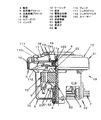
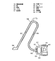
図5は、上記特許文献1に記載された従来の電動送風機の断面図、図6は、同電動送風機の要部拡大断面図、図7は、同電動送風機を用いた従来の電気掃除機の概略構成図である。 FIG. 5 is a cross-sectional view of a conventional electric blower described in Patent Document 1, FIG. 6 is an enlarged cross-sectional view of the main part of the electric blower, and FIG. 7 is a diagram of a conventional electric vacuum cleaner using the electric blower. It is a schematic block diagram.
図5において、従来のこの種の電動送風機19は、モ−タ部32と、ファン部31から構成され、モ−タ部32の51は、整流子52、電機子巻線22を有する電機子で、前記電機子巻線22は、電機子コアー70の外周に巻かれている。前記電機子51は、モ−タ部32の軸53の両端に、軸受4が圧入され、この軸受4を、負荷側ブラケット5と反負荷側ブラケット6にて支持している。7は、カ−ボンブラシ8を内蔵した金属からなるブラシホルダーであり、反負荷側ブラケット6にて保持されている。9は界磁巻線23を有する界磁で、前記界磁巻線23は、界磁コアー72の外周に巻かれている。
In FIG. 5, this type of conventional
ファン部31の10は、負荷側ブラケット5と、負荷であり空気吸引、吹き出し用のインペラ11間に形成した整流用のエア−ガイドであり、インペラ11の上方はケーシング12で覆われている。アルミなどのプレス部品によって組立てられたインペラ11は、複数枚のブレード110を、平面の円板形状からなるシュラウドウシロ112と傘形の円板形状からなるシュラウドマエ111によって挟持しており、焼結や真鍮からなるスペーサー120、板金などからなる座金14、及びナット15により軸53に固定され、軸53とともに回転する。
10 of the
エア−ガイド10は、ネジ(図示せず)等にて負荷側ブラケット5に固定しており、負荷側ブラケット5と反負荷側ブラケット6もネジ(図示せず)等にて固定してある。16は、ケーシング12の吸気口12aを形成する樹脂などからなるタイトキャップであり、ケーシング12の中央部へは溶着等で固定しており、インペラ11の吸込口11aとタイトキャップ16は接触することで、タイト性を確保している。
The
次に、図6を用いて、前記電動送風機の負荷側の軸受け近傍の構成について説明する。 Next, the configuration near the bearing on the load side of the electric blower will be described with reference to FIG.
図6において、軸受4の内部構成は、内輪121と外輪122と、その上下を覆うシール板123a、123bで内部をシールしており、負荷側のシール板123aは、内輪121と非接触、反負荷側のシール板123bは、内輪121と接触する仕様となっている。
In FIG. 6, the internal configuration of the
一般的には、非接触のシール板123aは、鉄、接触する方のシール板123bは、ゴムでそれぞれ構成されている。更に過去の電動送風機19では、負荷側の軸受4の上下2つのシール板123a、123bとも非接触の鉄シールを施してきたが、電気掃除機の吸引性能の向上に伴い、ファン部31内の真空圧が飛躍的に向上し、結果、負荷側の軸受4内部の僅かな隙間を通り、モータ部32側からファン部31側に向って僅かな空気洩れが発生し、その僅かな空気洩れがファン部31の吸引性能の低下要因の一つとなっていた。
In general, the
従って、昨今は、図6に示すように、軸受4の反負荷側のシール板123bを内輪121と接触させることで、モータ部32側からファン部31側に向っての空気洩れを防ぎ、ファン部31の吸引性能向上を図っていた。
Therefore, recently, as shown in FIG. 6, the
このような構造で、従来の電動送風機19は構成されており、作用としてはインペラ11が回転することによって発生する吹き出し風が、インペラ11の吹き出し口11b外周に設けた整流用のエア−ガイド10を通過した後、モ−タ部32の電機子51、界磁9の界磁巻線23を冷却し、反負荷側ブラケット6を通過して後方に排気される。
With such a structure, the conventional
前記電動送風機19が組み込まれた従来の電気掃除機は、図7のような構造となっていた。
The conventional vacuum cleaner incorporating the
図7において、電気掃除機本体61(以下、「本体61」と称す)は、中央部に設けられた格子隔壁53により集塵室81と、モ−タ室82に分けられており、集塵室81には紙袋54が、モ−タ室82には上記電動送風機19が備えつけられている。本体61には、接続パイプ60、ホ−ス59、先端パイプ58、延長管57、ノズル56が順次接続されている。
In FIG. 7, a vacuum cleaner main body 61 (hereinafter referred to as “
上記従来の電気掃除機の作用としては、電動送風機19の吸引力によりノズル56から集められたゴミは、延長管57、先端パイプ58、ホ−ス59、接続パイプ60を通り、集塵室81の紙袋54に集められる。
従来の電動送風機19では、負荷側ブラケット5側の軸受4は、軸受4を構成する内輪121と外輪122の上下を覆う2つのシール板123a、123bについて、一方のシール板123bを内輪と接触させ、その接触させた側を反負荷側に向けて配設することにより、軸受4内部を構成する内輪121と外輪122、及び内輪121と外輪122の上下を覆うシール板123a、123bの僅かな隙間を通り、モータ部32側からファン部31側へ空気が入り込むことを防止し、吸引性能の向上を図ってきた。
In the conventional
しかしながら、ゴム材質からなるシール板123bを、30,000rpm〜45,000rpmという高速回転で接触回転させるために、接触による機械摩擦損失が増加し、空気洩れはほぼゼロ化できるものの、機械摩擦損失が増加し、電動送風機19のトータル効率としては、双方の相殺結果により充分に満足できるレベルではなかった。特に、接触ゴムシール仕様の軸受4は、標準タイプの非接触鉄シール仕様の軸受4と比較すると、価格面で高価であり、前述の電動送風機19のトータル効率の効果を鑑みても、コストの割には電動送風機19の吸引性能の改善効果が少ないという課題があった。
However, since the
本発明は、上記従来の課題を解決するもので、安価な構成で、従来の負荷側の軸受からの空気洩れを防止すると共に、摩擦による機械損失を最小限に抑え、更なる吸込性能の向上を実現した電動送風機を提供することを目的とする。 The present invention solves the above-mentioned conventional problems, and with an inexpensive configuration, prevents air leakage from a conventional load-side bearing, minimizes mechanical loss due to friction, and further improves suction performance. An object is to provide an electric blower that realizes the above.
前記従来の課題を解決するために、本発明の電動送風機は、電機子巻線を有する電機子と、界磁巻線を有する界磁と、前記電機子の一端に固定され外周に空気吹き出し用の吹き出し口を設けたインペラと、前記電機子の前記インペラ側の一端を軸受を介して回転自在に支持する負荷側ブラケットと、前記電機子の他端を軸受を介して回転自在に支持する反負荷側ブラケットと、樹脂からなり前記吹き出し口からの吹き出し風を整流するエア−ガイドと、板金などからなり前記インペラ及び前記エアーガイドを覆うケーシングとを備え、前記インペラの底面に、先端が鋭角で前記負荷側ブラケット側に突出し、その突出部の径が、前記負荷側ブラケットの中央部に位置し前記軸受を収納するハウジング室の外径よりも大きい径の円形接触リングを設け、前記円形接触リングの先端が前記エアーガイドの底面部に接触してなるもので、負荷側軸受の内部隙間を通過するモータ部からファン部への空気の洩れを防止できるとともに、機械損失の抑制による更なる吸引性能の向上と、低価格化を同時に実現した電動送風機を提供することが可能となる。 In order to solve the above-described conventional problems, an electric blower of the present invention includes an armature having an armature winding, a field having a field winding, and an air blower around an outer periphery fixed to one end of the armature. An impeller provided with a blowout opening, a load-side bracket that rotatably supports one end of the armature on the impeller side via a bearing, and a counterbalance that rotatably supports the other end of the armature via a bearing. A load-side bracket; an air guide made of resin that rectifies blown air from the outlet; and a casing that is made of sheet metal and covers the impeller and the air guide. A circular contact ring that protrudes toward the load side bracket and has a diameter larger than the outer diameter of the housing chamber that is located at the center of the load side bracket and houses the bearing Provided, the tip of the circular contact ring is in contact with the bottom surface of the air guide, which can prevent air leakage from the motor part passing through the internal clearance of the load side bearing to the fan part and reduce mechanical loss. It is possible to provide an electric blower that achieves further improvement in suction performance by suppression and reduction in price.
また、本発明の電気掃除機は、塵埃を捕集する集塵室と請求項1〜5のいずれか1項に記載の電動送風機を備え、前記集塵室と前記電動送風機とを連通させたもので、電気掃除機の吸込性能の向上を図ることができる。 Moreover, the vacuum cleaner of this invention was equipped with the dust collection chamber which collects dust, and the electric blower of any one of Claims 1-5, and made the said dust collection chamber and the said electric blower communicate. Therefore, the suction performance of the vacuum cleaner can be improved.
本発明の電動送風機は、負荷側軸受の内部隙間を通過するモータ部からファン部への空気の洩れを防止できるとともに、機械損失の抑制による更なる吸引性能の向上と、低価格化を同時に実現できる。 The electric blower of the present invention can prevent leakage of air from the motor section passing through the internal clearance of the load side bearing to the fan section, and at the same time realizes further improvement in suction performance and reduction in cost by suppressing mechanical loss. it can.
第1の発明は、電機子巻線を有する電機子と、界磁巻線を有する界磁と、前記電機子の一端に固定され外周に空気吹き出し用の吹き出し口を設けたインペラと、前記電機子の前記インペラ側の一端を軸受を介して回転自在に支持する負荷側ブラケットと、前記電機子の他端を軸受を介して回転自在に支持する反負荷側ブラケットと、樹脂からなり前記吹き出し口からの吹き出し風を整流するエア−ガイドと、板金などからなり前記インペラ及び前記エアーガイドを覆うケーシングとを備え、前記インペラの底面に、先端が鋭角で前記負荷側ブラケット側に突出し、その突出部の径が、前記負荷側ブラケットの中央部に位置し前記軸受を収納するハウジング室の外径よりも大きい径の円形接触リングを設け、前記円形接触リングの先端が前記エアーガイドの底面部に接触してなるもので、負荷側軸受の内部隙間を通過するモータ部からファン部への空気の洩れを防止できるとともに、機械損失の抑制による更なる吸引性能の向上と、低価格化を同時に実現した電動送風機を提供することが可能となる。 According to a first aspect of the present invention, there is provided an armature having an armature winding, a field having a field winding, an impeller fixed to one end of the armature and provided with an air outlet for air blowing on the outer periphery, and the electric machine A load-side bracket that rotatably supports one end of the impeller side via a bearing; a counter-load side bracket that rotatably supports the other end of the armature via a bearing; An air guide that rectifies the blown air from the air, and a casing that is made of sheet metal and covers the impeller and the air guide, and protrudes toward the load side bracket with a sharp tip at the bottom of the impeller, and the protruding portion A circular contact ring having a diameter larger than the outer diameter of the housing chamber that houses the bearing and is located at the center of the load side bracket, and the tip of the circular contact ring -It is in contact with the bottom part of the guide, and it can prevent air leakage from the motor part that passes through the internal clearance of the load side bearing to the fan part. It becomes possible to provide an electric blower that can be priced at the same time.
第2の発明は、特に、第1の発明のインペラは、ハウジング室内の軸受の内輪に、焼結や真鍮などからなるスペーサー、板金などからなる座金を介して位置決め、固定され、前記座金に円形接触リングを一体形成したもので、より低価格で同様の効果を得ることが可能となる。 In the second invention, in particular, the impeller of the first invention is positioned and fixed to the inner ring of the bearing in the housing chamber via a spacer made of sintered or brass, a washer made of sheet metal, and the like. Since the contact ring is integrally formed, the same effect can be obtained at a lower price.
第3の発明は、特に、第1の発明のインペラを、中央部に吸気口を有した傘形の円板形状からなるシュラウドマエと、樹脂からなり平らな円板状のシュラウドウシロで、複数枚のブレードを挟持して構成し、前記シュラウドウシロの底面に円形接触リングを一体に形成したもので、より低価格で同様の効果を得ることが可能となる。 According to a third aspect of the invention, in particular, the impeller of the first aspect of the present invention is a shroud mae made of an umbrella-shaped disk having an air inlet in the center and a flat disk-shaped shroud cowro made of resin. It is configured by sandwiching a plurality of blades, and a circular contact ring is integrally formed on the bottom surface of the shroud, so that the same effect can be obtained at a lower price.
第4の発明は、特に、第1〜3のいずれか1つの発明のエアーガイドの底面部に、円形接触リングの先端が接触するPTFEをリング状に配設し、前記円形接触リングの先端と前記PTFEとでエアータイトする構成としたもので、タイト性の大幅向上が図れるとともに、PTFE採用による更なる機械損失の抑制によって更なる吸引性能の向上を図ることが可能となる。 According to a fourth aspect of the present invention, in particular, PTFE with which the tip of the circular contact ring contacts is arranged in a ring shape on the bottom surface of the air guide according to any one of the first to third aspects of the invention. The structure is airtight with the PTFE, so that the tightness can be greatly improved, and the suction performance can be further improved by further suppressing the mechanical loss by adopting PTFE.
第5の発明は、特に、第1〜4のいずれか1つの発明のエアーガイドの底面部の円形接触リングの先端が位置する部分に断面凹形状のラビリンス室を円環状に設け、前記円形接触リング先端を、前記エアーガイドの底面部に接触させる代わりに、前記ラビリンス室内に入り込むようにしたもので、円形接触リングの先端とラビリンス室との間のラビリンス効果により、エアータイトが確保されると共に、接触による機械損失をゼロ化することが可能となる。 In a fifth aspect of the present invention, in particular, a labyrinth chamber having a concave cross section is provided in an annular shape at a portion of the bottom surface of the air guide according to any one of the first to fourth aspects where the tip of the circular contact ring is located. Instead of bringing the ring tip into contact with the bottom surface of the air guide, it enters the labyrinth chamber, and air tightness is secured by the labyrinth effect between the tip of the circular contact ring and the labyrinth chamber. The mechanical loss due to contact can be made zero.
第6の発明は、塵埃を捕集する集塵室と請求項1〜5のいずれか1項に記載の電動送風機を備え、前記集塵室と前記電動送風機とを連通させたもので、電気掃除機の吸込性能の向上を図ることができる。 6th invention is equipped with the dust collection chamber which collects dust, and the electric blower of any one of Claims 1-5, The said dust collection chamber and the said electric blower were connected, and electric The suction performance of the vacuum cleaner can be improved.
以下、本発明の実施の形態について、図面を参照しながら説明する。なお、この実施の形態によって本発明が限定されるものではない。 Hereinafter, embodiments of the present invention will be described with reference to the drawings. Note that the present invention is not limited to the embodiments.
(実施の形態1)
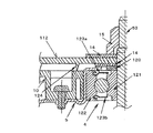
図1は、本発明の第1の実施の形態における電動送風機の要部断面図である。なお、上記従来の電動送風機と同一部分については、同一の符号を付して、その説明を省略する。
(Embodiment 1)
FIG. 1 is a cross-sectional view of a main part of the electric blower according to the first embodiment of the present invention. In addition, about the same part as the said conventional electric blower, the same code | symbol is attached | subjected and the description is abbreviate | omitted.
本実施の形態は、図1に示すように、負荷側の軸受4の反負荷側のシール板123bについても、非接触シール構成、すなわち上下のシール板123a、123b共に非接触の標準軸受としたものである。
In the present embodiment, as shown in FIG. 1, the non-contact seal structure, that is, the upper and
加えて、インペラ11を軸53に固定、位置決めするために、インペラ11のシュラウドウシロ112の底面部には、焼結や真鍮などからなるスペーサー120と、板金などからなる座金14を有し、シュラウドウシロ112の吸引側面部は、座金14を介して、ナット15により軸53に確実に固定されている。この時、シュラウドウシロ112の底面部に位置する座金14について、軸受4を収めた負荷側ブラケット5のハウジング室127の外径Aよりも大きい径とし、座金14の反負荷側外周面には、先端が鋭角に形成された円形接触リング124を形成し、前記円形接触リング124の先端は、樹脂で形成されたエアーガイド10の底面部と接触タイトを行う構成としたものである。
In addition, in order to fix and position the
本実施の形態は、上記のような構成とすることで、インペラ11のシュラウドウシロ112の底面に設けた座金14と、エアーガイド10の中央部間で、接触タイトを実施することができるため、負荷側軸受4の上下シール板123a、123bの両側共に非接触鉄シール仕様であっても、モータ部32側からファン部31側への空気洩れを防ぐことが可能となる。
Since the present embodiment is configured as described above, contact tightness can be performed between the
また、従来の接触ゴムシール仕様の場合は、ゴムと鉄からなる内輪121との接触であったのに対し、本実施の形態では、樹脂と鉄の接触であり、且つ先端部を鋭角な形状で構成していることから、接触による機械摩擦損失を従来構成に較べ低減することができる。また、板金のプレスで作成されることが一般的である座金14に、プレス加工で円形接触リング124を形成するのみであるため、部品追加もなく、僅かな加工費アップのみであり、大幅な価格アップを抑制することも可能である。
Further, in the case of the conventional contact rubber seal specification, it is a contact between the
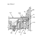
図2は、本実施の形態の他の例を示すもので、インペラ11のシュラウドウシロ112を樹脂で形成した場合に、円形接触リング124を座金14に形成する代わりに、シュラウドウシロ112の底面部に一体成型するようにしても良い。これにより、樹脂成型によって、図2に示すような円形接触リング124を形成することは容易であるとともに、加工費アップもないため、価格アップすることなく同様の効果を得ることが可能となる。
FIG. 2 shows another example of the present embodiment. When the
図3は、本実施の形態の他の例を示すもので、円形接触リング124の先端部が当たるエアーガイド10の底面部に、PTFE(フッ素樹脂)からなるPTFEリング125をリング状に配設したものであるする。PTFEは、円形接触リング124の先端が当たった場合、非常に入り込みがよく、またタイトが確実であるにもかかわらず、接触による摩擦が非常に少ないため、機械摩擦損失を大幅に低減することが可能である。
FIG. 3 shows another example of the present embodiment. A
図4は、本実施の形態の他の例を示すもので、円形接触リング124の先端部が当たるエアーガイド10の底面部に、円形接触リング124の先端部が位置する箇所のみに、断面が凹形状、すなわちラビリンス室126を円環状に設け、円形接触リング124の先端を、ラビリンス室126内に入り込むようにしたもので、これにより、ラビリンス効果でエアータイトが確実に確保されると共に、円形接触リング124の先端部とエアーガイド10の底面部との間の接触をゼロ化することができる。結果、負荷側軸受4の上下2つのシール構成が両側とも非接触鉄シール仕様であった過去の軸受4と同等の機械摩擦損失を維持しながら、吸気洩れを確実に防止するとが可能となる。
FIG. 4 shows another example of the present embodiment. The cross section is shown only at the position where the tip of the
最後に上述で示してきた電動送風機19を、図7に示す本体61に組み込んだ場合には、よりタイト性の向上、すなわちより高効率化を図った電動送風機の搭載が可能となるため、本体61の吸込性能の向上を図ることが可能となるものである。
Finally, when the
以上のように、本発明にかかる電動送風機は、機械摩擦損失を抑えつつ、比較的安価な構成で負荷側軸受を介しての空気洩れを防止することができ、結果、小型・軽量で且つ高効率な吸引性能を得ることが可能であるため、床移動型交流掃除機にかかわらず、小型化が利点となるハンディー型や、縦型、又は直流充電式掃除機等の用途にも使用できるものである。 As described above, the electric blower according to the present invention can prevent air leakage through the load-side bearing with a relatively inexpensive configuration while suppressing mechanical friction loss. Because it is possible to obtain efficient suction performance, it can be used for applications such as handy type, vertical type, or DC rechargeable vacuum cleaner, where downsizing is an advantage, regardless of floor moving type AC vacuum cleaner It is.
4 負荷側軸受
5 負荷側ブラケット
6 反負荷側ブラケット
9 界磁
10 エアーガイド
11 インペラ
12 ケーシング
14 座金
19 電動送風機
22 電機子巻線
23 界磁巻線
51 電機子
52 整流子
53 軸
110 ブレード
111 シュラウドマエ
112 シュラウドウシロ
124 円形接触リング
125 PTFEリング
126 ラビリンス室
127 ハウジング室
DESCRIPTION OF
Claims (6)
Priority Applications (1)
| Application Number | Priority Date | Filing Date | Title |
|---|---|---|---|
| JP2008319237A JP2010144521A (en) | 2008-12-16 | 2008-12-16 | Electric fan and vacuum cleaner |
Applications Claiming Priority (1)
| Application Number | Priority Date | Filing Date | Title |
|---|---|---|---|
| JP2008319237A JP2010144521A (en) | 2008-12-16 | 2008-12-16 | Electric fan and vacuum cleaner |
Publications (1)
| Publication Number | Publication Date |
|---|---|
| JP2010144521A true JP2010144521A (en) | 2010-07-01 |
Family
ID=42565215
Family Applications (1)
| Application Number | Title | Priority Date | Filing Date |
|---|---|---|---|
| JP2008319237A Pending JP2010144521A (en) | 2008-12-16 | 2008-12-16 | Electric fan and vacuum cleaner |
Country Status (1)
| Country | Link |
|---|---|
| JP (1) | JP2010144521A (en) |
Cited By (3)
| Publication number | Priority date | Publication date | Assignee | Title |
|---|---|---|---|---|
| WO2012124001A1 (en) * | 2011-03-16 | 2012-09-20 | パナソニック株式会社 | Electric blower and electric cleaner using same |
| JP2017532499A (en) * | 2014-10-30 | 2017-11-02 | コンチネンタル オートモーティヴ ゲゼルシャフト ミット ベシュレンクテル ハフツングContinental Automotive GmbH | Electric drive pump |
| KR20230118951A (en) | 2021-03-23 | 2023-08-14 | 도시바 에너지시스템즈 가부시키가이샤 | Superconducting coil device, superconducting accelerator and particle beam therapy device |
-
2008
- 2008-12-16 JP JP2008319237A patent/JP2010144521A/en active Pending
Cited By (4)
| Publication number | Priority date | Publication date | Assignee | Title |
|---|---|---|---|---|
| WO2012124001A1 (en) * | 2011-03-16 | 2012-09-20 | パナソニック株式会社 | Electric blower and electric cleaner using same |
| JP2017532499A (en) * | 2014-10-30 | 2017-11-02 | コンチネンタル オートモーティヴ ゲゼルシャフト ミット ベシュレンクテル ハフツングContinental Automotive GmbH | Electric drive pump |
| US10323649B2 (en) | 2014-10-30 | 2019-06-18 | Continental Automotive Gmbh | Electrically driven pump |
| KR20230118951A (en) | 2021-03-23 | 2023-08-14 | 도시바 에너지시스템즈 가부시키가이샤 | Superconducting coil device, superconducting accelerator and particle beam therapy device |
Similar Documents
| Publication | Publication Date | Title |
|---|---|---|
| JP2010180795A (en) | Electric blower | |
| JP2010144521A (en) | Electric fan and vacuum cleaner | |
| JP5316192B2 (en) | Electric blower and electric vacuum cleaner using the same. | |
| JP6375516B2 (en) | Electric blower and electric vacuum cleaner using it | |
| JP2012251530A (en) | Electric blower and vacuum cleaner using the same | |
| JP2011208595A (en) | Electric blower and vacuum cleaner | |
| CN210053306U (en) | Dust collector motor device and dust collector | |
| JP5297161B2 (en) | Electric blower and vacuum cleaner | |
| JP2009095534A (en) | Electric blower | |
| JP5046767B2 (en) | Electric blower and vacuum cleaner provided with the same | |
| JP2009250030A (en) | Electric blower and vacuum cleaner equipped with the same | |
| JP2013199871A (en) | Electric blower | |
| CN210350915U (en) | Motors, blowers and vacuum cleaners | |
| JP4984765B2 (en) | Electric blower | |
| JP2010216364A (en) | Electric blower and vacuum cleaner using the same | |
| JP2018080669A (en) | Electric blower and electric vacuum cleaner using the same | |
| JP5034648B2 (en) | Electric blower and electric vacuum cleaner using the same | |
| JP2009085141A (en) | Electric blower and vacuum cleaner equipped with the same | |
| JP2007211708A (en) | Electric blower and electric vacuum cleaner using the same | |
| JP2001132686A (en) | Centrifugal impeller, electric blower and vacuum cleaner | |
| JP5297160B2 (en) | Electric blower and vacuum cleaner | |
| JP2009232490A (en) | Assembling method of electric air blower, and electric cleaner equipped with electric air blower assembled by using the method | |
| JP2011144757A (en) | Electric blower and vacuum cleaner | |
| JP2008038860A (en) | Electric blower | |
| JP4567994B2 (en) | Electric blower |