JP2010144557A - Exhaust emission control system and exhaust emission control method - Google Patents
Exhaust emission control system and exhaust emission control method Download PDFInfo
- Publication number
- JP2010144557A JP2010144557A JP2008320659A JP2008320659A JP2010144557A JP 2010144557 A JP2010144557 A JP 2010144557A JP 2008320659 A JP2008320659 A JP 2008320659A JP 2008320659 A JP2008320659 A JP 2008320659A JP 2010144557 A JP2010144557 A JP 2010144557A
- Authority
- JP
- Japan
- Prior art keywords
- exhaust gas
- processing unit
- catalyst
- temperature
- dpf
- Prior art date
- Legal status (The legal status is an assumption and is not a legal conclusion. Google has not performed a legal analysis and makes no representation as to the accuracy of the status listed.)
- Granted
Links
Images
Landscapes
- Exhaust Gas After Treatment (AREA)
- Processes For Solid Components From Exhaust (AREA)
- Exhaust Gas Treatment By Means Of Catalyst (AREA)
Abstract
【課題】内燃機関の排気ガス浄化システムにおいて、NOx吸蔵還元型触媒を通過した排気ガスのDPF又は触媒付きDPFへの流量を抑制して、PM再生温度を適温に維持しながら、NOx吸蔵還元型触媒の脱硫制御とDPF又は触媒付きDPFのPM再生処理とを同時に並行して行うことができる排気ガス浄化システム及び排気ガス浄化方法を提供する。
【解決手段】内燃機関10の排気通路16にNOx吸蔵還元型触媒を備えた上流側排気ガス処理ユニット18a,18bと、DPF又は触媒付きDPFを備えた下流側排気ガス処理ユニット18cを設け、前記上流側排気ガス処理ユニット18a,18bを通過する排気ガスG1の流量と、この排気ガスG1の内で、更に前記下流側排気ガス処理ユニット18cを通過する排気ガスG2の流量とを調整可能に構成する。
【選択図】図1In an exhaust gas purification system of an internal combustion engine, a NOx occlusion reduction type is performed while suppressing a flow rate of exhaust gas that has passed through a NOx occlusion reduction type catalyst to a DPF or a DPF with catalyst and maintaining a PM regeneration temperature at an appropriate temperature. Provided are an exhaust gas purification system and an exhaust gas purification method capable of simultaneously performing desulfurization control of a catalyst and PM regeneration processing of a DPF or a DPF with a catalyst in parallel.
SOLUTION: An upstream exhaust gas processing unit 18a, 18b having a NOx occlusion reduction type catalyst and a downstream exhaust gas processing unit 18c having a DPF or a DPF with a catalyst are provided in an exhaust passage 16 of an internal combustion engine 10. The flow rate of the exhaust gas G1 passing through the upstream side exhaust gas processing units 18a and 18b and the flow rate of the exhaust gas G2 passing through the downstream side exhaust gas processing unit 18c within the exhaust gas G1 can be adjusted. To do.
[Selection] Figure 1
Description
本発明は、内燃機関の排気通路に上流側から順にNOx吸蔵還元型触媒(LNT)とDPF(ディーゼルパティキュレートフィルタ)又は触媒付きDPFを備えた排気ガス浄化システムにおいて、排気ガスの流量調整を行うことにより、NOx吸蔵還元型触媒の脱硫制御とDPF又は触媒付きDPFのPM再生処理とを同時に並行して行うことができる排気ガス浄化システム及び排気ガス浄化方法に関する。 The present invention adjusts the flow rate of exhaust gas in an exhaust gas purification system including an NOx storage reduction catalyst (LNT) and a DPF (diesel particulate filter) or a DPF with a catalyst in order from the upstream side in an exhaust passage of an internal combustion engine. Thus, the present invention relates to an exhaust gas purification system and an exhaust gas purification method that can simultaneously perform desulfurization control of a NOx storage reduction catalyst and PM regeneration processing of DPF or DPF with catalyst.
内燃機関の排気ガスを浄化するための装置の一つに、排気ガス中のNOx(窒素酸化物)の浄化のためのNOx浄化触媒装置がある。このNOx浄化触媒装置の一つに、アルカリ金属又はアルカリ土類金属を貴金属と共に担持して、酸素過剰な排気ガス中のNO(一酸化窒素)を酸化して硝酸塩として触媒上に吸着させて、NOxを浄化するNOx吸蔵還元型触媒(LNT:リーンNOxトラップ)を担持した装置がある。 One device for purifying exhaust gas from an internal combustion engine is a NOx purification catalyst device for purifying NOx (nitrogen oxide) in the exhaust gas. In one of these NOx purification catalyst devices, an alkali metal or alkaline earth metal is supported together with a noble metal, NO (nitrogen monoxide) in exhaust gas containing excess oxygen is oxidized and adsorbed on the catalyst as a nitrate, There is an apparatus carrying a NOx occlusion reduction type catalyst (LNT: lean NOx trap) for purifying NOx.
このNOx吸蔵還元型触媒は、排気ガスが酸素過剰なリーン空燃比状態では、NOxを吸蔵し、酸素濃度が低いか、空気過剰率が1より小さいリッチ空燃比状態では、吸蔵したNOxを放出すると共に、この放出されたNOxを還元雰囲気中で還元して、NOxを低減する。 This NOx occlusion reduction type catalyst occludes NOx when the exhaust gas is in a lean air-fuel ratio state in which the oxygen is excessive, and releases NOx occluded in a rich air-fuel ratio state in which the oxygen concentration is low or the excess air ratio is less than 1. At the same time, the released NOx is reduced in a reducing atmosphere to reduce NOx.
このNOx吸蔵還元型触媒は、ディーゼルエンジンのようなリーン空燃比状態が継続すると、NOx吸蔵材であるアルカリ金属又はアルカリ土類金属の殆どが硝酸塩に変化し、触媒上に吸着させた硝酸塩の量が一定量を超えるとNOx吸蔵機能を失い、NOx浄化性能が低下する。そこで、NOx浄化性能を維持するために、NOx吸蔵能力が飽和に達する前に、酸素濃度に対して燃料由来の還元ガス濃度を増加して排気ガス中の酸素濃度を下げて、一時的に空気過剰率λが1以下のリッチ空燃比状態になるようにして、NOx吸蔵材からNOxを放出させるNOx再生処理を行っている。この再生処理は、一定の時間間隔やNOx吸蔵量の蓄積量を監視して、NOx吸蔵能力が飽和に近づいたときに行っている。 In this NOx occlusion reduction type catalyst, when the lean air-fuel ratio state of a diesel engine continues, most of the alkali metal or alkaline earth metal that is the NOx occlusion material changes to nitrate, and the amount of nitrate adsorbed on the catalyst When the amount exceeds a certain amount, the NOx occlusion function is lost, and the NOx purification performance deteriorates. Therefore, in order to maintain the NOx purification performance, before the NOx occlusion capacity reaches saturation, the reducing gas concentration derived from the fuel is increased with respect to the oxygen concentration, and the oxygen concentration in the exhaust gas is lowered to temporarily air. The NOx regeneration process for releasing NOx from the NOx occlusion material is performed so that the excess ratio λ becomes a rich air-fuel ratio state of 1 or less. This regeneration process is performed when the NOx storage capacity approaches saturation by monitoring a certain time interval and the storage amount of the NOx storage amount.
一方、燃料中や潤滑油中に硫黄成分が含まれており、この硫黄成分は二酸化硫黄(SO2)として、内燃機関の筒内(シリンダ内)の燃焼室から排気ガス中に排出された後に、酸化触媒(DOC)やNOx吸蔵還元型触媒(LNT)で三酸化硫黄(SO3)に酸化されて硫黄化合物となる。この硫黄化合物が硫酸塩としてNOx吸蔵還元型触媒上に吸着されるために、NOx吸蔵材のNOx吸蔵能力が低下するという硫黄被毒の問題がある。
この硫黄被毒に対してNOx吸蔵材から硫黄成分を除去する脱硫処理を行ってNOx吸蔵材を再生する必要がある。そのために、NOx吸蔵還元型触媒を700℃程度まで昇温させて、この温度に維持しながら排気ガス中に含まれる燃料量に対して酸素濃度を低下させている。
On the other hand, it includes a sulfur component during and lubricants fuel, as the sulfur component is sulfur dioxide (SO 2), after being discharged into the exhaust gas from the combustion chamber in a cylinder of an internal combustion engine (cylinder) Then, it is oxidized to sulfur trioxide (SO 3 ) by an oxidation catalyst (DOC) or NOx occlusion reduction type catalyst (LNT) to become a sulfur compound. Since this sulfur compound is adsorbed on the NOx occlusion reduction catalyst as a sulfate, there is a problem of sulfur poisoning in which the NOx occlusion capacity of the NOx occlusion material is lowered.
It is necessary to regenerate the NOx storage material by performing a desulfurization process for removing sulfur components from the NOx storage material against the sulfur poisoning. Therefore, the NOx occlusion reduction type catalyst is heated up to about 700 ° C., and the oxygen concentration is lowered with respect to the amount of fuel contained in the exhaust gas while maintaining this temperature.
このNOx再生処理や脱硫処理のための制御では、エンジンの出力を低下させない程度に、シリンダ内への流入空気量を減らして酸素濃度を下げる吸気制御に加えて、排気ガスの一部を再び燃焼室内に戻すEGR(排気再循環)制御を行っている。また、更に、NOx吸蔵還元型触媒に流入する排気ガス中の酸素濃度を更に下げる必要がある場合には、エンジンのシリンダ内燃料噴射制御において、ピストンの膨張行程において燃料を添加するポスト噴射制御や、NOx吸蔵還元型触媒の上流側の排気通路に燃料を直接噴射して、NOx吸蔵還元型触媒に流入する排気ガスの空燃比をリッチにする排気管内直接燃料噴射制御等を行っている。 In the control for NOx regeneration processing and desulfurization processing, in addition to intake control for reducing the oxygen concentration by reducing the amount of air flowing into the cylinder to such an extent that the engine output is not reduced, part of the exhaust gas is burned again. EGR (exhaust gas recirculation) control to return to the room is performed. Further, when it is necessary to further reduce the oxygen concentration in the exhaust gas flowing into the NOx occlusion reduction type catalyst, in the cylinder fuel injection control of the engine, post injection control for adding fuel in the piston expansion stroke, In addition, direct fuel injection control in the exhaust pipe or the like is performed so that the fuel is directly injected into the exhaust passage on the upstream side of the NOx storage reduction catalyst to make the air-fuel ratio of the exhaust gas flowing into the NOx storage reduction catalyst rich.
一方、PM(粒子状物質:パティキュレートマター)を捕集するために、DPF(ディーゼルパティキュレートフィルタ)や触媒付きDPF(SCF)も用いられている。このDPFや触媒付きDPFのフィルタは多孔質のセラミックのハニカムのチャンネルの入口と出口を交互に目封じしたモノリスハニカム型ウォールフロータイプのフィルタ等で形成される。触媒付きDPFでは、このフィルタの部分に白金や酸化セリウム等の触媒を担持する。 On the other hand, in order to collect PM (particulate matter: particulate matter), DPF (diesel particulate filter) and DPF with catalyst (SCF) are also used. The DPF filter or the DPF with catalyst is formed of a monolith honeycomb wall flow type filter or the like in which the inlet and outlet of a porous ceramic honeycomb channel are alternately plugged. In the DPF with catalyst, a catalyst such as platinum or cerium oxide is supported on the filter portion.
このDPFや触媒付きDPFにより、排気ガス中のPMは、多孔質のセラミックの壁で捕集される。このDPFや触媒付きDPFでは、捕集したPMによるフィルタが目詰まりしてくると、PM再生を行っている。このPM再生では、排気通路中に、ポスト噴射制御や排気管内直接燃料噴射制御等により、排気通路中に燃料を供給して、この燃料を、上流側に配置した酸化触媒や、フィルタに担持した触媒により、酸化して排気ガス又は触媒を昇温し、PMの燃焼を行っている。 With this DPF or DPF with catalyst, PM in the exhaust gas is collected by the porous ceramic wall. In this DPF and the DPF with a catalyst, PM regeneration is performed when the collected PM filter becomes clogged. In this PM regeneration, fuel is supplied into the exhaust passage by post injection control, direct fuel injection control in the exhaust pipe, etc., and this fuel is carried on an oxidation catalyst or filter disposed upstream. The catalyst oxidizes and raises the temperature of the exhaust gas or the catalyst to burn PM.
NOx吸蔵還元型触媒(LNT)の後段にDPFや触媒付きDPFが配置されている場合には、脱硫処理においてNOx吸蔵還元型触媒を加熱する過程で高温の排気ガスが、下流側のDPFや触媒付きDPFに流入するので、NOx吸蔵還元型触媒と同時にDPFや触媒付きDPFも加熱できる。 When a DPF or a DPF with a catalyst is disposed downstream of the NOx storage reduction catalyst (LNT), the high-temperature exhaust gas is heated in the process of heating the NOx storage reduction catalyst in the desulfurization process, and the downstream DPF or catalyst. Since it flows into the attached DPF, the DPF and the DPF with catalyst can be heated simultaneously with the NOx storage reduction type catalyst.
これに関連して、内燃機関の排気通路に上流側から酸化触媒、NOxトラップ、粒子フィルタを設けた装置において、フィルタの再生時にNOxトラップの硫黄被毒量を調べて、ある程度進捗していればフィルタの再生操作の終わりに脱硫操作を開始し、また、NOxトラップの飽和率とフィルタの閉塞率のいずれかが閾値を超えた場合にトラップの脱硫操作の終わりに粒子フィルタの再生を実施する酸化窒素トラップの脱硫および粒子フィルタの再生を目的とする方法および装置が提案されている(例えば、特許文献1参照)。 In this connection, if the exhaust passage of the internal combustion engine is provided with an oxidation catalyst, a NOx trap, and a particle filter from the upstream side, the sulfur poisoning amount of the NOx trap is examined at the time of regeneration of the filter. Oxidation that begins the desulfurization operation at the end of the filter regeneration operation and also performs the regeneration of the particle filter at the end of the trap desulfurization operation if either the saturation rate of the NOx trap or the filter clogging rate exceeds a threshold A method and apparatus for desulfurization of a nitrogen trap and regeneration of a particle filter have been proposed (see, for example, Patent Document 1).
また、内燃機関の排気通路の上流側から、燃料添加装置、電気加熱式触媒(EHC)、ターボ過給機、NOx吸蔵還元型触媒(NSR)、NOx及びPMのトラップフィルタ(DPNR)を設け、S再生(脱量処理)又はPM再生の開始後に所定の期間の低負荷運転が継続したときに、EHCに通電し、S再生又はPM再生を継続する内燃機関の排気浄化制御装置が提案されている(例えば、特許文献2参照)。 In addition, a fuel addition device, an electrically heated catalyst (EHC), a turbocharger, a NOx occlusion reduction catalyst (NSR), a NOx and PM trap filter (DPNR) are provided from the upstream side of the exhaust passage of the internal combustion engine, An exhaust purification control device for an internal combustion engine is proposed in which the EHC is energized and continues S regeneration or PM regeneration when low load operation for a predetermined period continues after the start of S regeneration (deamount processing) or PM regeneration. (For example, refer to Patent Document 2).
しかしながら、NOx吸蔵還元型触媒の触媒温度が700℃以上に加熱されていると、下流側のDPFや触媒付きDPFは、このDPFや触媒付きDPFに捕集されたPMの発熱反応により更に高温となる。この高温状態ではDPFや触媒付きDPFのフィルタが溶損される可能性が極めて高くなるという問題がある。
本発明は、上記の状況を鑑みてなされたものであり、その目的は、内燃機関の排気通路に上流側から順にNOx吸蔵還元型触媒とDPF又は触媒付きDPFを備えた排気ガス浄化システムにおいて、NOx吸蔵還元型触媒を通過した排気ガスのDPF又は触媒付きDPFへの流量を抑制して、DPF又は触媒付きDPFへの酸素供給量と、DPF又は触媒付きDPFからの放熱量を減少して、PM再生温度を適温に維持しながら、NOx吸蔵還元型触媒の脱硫制御とDPF又は触媒付きDPFのPM再生処理とを同時に並行して行うことができる排気ガス浄化システム及び排気ガス浄化方法を提供することにある。 The present invention has been made in view of the above situation, and an object of the present invention is to provide an exhaust gas purification system including a NOx storage reduction catalyst and a DPF or a DPF with a catalyst in order from the upstream side in an exhaust passage of an internal combustion engine. Suppressing the flow rate of the exhaust gas that has passed through the NOx storage reduction catalyst to the DPF or the DPF with the catalyst, reducing the amount of oxygen supplied to the DPF or the DPF with the catalyst, and the heat radiation from the DPF or the DPF with the catalyst, Provided are an exhaust gas purification system and an exhaust gas purification method capable of simultaneously performing desulfurization control of a NOx storage reduction catalyst and PM regeneration processing of a DPF or a DPF with a catalyst simultaneously while maintaining the PM regeneration temperature at an appropriate temperature. There is.
上記の目的を達成するための本発明の排気ガス浄化システムは、内燃機関の排気通路にNOx吸蔵還元型触媒を備えた上流側排気ガス処理ユニットと、ディーゼルパティキュレートフィルタ又は触媒付きディーゼルパティキュレートフィルタを備えた下流側排気ガス処理ユニットを設け、前記上流側排気ガス処理ユニットを通過する排気ガスの流量と、前記上流側排気ガス処理ユニットを通過した排気ガスの内で、更に前記下流側排気ガス処理ユニットを通過する排気ガスの流量とを調整可能に構成する。 In order to achieve the above object, an exhaust gas purification system of the present invention includes an upstream side exhaust gas treatment unit having a NOx occlusion reduction catalyst in an exhaust passage of an internal combustion engine, and a diesel particulate filter or a diesel particulate filter with a catalyst. A downstream exhaust gas processing unit, and the downstream exhaust gas among the flow rate of exhaust gas passing through the upstream exhaust gas processing unit and the exhaust gas passing through the upstream exhaust gas processing unit. The flow rate of the exhaust gas passing through the processing unit is configured to be adjustable.
この構成によれば、排気ガスの流量調整を行うことにより、NOx吸蔵還元型触媒を通過する排気ガスの流量と、NOx吸蔵還元型触媒を通過した排気ガスのDPF又は触媒付きDPFへの流量を調整して、DPF又は触媒付きDPFからの放熱と酸素供給量を同時に減少してPM再生温度を適温に維持できるので、NOx吸蔵還元型触媒の脱硫制御とDPF又は触媒付きDPFのPM再生処理とを同時に並行して効率よく行うことができる。特に、DPF又は触媒付きDPFが過熱されるのを防止することができ、この過熱によるフィルタの溶損を回避できる。 According to this configuration, by adjusting the flow rate of the exhaust gas, the flow rate of the exhaust gas that passes through the NOx storage reduction catalyst and the flow rate of the exhaust gas that passes through the NOx storage reduction catalyst to the DPF or the DPF with catalyst are adjusted. By adjusting and reducing the heat release from the DPF or the DPF with catalyst and the oxygen supply amount at the same time and maintaining the PM regeneration temperature at an appropriate temperature, the desulfurization control of the NOx storage reduction type catalyst and the PM regeneration processing of the DPF or catalyst DPF Can be performed efficiently simultaneously in parallel. In particular, the DPF or the DPF with catalyst can be prevented from being overheated, and the filter can be prevented from being damaged by the overheating.
上記の排気ガス浄化システムにおいて、前記排気通路に第1バイパス通路を設け、該第1バイパス通路に前記上流側排気ガス処理ユニットと前記下流側排気ガス処理ユニットを上流側から順に設けて、更に、前記上流側排気ガス処理ユニットの下流側で、かつ、前記下流側排気ガス処理ユニットの上流側の前記第1バイパス通路と前記排気通路を接続する第2バイパス通路を設け、該第2バイパス通路が前記第1バイパス通路と分岐する部分に第1流量制御弁を設け、前記第2バイパス通路が前記排気通路に合流する部分に第2流量制御弁を設けて構成する。 In the exhaust gas purification system, a first bypass passage is provided in the exhaust passage, the upstream exhaust gas processing unit and the downstream exhaust gas processing unit are sequentially provided in the first bypass passage from the upstream side, A second bypass passage connecting the first bypass passage and the exhaust passage on the downstream side of the upstream exhaust gas processing unit and upstream of the downstream exhaust gas processing unit is provided, and the second bypass passage is A first flow rate control valve is provided at a portion branched from the first bypass passage, and a second flow rate control valve is provided at a portion where the second bypass passage merges with the exhaust passage.
この構成によれば、比較的簡単な構成で、第1流量調整制御弁により上流側排気ガス処理ユニットを通過する排気ガスの流量を調整でき、第2流量調整制御弁により下流側排気ガス処理ユニットを通過する排気ガスの流量を調整できる。 According to this configuration, the flow rate of the exhaust gas passing through the upstream side exhaust gas processing unit can be adjusted by the first flow rate adjustment control valve with a relatively simple configuration, and the downstream side exhaust gas processing unit can be adjusted by the second flow rate adjustment control valve. The flow rate of the exhaust gas passing through the can be adjusted.
上記の排気ガス浄化システムにおいて、ポスト噴射又は排気管内直接燃料噴射による排気管内への燃料供給の際に、前記ディーゼルパティキュレートフィルタ又は前記触媒付きディーゼルパティキュレートフィルタのフィルタの温度を指標するフィルタ温度指標温度が第1閾値を超えるまでは、排気ガスの全部を、前記上流側排気ガス処理ユニットと前記下流側排気ガス処理ユニットを通過させ、前記フィルタ温度指標温度が前記第1閾値を越えたときには、排気ガスの一部を、前記上流側排気ガス処理ユニットと前記下流側排気ガス処理ユニットを迂回させると共に、前記上流側排気ガス処理ユニットを通過した排気ガスの内の一部を、下流側排気ガス処理ユニットを迂回させるように構成する。 In the exhaust gas purification system described above, a filter temperature index for indexing a temperature of the diesel particulate filter or the filter of the diesel particulate filter with a catalyst when supplying fuel into the exhaust pipe by post injection or direct fuel injection in the exhaust pipe Until the temperature exceeds the first threshold, all of the exhaust gas passes through the upstream exhaust gas processing unit and the downstream exhaust gas processing unit, and when the filter temperature index temperature exceeds the first threshold, A part of the exhaust gas bypasses the upstream exhaust gas processing unit and the downstream exhaust gas processing unit, and a part of the exhaust gas that has passed through the upstream exhaust gas processing unit is converted into the downstream exhaust gas. Configure to bypass the processing unit.
このフィルタ温度指標温度は、フィルタの温度を直接計測できる場合にはフィルタ温度に対応する温度であるが、一般的にフィルタ温度を直接測定することは難しいため、フィルタに流入する排気ガス温度、言い換えれば、下流側排気ガス処理ユニットの入口側に設けた排気ガス温度センサで検出される排気ガス温度で代用されることが多い。このフィルタ温度指標温度は、フィルタ温度と対応する温度であれば良く、下流側排気ガス処理ユニットの出口側に設けた排気ガス温度センサで検出される排気ガス温度で代用してもよい。 This filter temperature index temperature is a temperature corresponding to the filter temperature when the filter temperature can be directly measured. However, since it is generally difficult to directly measure the filter temperature, the exhaust gas temperature flowing into the filter, in other words, For example, the exhaust gas temperature detected by an exhaust gas temperature sensor provided on the inlet side of the downstream exhaust gas processing unit is often substituted. The filter temperature index temperature may be a temperature corresponding to the filter temperature, and may be substituted with an exhaust gas temperature detected by an exhaust gas temperature sensor provided on the outlet side of the downstream side exhaust gas processing unit.
また、第1閾値は、PM再生処理過程でDPF又は触媒付きDPFのフィルタの溶損を防止しつつ、NOx吸蔵還元型触媒の脱硫処理とフィルタのPM再生処理をするための温度制御に使用する温度であり、フィルタ温度指標温度に対応して決まる温度である。具体的には、NOx吸蔵還元型触媒が脱硫可能な温度(例えば、700℃付近)で、かつ、フィルタがPM燃焼可能な温度(例えば、600℃付近)に同時到達できる温度の上限値(フィルタの入口側の排気ガスの温度に対応する温度としては、例えば、500℃)として設定される。 Further, the first threshold value is used for temperature control for performing desulfurization processing of the NOx storage reduction catalyst and PM regeneration processing of the filter while preventing melting of the filter of the DPF or the DPF with catalyst during the PM regeneration processing. This is a temperature that is determined in accordance with the filter temperature index temperature. Specifically, the upper limit value of the temperature at which the NOx occlusion reduction type catalyst can be desulfurized (for example, around 700 ° C.) and the filter can simultaneously reach the temperature at which PM combustion is possible (for example, near 600 ° C.) (filter The temperature corresponding to the temperature of the exhaust gas on the inlet side is set as 500 ° C., for example.
この構成によれば、フィルタ温度指標温度が第1閾値を超えたときには下流側排気ガス処理ユニットに流入する排気ガスの流量を減少して、下流側排気ガス処理ユニットに流入する排気ガス中の酸素量を減少してPMの燃料反応速度を低下させる。これにより、下流側排気ガス処理ユニットが過熱状態になるのを防止できる。 According to this configuration, when the filter temperature index temperature exceeds the first threshold value, the flow rate of the exhaust gas flowing into the downstream exhaust gas processing unit is reduced, and the oxygen in the exhaust gas flowing into the downstream exhaust gas processing unit is reduced. Decrease amount to reduce PM fuel reaction rate. Thereby, it is possible to prevent the downstream side exhaust gas processing unit from being overheated.
また、上記の目的を達成するための本発明の排気ガス浄化方法は、上記の排気ガス浄化システムにおいて、ポスト噴射又は排気管内直接燃料噴射による排気管内への燃料供給の際に、前記ディーゼルパティキュレートフィルタ又は前記触媒付きディーゼルパティキュレートフィルタのフィルタの温度を指標するフィルタ温度指標温度が第1閾値を超えるまでは、排気ガスの全部を、前記上流側排気ガス処理ユニットと前記下流側排気ガス処理ユニットを通過させ、前記フィルタ温度指標温度が前記第1閾値を越えたときには、排気ガスの一部を、前記上流側排気ガス処理ユニットと前記下流側排気ガス処理ユニットを迂回させると共に、前記上流側排気ガス処理ユニットを通過した排気ガスの内の一部を、下流側排気ガス処理ユニットを迂回させるように構成する。このフィルタ温度指標温度と第1閾値は、上記のフィルタ温度指標温度と第1閾値と同じである。 In addition, the exhaust gas purification method of the present invention for achieving the above object is the above-mentioned diesel particulates in the exhaust gas purification system, when the fuel is supplied into the exhaust pipe by post injection or direct fuel injection in the exhaust pipe. Until the filter temperature index temperature indicating the temperature of the filter or the filter of the diesel particulate filter with catalyst exceeds the first threshold, all of the exhaust gas is removed from the upstream side exhaust gas processing unit and the downstream side exhaust gas processing unit. When the filter temperature index temperature exceeds the first threshold value, a part of the exhaust gas is bypassed between the upstream exhaust gas processing unit and the downstream exhaust gas processing unit, and the upstream exhaust gas is Part of the exhaust gas that has passed through the gas treatment unit bypasses the downstream exhaust gas treatment unit It is configured to. The filter temperature index temperature and the first threshold value are the same as the filter temperature index temperature and the first threshold value.
この方法によれば、排気ガスの流量調整を行うことにより、フィルタ温度指標温度が第1閾値を超えたときには下流側排気ガス処理ユニットに流入する排気ガスの流量を減少して、下流側排気ガス処理ユニットが過熱状態になるのを防止できる。また、下流側排気ガス処理ユニットへの酸素供給量と下流側排気ガス処理ユニットからの放熱量を調整してPM再生温度を適温に維持でき、NOx吸蔵還元型触媒の脱硫制御とDPF又は触媒付きDPFのPM再生処理とを同時に並行して効率よく行うことができる。 According to this method, by adjusting the exhaust gas flow rate, when the filter temperature index temperature exceeds the first threshold, the flow rate of the exhaust gas flowing into the downstream exhaust gas processing unit is reduced, and the downstream exhaust gas is reduced. It is possible to prevent the processing unit from being overheated. Also, the amount of oxygen supplied to the downstream exhaust gas treatment unit and the amount of heat released from the downstream exhaust gas treatment unit can be adjusted to maintain the PM regeneration temperature at an appropriate temperature, with NOx storage reduction catalyst desulfurization control and DPF or with catalyst. The PM regeneration process of the DPF can be efficiently performed simultaneously in parallel.
上記の排気ガス浄化方法において、ポスト噴射又は排気管内直接燃料噴射による排気管内への燃料供給の際に、前記フィルタ温度指標温度が、前記第1閾値より高くなってから、前記第1閾値より低い第2閾値より低くなったときには、前記上流側排気ガス処理ユニットを通過させる排気ガスの流量を増加すると共に、前記上流側排気ガス処理ユニットを通過した排気ガスの内で、前記下流側排気ガス処理ユニットを通過させる排気ガスの流量を増加するように構成する。 In the above exhaust gas purification method, when the fuel is supplied into the exhaust pipe by post injection or direct fuel injection in the exhaust pipe, the filter temperature index temperature becomes higher than the first threshold and then lower than the first threshold. When lower than the second threshold, the flow rate of the exhaust gas passing through the upstream exhaust gas processing unit is increased and the downstream exhaust gas processing is performed in the exhaust gas that has passed through the upstream exhaust gas processing unit. The exhaust gas flow rate passing through the unit is increased.
この第2閾値は、PM再生処理過程でDPF又は触媒付きDPFのフィルタの溶損を防止しつつ、NOx吸蔵還元型触媒の脱硫処理とフィルタのPM再生処理をするための温度制御に使用する温度であり、フィルタ温度指標温度に対応して決まる温度である。具体的には、NOx吸蔵還元型触媒が脱硫可能な温度(例えば、700℃付近)で、かつ、フィルタがPM燃焼可能な温度(例えば、650℃付近)に同時到達できる温度の下限値(フィルタの入口側の排気ガスの温度に対応する温度としては、例えば、450℃)として設定される。 This second threshold is a temperature used for temperature control for desulfurization of the NOx storage reduction catalyst and PM regeneration of the filter while preventing melting of the DPF or DPF filter with catalyst during the PM regeneration process. It is a temperature determined corresponding to the filter temperature index temperature. Specifically, the lower limit of the temperature at which the NOx occlusion reduction catalyst can reach the temperature at which desulfurization is possible (for example, around 700 ° C.) and the filter can simultaneously reach the temperature at which PM combustion is possible (for example, around 650 ° C.). The temperature corresponding to the temperature of the exhaust gas on the inlet side is set as 450 ° C., for example.
この方法によれば、排気ガスのフィルタへの流入流量を抑制することにより、フィルタ温度が低下するが、低下し過ぎるとPMの燃焼除去処理が停止するので、これを避けるため、フィルタ温度が下がりそうな場合には、再びフィルタに流入する排気ガスの流量を増加することができる。 According to this method, by suppressing the flow rate of exhaust gas into the filter, the filter temperature is lowered. However, if the pressure is too low, the PM combustion removal process is stopped. In such a case, the flow rate of the exhaust gas flowing into the filter can be increased again.
つまり、排気ガスの流量の調整により、フィルタに流入する酸素量を調整して、PMとの燃焼反応速度を調整する。排気ガスの流量の減少により、フィルタ温度は低下するが、低下し過ぎるとPM燃焼除去処理が停止するので、この停止を回避するために、フィルタ温度指標温度が第2閾値より低くなると、再び排気ガスの流量を増加する。 That is, the amount of oxygen flowing into the filter is adjusted by adjusting the flow rate of the exhaust gas, and the combustion reaction rate with PM is adjusted. The filter temperature decreases due to the decrease in the flow rate of the exhaust gas, but if it decreases too much, the PM combustion removal process stops. Therefore, when the filter temperature index temperature becomes lower than the second threshold, the exhaust gas is again exhausted to avoid this stop. Increase gas flow.
なお、第1閾値と第2閾値に関しては、ポスト噴射又は排気管内直接燃料噴射による排気管内への燃料供給の際に、下流側排気ガス浄化ユニットのフィルタ温度を制御するために、上限値としての第1閾値と下限値としての第2閾値を用いる。フィルタ温度指標温度は、フィルタ温度を指標する排気ガス温度センサ等の検出値を用いるので、必ずしもフィルタ温度と一致するわけではなく、フィルタ温度指標温度は実際のフィルタ温度に対応する温度となる。 The first threshold value and the second threshold value are set as upper limit values in order to control the filter temperature of the downstream side exhaust gas purification unit when supplying fuel into the exhaust pipe by post injection or direct fuel injection in the exhaust pipe. The first threshold value and the second threshold value as the lower limit value are used. The filter temperature index temperature uses a detection value of an exhaust gas temperature sensor or the like that indexes the filter temperature, and therefore does not necessarily match the filter temperature, and the filter temperature index temperature is a temperature corresponding to the actual filter temperature.
そのため、フィルタ温度指標温度が、第1閾値や第2閾値に到達したときに、第1流量制御弁と第2流量制御弁を使用して、フィルタに流入する排気ガスの流量を調整するわけであるが、制御対象が温度であるため、制御動作に対する応答遅れが発生し、この応答遅れの時間の間に上昇したり、下降したりしてしまう。従って、その応答遅れ分の温度分を見込んで第1閾値と第2閾値を設定することになる。 Therefore, when the filter temperature index temperature reaches the first threshold value or the second threshold value, the flow rate of the exhaust gas flowing into the filter is adjusted using the first flow rate control valve and the second flow rate control valve. However, since the object to be controlled is temperature, a response delay with respect to the control operation occurs, and it rises or falls during this response delay time. Therefore, the first threshold value and the second threshold value are set in consideration of the temperature corresponding to the response delay.
本発明に係る排気ガス浄化システム及び排気ガス浄化方法によれば、内燃機関の排気通路に上流側から順にNOx吸蔵還元型触媒とDPF又は触媒付きDPFを備えた排気ガス浄化システムにおいて、NOx吸蔵還元型触媒装置と触媒付きDPF装置にそれぞれ流入する排気ガスの流量調整を行うことができるように構成したので、内燃機関に対する排気圧力の上昇による乗り心地性(ドライバビリティ)を悪化することなく、NOx吸蔵還元型触媒やDPF又は触媒付きDPFを通過する排気ガスの流量を低減することができる。 According to the exhaust gas purification system and the exhaust gas purification method of the present invention, in an exhaust gas purification system comprising a NOx storage reduction catalyst and a DPF or a DPF with a catalyst in order from the upstream side in the exhaust passage of an internal combustion engine, the NOx storage reduction Since the flow rate of the exhaust gas flowing into each of the type catalyst device and the DPF device with catalyst can be adjusted, NOx is not deteriorated without deteriorating riding comfort (drivability) due to an increase in exhaust pressure to the internal combustion engine. The flow rate of the exhaust gas passing through the storage reduction catalyst, DPF, or DPF with catalyst can be reduced.
このNOx吸蔵還元型触媒を通過した排気ガスの内で、DPF又は触媒付きDPFへ流入する排気ガスの流量を低減することにより、DPF又は触媒付きDPFへの酸素供給量を減少して、過熱状態になることを防止しつつ、PM再生時のフィルタ温度を適温に維持しながら、NOx吸蔵還元型触媒の脱硫制御とDPF又は触媒付きDPFのPM再生処理とを同時に並行して行うことができる。これにより、脱硫処理とフィルタのPM再生処理の処理時間の低減と燃費の低減が可能となる。 By reducing the flow rate of the exhaust gas flowing into the DPF or the DPF with the catalyst in the exhaust gas that has passed through the NOx storage reduction catalyst, the oxygen supply amount to the DPF or the DPF with the catalyst is reduced, and the overheated state While maintaining the filter temperature at the time of PM regeneration at an appropriate temperature, the desulfurization control of the NOx occlusion reduction catalyst and the PM regeneration processing of the DPF or the DPF with catalyst can be performed simultaneously in parallel. This makes it possible to reduce the processing time and fuel consumption of the desulfurization process and the PM regeneration process of the filter.
また、NOx吸蔵還元型触媒及びフィルタを通過する排気ガスの流量を抑制して、NOx吸蔵還元型触媒及びDPF又は触媒付きDPFから排気ガスへの放熱量を低減することができるので、これらの装置の保温と、これらの保温に伴う燃費の低減が可能となる。 Further, since the flow rate of the exhaust gas passing through the NOx storage reduction catalyst and the filter can be suppressed, the amount of heat released from the NOx storage reduction catalyst and DPF or the DPF with catalyst to the exhaust gas can be reduced. It is possible to reduce the fuel consumption associated with the heat retention and the heat retention.
以下、本発明に係る実施の形態の排気ガス浄化方法及び排気ガス浄化システムについて、図面を参照しながら説明する。なお、ここでは、触媒付きDPFを用いて説明しているが、本発明は触媒付きDPFの代わりに、触媒を担持していないDPFを用いる排気ガス浄化システムも適用できる。 Hereinafter, an exhaust gas purification method and an exhaust gas purification system according to embodiments of the present invention will be described with reference to the drawings. In addition, although demonstrated using DPF with a catalyst here, the present invention can also apply an exhaust gas purification system using DPF which does not carry a catalyst instead of DPF with a catalyst.
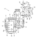
図1に、本発明に係る実施の形態の排気ガス浄化システム1の構成を示す。この排気ガス浄化システム1は、エンジン(内燃機関)10の排気通路16に排気ガス浄化装置18を備えて構成される。
FIG. 1 shows a configuration of an exhaust gas purification system 1 according to an embodiment of the present invention. The exhaust gas purification system 1 includes an exhaust
この排気ガス浄化システム1のエンジン10は、吸気マニホールド10aに接続される吸気通路11に吸入吸気量センサ12(MAFセンサ)とターボチャージャ13のコンプレッサ13aとインタークーラ14と吸気弁(インテークスロットル)15を備えている。さらに、排気マニホールド10bに接続される排気通路16に、ターボチャージャ13のタービン13bと、排気管内に直接燃料を噴射するための燃料噴射装置17と排気ガス浄化装置18を備えている。更に、排気マニホールド10bと吸気マニホールド10aを接続するEGR通路19には、EGRクーラー20とEGR弁21を備えている。
The
排気ガス浄化装置18は、図1の構成では、酸化触媒装置(DOC)18a、NOx吸蔵還元型触媒装置(LNT)18b、触媒付きDPF装置(CSF)18cで構成されている。この排気ガス浄化装置18では、排気ガスGの浄化性能を維持するために、担持している触媒の温度を触媒活性化温度以上のある程度の温度まで上昇させる必要がある。
酸化触媒装置18aは、多孔質のセラミックのハニカム構造の担持体に、白金等の酸化触媒を担持させて形成される。この酸化触媒は、排気ガス中のHCやCOを酸化して排気ガスを浄化する役割と、NOx吸蔵還元型触媒のNOx吸蔵能力を回復するためのNOx再生の際にNOxの還元剤として供給される燃料の一部を酸化して排気ガスの温度を昇温する役割とを持っている。
In the configuration of FIG. 1, the exhaust
The
NOx吸蔵還元型触媒装置18bは、アルカリ金属又はアルカリ土類金属を貴金属と共に担持して形成され、酸素過剰な排気ガス中のNOを酸化して硝酸塩として触媒上に吸着させて、NOxを浄化する。このNOx吸蔵還元型触媒は、排気ガスがリーン空燃比では、NOxを吸蔵し、リッチ空燃比では、吸蔵したNOxを放出すると共に、この放出されたNOxを還元雰囲気中で還元して、NOxを低減する。
The NOx occlusion reduction
触媒付きDPF装置18cは、排気ガス中の粒子状物質(PM)を捕集するためのディーゼルパティキュレートフィルタ(DPF)を備えた触媒付きDPFで構成される。この触媒付きDPFは、多孔質のセラミックのハニカムのチャンネルの入口と出口を交互に目封じしたモノリスハニカム型ウォールフロータイプのフィルタ等で形成される。このフィルタの部分に白金や酸化セリウム等の触媒を担持する。
The catalyzed
この触媒付きDPFにより、排気ガス中のPMは、多孔質のセラミックの壁で捕集される。このPMの捕集量が増加した場合には、排気ガス中に燃料を噴射して、この燃料を酸化触媒により酸化して排気ガスの温度を高めて、この高温の排気ガスにより触媒付きDPFをPMの燃焼開始温度まで上昇させて、捕集されたPMを強制的に燃焼除去して、触媒付きDPFのPM再生を行う。 By this DPF with catalyst, PM in the exhaust gas is collected by the porous ceramic wall. When the amount of collected PM increases, fuel is injected into the exhaust gas, the fuel is oxidized by an oxidation catalyst to raise the temperature of the exhaust gas, and the DPF with the catalyst is made up by the hot exhaust gas. The PM is increased to the combustion start temperature of PM, and the collected PM is forcibly burned and removed to perform PM regeneration of the DPF with catalyst.
本発明では、排気ガス浄化装置18においては、酸化触媒装置18aとNOx吸蔵還元型触媒装置18bとで、NOx吸蔵還元型触媒を備えた上流側排気ガス処理ユニットを構成し、触媒付きDPF装置18cで触媒付きDPFを備えた下流側排気ガス処理ユニットを構成する。
In the present invention, in the exhaust
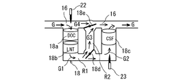
そして、排気ガス浄化装置18は、排気通路16に第1バイパス通路R1を設け、この第1バイパス通路R1に上流側排気ガス処理ユニット18a,18bと下流側排気ガス処理ユニット18cを上流側から順に設けて構成される。更に、上流側排気ガス処理ユニット18a,18bの下流側で、かつ、下流側排気ガス処理ユニット18cの上流側の第1バイパス通路R1と排気通路16を接続する第2バイパス通路R2を設ける。この第2バイパス通路R2が第1バイパス通路R1と分岐する部分に第1流量制御弁18dを設け、第2バイパス通路R2が排気通路16に合流する部分に第2流量制御弁18eを設ける。
The exhaust
この第1流量調整弁18dは、NOx吸蔵還元型触媒装置18bを通過した排気ガスG1の流量の全部又は一部が触媒付きDPF装置18cに流入できるように弁開度を調整可能に構成される。また、第2流量調整弁18eは、触媒付きDPF装置18cを迂回した排気ガスG3(図2参照)が大気に放出するための開放弁となるように構成される。
The first flow
つまり、第1流量制御弁18dと第2流量制御弁18eの弁開度の調整により、図1及び図2に示すように、上流側排気ガス処理ユニット18a,18bを通過する排気ガスG1の流量と、上流側排気ガス処理ユニット18a,18bを通過した排気ガスG1の内で、更に下流側排気ガス処理ユニット18cを通過する排気ガスG2の流量とを調整可能に構成する。
That is, the flow rate of the exhaust gas G1 passing through the upstream side exhaust
更に、図1に示すように、排気ガスGの温度を測定するために、排気ガス浄化装置18の入口に第1温度センサ22が、NOx吸蔵還元型触媒装置18bの出口側である、触媒付きDPF装置18cの入口に、第2温度センサ23が配設される。また、排気ガス浄化装置18の出口に第3温度センサ24とλ(空気過剰率)センサ25が配設される。
Further, as shown in FIG. 1, in order to measure the temperature of the exhaust gas G, a
この第1温度センサ22で検出された温度Tg1が、NOx吸蔵還元型触媒装置18cの触媒温度の制御に必要な温度を検出するための温度となり、第2温度センサ23で検出された温度Tg2が、排気ガスの第1流量制御弁18d、18eの弁開度の制御に必要な温度を検出するための温度となる。また、第3温度センサ24で検出された温度Tg3が排気ガス浄化装置18の異常高温を検出するための温度となる。また、λセンサ25で検出された空気過剰率(又は空燃比、酸素濃度)が、リーン空燃比制御やリッチ空燃比制御に使用される。
The temperature Tg1 detected by the
これらのセンサ22、23、24、25等の測定値とエンジン10の運転制御に必要なデータを入力してエンジンの運転状態と排気ガス浄化システム1の排気ガス浄化制御や再生制御を行う制御装置(図示しない)が設けられている。この制御装置はECU(エンジンコントロールユニット)と呼ばれる制御装置であり、本発明の排気ガス浄化方法に関する制御では、エンジン10からのデータと吸入空気量センサ12等の検出値に基づいて、吸気弁15、排気管内直接燃料噴射用の燃料噴射装置17、第1流量制御弁18d、第2流量制御弁18e、EGR弁22等を制御する。
A control device for inputting measured values of these
なお、燃料噴射装置17は、触媒付きDPF装置18cのPM再生用だけでなく、NOx吸蔵還元型触媒装置18bのNOx再生処理用や脱硫処理用に使用され、更に、排気ガスの昇温用だけでなく、排気ガス中の酸素濃度を調整する空燃比制御にも使用される。
The
この構成の排気ガス浄化システム1によれば、比較的簡単な構成で、第1流量調整制御弁18dにより上流側排気ガス処理ユニット18a,18bを通過する排気ガスG1の流量を調整でき、第2流量調整制御弁18eにより下流側排気ガス処理ユニット18dを通過する排気ガスG2の流量を調整できる。
According to the exhaust gas purification system 1 having this configuration, the flow rate of the exhaust gas G1 passing through the upstream side exhaust
従って、この構成によって、排気ガスG1,G2,G3,G4の流量調整を行うことにより、NOx吸蔵還元型触媒装置18bを通過する排気ガスG1の流量と、NOx吸蔵還元型触媒装置18bを通過した排気ガスG1の内で触媒付きDPF装置18cへ流入する排気ガスG2の流量を調整して、触媒付きDPF装置18cへの酸素供給量と、触媒付きDPF装置18cからの放熱量を調整してPM再生温度を適温に維持できる。そのため、NOx吸蔵還元型触媒装置18bの脱硫制御と触媒付きDPF装置18cのPM再生処理とを同時に並行して効率よく行うことができる。特に、触媒付きDPF装置18cが過熱されるのを防止することができ、この過熱による触媒付きDPF装置18cのフィルタの溶損を回避できる。
Therefore, by adjusting the flow rates of the exhaust gases G1, G2, G3, and G4 with this configuration, the flow rate of the exhaust gas G1 passing through the NOx storage
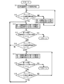
次に、上記の構成の排気ガス浄化システム1における排気ガス浄化方法について、図3の脱硫処理及びPM再生処理の制御フローを参照しながら説明する。この図3の制御フローは、NOx吸蔵還元型触媒装置18bの脱硫処理と触媒付きDPF装置18cのPM再生処理とを同時に行う際に上級の制御フローから繰り返し呼ばれて、実行されて、実行後に上級の制御フローに戻るものとして示してある。
Next, an exhaust gas purification method in the exhaust gas purification system 1 having the above configuration will be described with reference to the control flow of the desulfurization process and the PM regeneration process in FIG. The control flow of FIG. 3 is repeatedly called and executed from the advanced control flow when the desulfurization process of the NOx occlusion reduction
この排気ガス浄化方法では、フィルタ温度指標温度Tcと第1閾値T1と第2閾値T2を用いる。このフィルタ温度指標温度Tcは、触媒付きDPF装置18cのフィルタの温度を直接計測できる場合にはこの測定した温度であるが、一般的にフィルタ温度を直接測定することは難しいため、フィルタに流入する排気ガス温度、言い換えれば、下流側排気ガス処理ユニット18cの入口側に設けた第2温度センサ(排気ガス温度センサ)23で検出される排気ガス温度Tg2で代用する。このフィルタ温度指標温度Tcは、フィルタ温度と対応する温度であれば良いので、下流側排気ガス処理ユニット18cの出口側に設けた第3温度センサ(排気ガス温度センサ)24で検出される排気ガス温度Tg3で代用してもよい。
In this exhaust gas purification method, the filter temperature index temperature Tc, the first threshold value T1, and the second threshold value T2 are used. The filter temperature index temperature Tc is the measured temperature when the temperature of the filter of the DPF device with
また、第1閾値T1は、PM再生処理過程で触媒付きDPF装置18cのフィルタの溶損を防止しつつ、NOx吸蔵還元型触媒装置18bの脱硫処理とフィルタのPM再生処理をするための温度制御に使用する温度であり、フィルタ温度指標温度Tcに対応して決まる温度である。具体的には、NOx吸蔵還元型触媒における脱硫可能な温度(例えば、700℃付近)と、かつ、フィルタにおけるPMの燃焼が可能な温度(例えば、600℃付近)に同時到達できる温度の上限値(フィルタの入口側の排気ガスの温度Tg2に対応する温度としては、例えば、500℃)として設定される。
The first threshold value T1 is a temperature control for performing desulfurization processing of the NOx occlusion reduction
また、第2閾値は、PM再生処理過程で触媒付きDPF装置18cのフィルタの溶損を防止しつつ、NOx吸蔵還元型触媒装置18bの脱硫処理とフィルタのPM再生処理をするための温度制御に使用する温度であり、フィルタ温度指標温度Tcに対応して決まる温度である。具体的には、NOx吸蔵還元型触媒が脱硫可能な温度(例えば、700℃付近)に、かつ、フィルタがPM燃焼可能な温度(例えば、650℃付近)に同時到達できる温度の下限値(フィルタの入口側の排気ガスの温度Tg2に対応する温度としては、例えば、450℃)として設定される。
The second threshold value is used for temperature control for performing desulfurization processing of the NOx occlusion reduction
この排気ガス浄化方法を実施するための図3の制御フローでは、脱硫処理とPM再生処理を行う場合に上級の制御フローから呼ばれてスタートすると、ステップS11で、シリンダ内の燃料噴射制御におけるポスト噴射、又は、燃料噴射装置17による排気通路16内へ燃料を供給する。それと共に、脱硫処理とPM再生処理の継続時間Tiをリセットする。 この際に、次のステップS12で、触媒付きDPF装置18cのフィルタの温度を指標するフィルタ温度指標温度Tcを判定する。この判定でフィルタ温度指標温度Tcが第1閾値T1以下(NO)のときには、ステップS13で、図1に示すように、第1流量制御弁18dを閉弁制御して第2バイパス通路R2を全閉すると共に、第2流量制御弁18eを閉弁制御して第2バイパス通路R2の下流側の排気通路16を全閉する。その後、ステップS12に戻る。
In the control flow of FIG. 3 for carrying out this exhaust gas purification method, when the desulfurization process and the PM regeneration process are performed and started from an advanced control flow, the post in the fuel injection control in the cylinder is started in step S11. The fuel is supplied into the
これにより、排気ガスGの全部を、上流側排気ガス処理ユニット18a,18bと下流側排気ガス処理ユニット18cを通過させる(G1=G2=G)。その後、ステップS12に戻り、フィルタ温度指標温度Tcが第1閾値T1より高く(YES)なるまで、ステップS13を繰り返す。
As a result, the entire exhaust gas G passes through the upstream side exhaust
また、ステップS12で、フィルタ温度指標温度Tcが第1閾値T1より高い(YES)ときには、ステップS14で、図2に示すように、第1流量制御弁18dを第1弁開度θ1まで開弁制御して第2バイパス通路R2を開くと共に、第2流量制御弁18eを第2弁開度θ2まで開弁制御して第2バイパス通路R2の下流側の排気通路16を開く。それと共に、脱硫処理とPM再生処理の継続時間Tiをカウントする。その後、ステップS15に行く。
When the filter temperature index temperature Tc is higher than the first threshold value T1 in step S12 (YES), the first
これにより、排気ガスGの一部の排気ガスG4を、上流側排気ガス処理ユニット18a,18bと下流側排気ガス処理ユニット18cを迂回させて、残りの排気ガスG1を上流側排気ガス処理ユニット18a,18bを通過させる。それと共に、上流側排気ガス処理ユニット18a,18bを通過した排気ガスG1の内の一部の排気ガスG3を、下流側排気ガス処理ユニット18cを迂回させて、残りの排気ガスG2を下流側排気ガス処理ユニット18cに流入させる(G=G1+G4,G1=G2+G3)。
Thus, a part of the exhaust gas G4 of the exhaust gas G bypasses the upstream side exhaust
このステップS14によれば、フィルタ温度指標温度Tcが第1閾値T1を超えたときには下流側排気ガス処理ユニット18cに流入する排気ガスG2の流量を減少するので、下流側排気ガス処理ユニット18cに流入する排気ガスG1中の酸素量が減少してPMの燃料反応速度が低下する。これにより、下流側排気ガス処理ユニット18cが過熱状態になるのが回避される。
According to this step S14, when the filter temperature index temperature Tc exceeds the first threshold value T1, the flow rate of the exhaust gas G2 flowing into the downstream side exhaust
また、上流側排気ガス処理ユニット18a,18bに流入する排気ガスG1の流量が減少するので、上流側排気ガス処理ユニット18a,18bからの放熱量が減少する。更に、下流側排気ガス処理ユニット18cへ流入する排気ガスG2の流量が減少するので、下流側排気ガス処理ユニット18cからの放熱量が減少する。また、下流側排気ガス処理ユニット18cへの酸素供給量が減少するので、フィルタが過熱されるのを回避でき、PM再生温度が適温に維持され、NOx吸蔵還元型触媒の脱硫制御とDPF又は触媒付きDPFのPM再生処理とを同時に並行して効率よく行うことができる。
Further, since the flow rate of the exhaust gas G1 flowing into the upstream side exhaust
ステップS15では、脱硫処理とPM再生処理が終了したか否かを判定し、終了した場合はリターンに行く。終了していない場合はステップS16に行く。この終了の判定は、脱硫処理とPM再生処理の継続時間Tiが予め設定した終了用判定時間Ticを超えたか否かで判定する。 In step S15, it is determined whether or not the desulfurization process and the PM regeneration process have been completed. If not completed, the process goes to step S16. This end determination is made based on whether or not the duration Ti of the desulfurization process and the PM regeneration process exceeds a preset end determination time Tic.
ステップS16では、フィルタ温度指標温度Tcを判定し、フィルタ温度指標温度Tcが第1閾値T1より低い第2閾値T2より低くなったか否かを判定する。そして、フィルタ温度指標温度Tcが第2閾値T2より高い(NO)間は、ステップS14に戻る。また、フィルタ温度指標温度Tcが第2閾値T2より低くなった(YES)ときには、ステップS17で、第1流量制御弁18dを第3弁開度θ3(<θ1)まで閉弁制御して第2バイパス通路R2をやや閉じると共に、第2流量制御弁18eを第4弁開度θ4(<θ2)まで閉弁制御して第2バイパス通路R2の下流側の排気通路16をやや閉じる。それと共に、脱硫処理とPM再生処理の継続時間Tiをカウントする。その後、ステップS18に行く。
In step S16, the filter temperature index temperature Tc is determined, and it is determined whether or not the filter temperature index temperature Tc is lower than a second threshold value T2 lower than the first threshold value T1. And while filter temperature index temperature Tc is higher than 2nd threshold value T2 (NO), it returns to step S14. When the filter temperature index temperature Tc is lower than the second threshold value T2 (YES), the first flow
これにより、上流側排気ガス処理ユニット18a,18bを通過させる排気ガスG1の流量を増加すると共に、上流側排気ガス処理ユニット18a,18bを通過した排気ガスG1の内で、下流側排気ガス処理ユニット18cを通過させる排気ガスG2の流量を増加する。
As a result, the flow rate of the exhaust gas G1 passing through the upstream side exhaust
このステップS17によれば、下流側排気ガス処理ユニット18cのフィルタの温度が下がりそうな場合には、下流側排気ガス処理ユニット18cに流入する排気ガスG2の流量を増加することができ、フィルタの温度が低下し過ぎて下流側排気ガス処理ユニット18cにおけるPMの燃焼除去処理が停止するのを回避できる。
According to this step S17, when the temperature of the filter of the downstream exhaust
ステップS18では、ステップS15と同様に、脱硫処理とPM再生処理が終了したか否かを判定し、終了した場合はリターンに行く。終了していない場合はステップS19に行く。この終了の判定は、脱硫処理とPM再生処理の継続時間Tiが予め設定した終了用判定時間Ticを超えたか否かで判定する。 In step S18, as in step S15, it is determined whether or not the desulfurization process and the PM regeneration process have been completed. If not completed, the process goes to step S19. This end determination is made based on whether or not the duration Ti of the desulfurization process and the PM regeneration process exceeds a preset end determination time Tic.
次のステップS19では、ステップS12と同様に、フィルタ温度指標温度Tcを判定する。この判定でフィルタ温度指標温度Tcが第1閾値T1以下(NO)のときには、ステップS17に行く。また、この判定でフィルタ温度指標温度Tcが第1閾値T1より高い(YES)のときには、ステップS14に行く。 In the next step S19, the filter temperature index temperature Tc is determined as in step S12. If the filter temperature index temperature Tc is equal to or lower than the first threshold value T1 (NO) in this determination, the process goes to step S17. If the filter temperature index temperature Tc is higher than the first threshold T1 (YES) in this determination, the process goes to step S14.
そして、図3の制御フローで、脱硫処理とPM再生処理を終了してリターンに行くと、上級の制御フローに戻り、第1流量制御弁18dと第2流量制御弁18eとは両方とも、通常運転で使用される全閉状態にされる。そして、次の脱硫処理とPM再生処理の開始まで待って、開始になると、再度、上級の制御フローからこの図3の制御フローが呼ばれて実行される。
Then, in the control flow of FIG. 3, when the desulfurization process and the PM regeneration process are finished and return is made, the control flow returns to the advanced control flow, and both the first flow
この図3の制御フローに基づく排気ガス浄化方法によれば、上記の排気ガス浄化システム1において、ポスト噴射又は排気管内直接燃料噴射による排気管内への燃料供給の際に、触媒付きDPFのフィルタの温度を指標するフィルタ温度指標温度Tcが第1閾値T1を越えるまでは、排気ガスGの全部を、上流側排気ガス処理ユニット18a,18bと下流側排気ガス処理ユニット18cを通過させ、フィルタ温度指標温度Tcが第1閾値T1を越えたときには、排気ガスGの一部G4を、上流側排気ガス処理ユニット18a,18bと下流側排気ガス処理ユニット18cを迂回させると共に、上流側排気ガス処理ユニット18a,18bを通過した排気ガスG1の内の一部G3を、下流側排気ガス処理ユニット18cを迂回させることができる。
According to the exhaust gas purification method based on the control flow of FIG. 3, in the exhaust gas purification system 1 described above, when the fuel is supplied into the exhaust pipe by post injection or direct fuel injection in the exhaust pipe, the filter of the DPF with catalyst is used. Until the filter temperature index temperature Tc indicating the temperature exceeds the first threshold value T1, all of the exhaust gas G passes through the upstream side exhaust
また、ポスト噴射又は排気管内直接燃料噴射による排気管内への燃料供給の際に、フィルタ温度指標温度Tcが、第1閾値T1より高くなってから、第1閾値T1より低い第2閾値T2より低くなったときには、上流側排気ガス処理ユニット18a,18bを通過させる排気ガスG1の流量を増加すると共に、上流側排気ガス処理ユニット18a,18bを通過した排気ガスG1の内で、下流側排気ガス処理ユニット18cを通過させる排気ガスG2の流量を増加することができる。
In addition, when fuel is supplied into the exhaust pipe by post injection or direct fuel injection in the exhaust pipe, the filter temperature index temperature Tc becomes higher than the first threshold T1, and then lower than the second threshold T2 lower than the first threshold T1. When this happens, the flow rate of the exhaust gas G1 passing through the upstream side exhaust
更に、脱硫処理とPM再生処理の継続時間Tiが予め設定した終了用判定時間Ticを超えた場合に脱硫処理とPM再生処理を終了することができる。 Furthermore, the desulfurization process and the PM regeneration process can be terminated when the duration time Ti of the desulfurization process and the PM regeneration process exceeds a preset end determination time Tic.
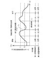
この図3の制御フローでは、図4に示すように、フィルタ温度指標温度Tcが、第1閾値T1より高くなってから、第2閾値T2より低くなるまでは、第1流量制御弁18dを第1弁開度θ1に維持し、第2流量制御弁18eを第2弁開度θ2に維持し、また、フィルタ温度指標温度Tcが、第1閾値T2より低くなってから、再度、第1閾値T1より高くなるまでは、第1流量制御弁18dを第3弁開度θ3に維持し、第2流量制御弁18eを第4弁開度θ4に維持する。
In the control flow of FIG. 3, as shown in FIG. 4, the first flow
そして、上記の排気ガス浄化システム1及び排気ガス浄化方法によれば、エンジン10の排気通路16に上流側から順にNOx吸蔵還元型触媒装置18bと触媒付きDPF装置18cを備えた排気ガス浄化システム1において、NOx吸蔵還元型触媒装置18bと触媒付きDPF装置18cにそれぞれ流入する排気ガスG1,G2の流量調整を行うことができるように構成したので、エンジン10に対する排気圧力の上昇による乗り心地性(ドライバビリティ)を悪化することなく、NOx吸蔵還元型触媒装置18bや触媒付きDPF装置18cを通過する排気ガスG1,G2の流量を低減することができる。
Then, according to the exhaust gas purification system 1 and the exhaust gas purification method described above, the exhaust gas purification system 1 including the NOx occlusion reduction
また、NOx吸蔵還元型触媒装置18bを通過した排気ガスG1の内で、触媒付きDPF装置18cへ流入する排気ガスG2の流量を低減することにより、触媒付きDPF装置18cへの酸素供給量を減少して、過熱状態になることを防止しつつ、PM再生時のフィルタ温度を適温に維持しながら、NOx吸蔵還元型触媒装置18bの脱硫制御と触媒付きDPF装置18cのPM再生処理とを同時に並行して行うことができる。これにより、脱硫処理とフィルタのPM再生処理の処理時間の低減と燃費の低減が可能となる。
Further, by reducing the flow rate of the exhaust gas G2 flowing into the
また、NOx吸蔵還元型触媒装置18b及び触媒付きDPF装置18cのフィルタを通過する排気ガスG1,G2の流量を抑制して、NOx吸蔵還元型触媒装置18b及び触媒付きDPF装置18cから排気ガスGへの放熱量を低減することができるので、これらの装置18b,18cの保温と、これらの保温に伴う燃費の低減が可能となる。
Further, the flow rates of the exhaust gases G1 and G2 passing through the filters of the NOx storage
1 排気ガス浄化システム
10 エンジン(内燃機関)
16 排気通路
17 燃料噴射装置
18 排気ガス浄化装置
18a 酸化触媒装置(DOC)(上流側排気ガス処理ユニット)
18b NOx吸蔵還元型触媒装置(LNT)(上流側排気ガス処理ユニット)
18c 触媒付きDPF装置(CSF)(下流側排気ガス処理ユニット)
18d 第1流量制御弁
18e 第2流量制御弁
22 第1温度センサ
23 第2温度センサ
G 排気ガス
G1 NOx吸蔵還元型触媒装置を通過する排気ガス
G2 NOx吸蔵還元型触媒装置を通過し、かつ、触媒付きDPF装置を通過する排気ガス
G3 NOx吸蔵還元型触媒装置を通過し、かつ、触媒付きDPF装置を迂回する排気ガス
G4 NOx吸蔵還元型触媒装置と触媒付きDPF装置の両方を迂回する排気ガス
R1 第1バイパス通路
R2 第2バイパス通路
Tc フィルタ温度指標温度
T1 第1閾値
T2 第2閾値
θ1 第1弁開度
θ2 第2弁開度
θ3 第3弁開度
θ4 第4弁開度
1 Exhaust
16
18b NOx occlusion reduction catalyst device (LNT) (upstream exhaust gas treatment unit)
18c DPF device with catalyst (CSF) (downstream exhaust gas treatment unit)
18d 1st
Claims (5)
前記ディーゼルパティキュレートフィルタ又は前記触媒付きディーゼルパティキュレートフィルタのフィルタの温度を指標するフィルタ温度指標温度が第1閾値を超えるまでは、排気ガスの全部を、前記上流側排気ガス処理ユニットと前記下流側排気ガス処理ユニットを通過させ、
前記フィルタ温度指標温度が前記第1閾値を越えたときには、排気ガスの一部を、前記上流側排気ガス処理ユニットと前記下流側排気ガス処理ユニットを迂回させると共に、前記上流側排気ガス処理ユニットを通過した排気ガスの内の一部を、下流側排気ガス処理ユニットを迂回させることを特徴とする請求項1又は2に記載の排気ガス浄化システム。 When supplying fuel into the exhaust pipe by post injection or direct fuel injection in the exhaust pipe,
Until the filter temperature index temperature indicating the temperature of the diesel particulate filter or the diesel particulate filter with catalyst exceeds a first threshold, all the exhaust gas is removed from the upstream side exhaust gas processing unit and the downstream side. Let the exhaust gas treatment unit pass,
When the filter temperature index temperature exceeds the first threshold value, a part of the exhaust gas is diverted between the upstream exhaust gas processing unit and the downstream exhaust gas processing unit, and the upstream exhaust gas processing unit is 3. The exhaust gas purification system according to claim 1, wherein a part of the exhaust gas that has passed is bypassed by the downstream side exhaust gas processing unit. 4.
前記ディーゼルパティキュレートフィルタ又は前記触媒付きディーゼルパティキュレートフィルタのフィルタの温度を指標するフィルタ温度指標温度が第1閾値を超えるまでは、排気ガスの全部を、前記上流側排気ガス処理ユニットと前記下流側排気ガス処理ユニットを通過させ、
前記フィルタ温度指標温度が前記第1閾値を越えたときには、排気ガスの一部を、前記上流側排気ガス処理ユニットと前記下流側排気ガス処理ユニットを迂回させると共に、前記上流側排気ガス処理ユニットを通過した排気ガスの内の一部を、下流側排気ガス処理ユニットを迂回させることを特徴とする排気ガス浄化方法。 In the exhaust gas purification system according to claim 1 or 2, when fuel is supplied into the exhaust pipe by post injection or direct fuel injection in the exhaust pipe,
Until the filter temperature index temperature indicating the temperature of the diesel particulate filter or the diesel particulate filter with catalyst exceeds a first threshold, all the exhaust gas is removed from the upstream side exhaust gas processing unit and the downstream side. Let the exhaust gas treatment unit pass,
When the filter temperature index temperature exceeds the first threshold value, a part of the exhaust gas is diverted between the upstream exhaust gas processing unit and the downstream exhaust gas processing unit, and the upstream exhaust gas processing unit is An exhaust gas purification method characterized in that a part of the exhaust gas that has passed through is bypassed by a downstream exhaust gas processing unit.
前記フィルタ温度指標温度が、前記第1閾値より高くなってから、前記第1閾値より低い第2閾値より低くなったときには、前記上流側排気ガス処理ユニットを通過させる排気ガスの流量を増加すると共に、前記上流側排気ガス処理ユニットを通過した排気ガスの内で、前記下流側排気ガス処理ユニットを通過させる排気ガスの流量を増加することを特徴とする請求項4記載の排気ガス浄化方法。 When supplying fuel into the exhaust pipe by post injection or direct fuel injection in the exhaust pipe,
When the filter temperature index temperature is higher than the first threshold and then lower than a second threshold lower than the first threshold, the flow rate of exhaust gas passing through the upstream side exhaust gas processing unit is increased. 5. The exhaust gas purification method according to claim 4, wherein the flow rate of the exhaust gas that passes through the downstream exhaust gas treatment unit is increased among the exhaust gas that has passed through the upstream exhaust gas treatment unit.
Priority Applications (1)
| Application Number | Priority Date | Filing Date | Title |
|---|---|---|---|
| JP2008320659A JP5228877B2 (en) | 2008-12-17 | 2008-12-17 | Exhaust gas purification system and exhaust gas purification method |
Applications Claiming Priority (1)
| Application Number | Priority Date | Filing Date | Title |
|---|---|---|---|
| JP2008320659A JP5228877B2 (en) | 2008-12-17 | 2008-12-17 | Exhaust gas purification system and exhaust gas purification method |
Publications (2)
| Publication Number | Publication Date |
|---|---|
| JP2010144557A true JP2010144557A (en) | 2010-07-01 |
| JP5228877B2 JP5228877B2 (en) | 2013-07-03 |
Family
ID=42565249
Family Applications (1)
| Application Number | Title | Priority Date | Filing Date |
|---|---|---|---|
| JP2008320659A Expired - Fee Related JP5228877B2 (en) | 2008-12-17 | 2008-12-17 | Exhaust gas purification system and exhaust gas purification method |
Country Status (1)
| Country | Link |
|---|---|
| JP (1) | JP5228877B2 (en) |
Cited By (3)
| Publication number | Priority date | Publication date | Assignee | Title |
|---|---|---|---|---|
| AT515899A1 (en) * | 2014-06-12 | 2015-12-15 | Ge Jenbacher Gmbh & Co Og | Method for operating an internal combustion engine |
| JP2016514795A (en) * | 2013-04-03 | 2016-05-23 | ルノー・トラックス | Method for regenerating exhaust aftertreatment device and internal combustion engine device |
| JP2017073990A (en) * | 2015-10-13 | 2017-04-20 | 東京瓦斯株式会社 | Plant growth promoting apparatus |
Citations (7)
| Publication number | Priority date | Publication date | Assignee | Title |
|---|---|---|---|---|
| JPS59148413U (en) * | 1983-03-26 | 1984-10-04 | トヨタ自動車株式会社 | Internal combustion engine exhaust gas purification device |
| JPH11132035A (en) * | 1997-10-29 | 1999-05-18 | Denso Corp | Exhaust gas purification device for internal combustion engine |
| JP2005036658A (en) * | 2003-07-15 | 2005-02-10 | Toyota Motor Corp | Exhaust gas purification device for internal combustion engine |
| JP2006226121A (en) * | 2005-02-15 | 2006-08-31 | Isuzu Motors Ltd | Exhaust gas purification device and exhaust gas purification method |
| JP2007192055A (en) * | 2006-01-17 | 2007-08-02 | Toyota Motor Corp | Exhaust gas purification device and exhaust gas purification method |
| JP2008063988A (en) * | 2006-09-06 | 2008-03-21 | Toyota Motor Corp | Exhaust gas purification device for internal combustion engine |
| JP2008184916A (en) * | 2007-01-26 | 2008-08-14 | Toyota Motor Corp | Exhaust gas purification system for internal combustion engine |
-
2008
- 2008-12-17 JP JP2008320659A patent/JP5228877B2/en not_active Expired - Fee Related
Patent Citations (7)
| Publication number | Priority date | Publication date | Assignee | Title |
|---|---|---|---|---|
| JPS59148413U (en) * | 1983-03-26 | 1984-10-04 | トヨタ自動車株式会社 | Internal combustion engine exhaust gas purification device |
| JPH11132035A (en) * | 1997-10-29 | 1999-05-18 | Denso Corp | Exhaust gas purification device for internal combustion engine |
| JP2005036658A (en) * | 2003-07-15 | 2005-02-10 | Toyota Motor Corp | Exhaust gas purification device for internal combustion engine |
| JP2006226121A (en) * | 2005-02-15 | 2006-08-31 | Isuzu Motors Ltd | Exhaust gas purification device and exhaust gas purification method |
| JP2007192055A (en) * | 2006-01-17 | 2007-08-02 | Toyota Motor Corp | Exhaust gas purification device and exhaust gas purification method |
| JP2008063988A (en) * | 2006-09-06 | 2008-03-21 | Toyota Motor Corp | Exhaust gas purification device for internal combustion engine |
| JP2008184916A (en) * | 2007-01-26 | 2008-08-14 | Toyota Motor Corp | Exhaust gas purification system for internal combustion engine |
Cited By (5)
| Publication number | Priority date | Publication date | Assignee | Title |
|---|---|---|---|---|
| JP2016514795A (en) * | 2013-04-03 | 2016-05-23 | ルノー・トラックス | Method for regenerating exhaust aftertreatment device and internal combustion engine device |
| US9850795B2 (en) | 2013-04-03 | 2017-12-26 | Volvo Truck Corporation | Method and internal combustion engine arrangement for regenerating an exhaust after-treatment device |
| AT515899A1 (en) * | 2014-06-12 | 2015-12-15 | Ge Jenbacher Gmbh & Co Og | Method for operating an internal combustion engine |
| US9574475B2 (en) | 2014-06-12 | 2017-02-21 | Ge Jenbacher Gmbh & Co., Og | Method of operating an internal combustion engine |
| JP2017073990A (en) * | 2015-10-13 | 2017-04-20 | 東京瓦斯株式会社 | Plant growth promoting apparatus |
Also Published As
| Publication number | Publication date |
|---|---|
| JP5228877B2 (en) | 2013-07-03 |
Similar Documents
| Publication | Publication Date | Title |
|---|---|---|
| JP4093301B2 (en) | Exhaust gas purification system and control method thereof | |
| EP1270885B1 (en) | Device for purifying exhaust gas of diesel engines | |
| EP1965048B1 (en) | Method of controlling exhaust gas purification system and exhaust gas purification system | |
| JP3870815B2 (en) | Exhaust gas purification device for internal combustion engine | |
| JP3855818B2 (en) | Diesel engine exhaust purification system | |
| CN102365433B (en) | Method for operating components for exhaust gas after-treatment and exhaust gas after-treatment apparatus | |
| US20030140621A1 (en) | Integrated method for controlling diesel engine emissions in CRT-LNT system | |
| JP2004176571A (en) | Exhaust emission control device of internal combustion engine | |
| CN101946077A (en) | Method for controlling exhaust gas purification system and exhaust gas purification system | |
| JP2014173465A (en) | Control method of exhaust gas post-treatment device | |
| JP4972914B2 (en) | Exhaust gas purification system regeneration control method and exhaust gas purification system | |
| JP5118331B2 (en) | Exhaust purification device | |
| JP2006233936A (en) | Exhaust gas purification device for internal combustion engine | |
| JP2012102684A (en) | Exhaust emission control device for engine | |
| JP5228877B2 (en) | Exhaust gas purification system and exhaust gas purification method | |
| JP2010116817A (en) | Exhaust emission control device of engine | |
| JP2009209845A (en) | Exhaust emission control system and control method therefor | |
| JP5761517B2 (en) | Engine exhaust heat recovery device | |
| JP4561467B2 (en) | Exhaust gas purification method and exhaust gas purification system | |
| JP5131477B2 (en) | Engine exhaust purification system | |
| JP4613787B2 (en) | Exhaust gas purification device for internal combustion engine | |
| JP2004176636A (en) | Exhaust purification device for internal combustion engine | |
| JP2010196569A (en) | Exhaust emission control system and exhaust emission control method | |
| JP5233596B2 (en) | Exhaust gas purification device | |
| KR100892538B1 (en) | Exhaust gas aftertreatment device for improving NOx storage performance during regeneration of diesel particulate filter |
Legal Events
| Date | Code | Title | Description |
|---|---|---|---|
| A621 | Written request for application examination |
Free format text: JAPANESE INTERMEDIATE CODE: A621 Effective date: 20111107 |
|
| RD02 | Notification of acceptance of power of attorney |
Free format text: JAPANESE INTERMEDIATE CODE: A7422 Effective date: 20120814 |
|
| A977 | Report on retrieval |
Free format text: JAPANESE INTERMEDIATE CODE: A971007 Effective date: 20120817 |
|
| A131 | Notification of reasons for refusal |
Free format text: JAPANESE INTERMEDIATE CODE: A131 Effective date: 20120821 |
|
| A521 | Written amendment |
Free format text: JAPANESE INTERMEDIATE CODE: A523 Effective date: 20121018 |
|
| TRDD | Decision of grant or rejection written | ||
| A01 | Written decision to grant a patent or to grant a registration (utility model) |
Free format text: JAPANESE INTERMEDIATE CODE: A01 Effective date: 20130219 |
|
| A61 | First payment of annual fees (during grant procedure) |
Free format text: JAPANESE INTERMEDIATE CODE: A61 Effective date: 20130304 |
|
| FPAY | Renewal fee payment (event date is renewal date of database) |
Free format text: PAYMENT UNTIL: 20160329 Year of fee payment: 3 |
|
| R150 | Certificate of patent or registration of utility model |
Free format text: JAPANESE INTERMEDIATE CODE: R150 |
|
| LAPS | Cancellation because of no payment of annual fees |