JP2010144596A - Control device for of internal combustion engine - Google Patents
Control device for of internal combustion engine Download PDFInfo
- Publication number
- JP2010144596A JP2010144596A JP2008321947A JP2008321947A JP2010144596A JP 2010144596 A JP2010144596 A JP 2010144596A JP 2008321947 A JP2008321947 A JP 2008321947A JP 2008321947 A JP2008321947 A JP 2008321947A JP 2010144596 A JP2010144596 A JP 2010144596A
- Authority
- JP
- Japan
- Prior art keywords
- control shaft
- rotation angle
- combustion engine
- internal combustion
- control
- Prior art date
- Legal status (The legal status is an assumption and is not a legal conclusion. Google has not performed a legal analysis and makes no representation as to the accuracy of the status listed.)
- Withdrawn
Links
Images

Landscapes
- Output Control And Ontrol Of Special Type Engine (AREA)
Abstract
【課題】アクチュエータを駆動してバルブの動作特性を可変に設定可能な内燃機関において、アクチュエータのコギングトルクを利用して、該アクチュエータを安定位置に停止させる。
【解決手段】内燃機関のバルブのリフト量を可変に設定するための制御軸12を有し、制御軸12を回転させてリフト量を可変させる可変動弁機構10と、制御軸12を所定の回転角度域へ回転させるモータ14と、内燃機関の停止時に、モータ14を駆動して制御軸12を所定の回転角度域へ回転させる停止時制御手段と、を備える。モータ14の駆動トルクは、制御軸12の回転角度に応じて脈動するコギングトルクを含んでおり、停止時制御手段は、コギングトルクの付勢方向が該制御軸の回転方向から反対方向へ切り替わる位置(安定位置)を含む回転角度域へ制御軸12を回転させる。
【選択図】図4In an internal combustion engine in which an operating characteristic of a valve can be variably set by driving an actuator, the actuator is stopped at a stable position using a cogging torque of the actuator.
A control shaft 12 for variably setting a lift amount of a valve of an internal combustion engine, a variable valve mechanism 10 for changing the lift amount by rotating the control shaft 12, and a control shaft 12 having a predetermined amount. A motor 14 that rotates to a rotation angle range, and a stop time control means that drives the motor 14 to rotate the control shaft 12 to a predetermined rotation angle range when the internal combustion engine is stopped. The driving torque of the motor 14 includes cogging torque that pulsates according to the rotation angle of the control shaft 12, and the stop time control means is a position where the biasing direction of the cogging torque is switched from the rotation direction of the control shaft to the opposite direction. The control shaft 12 is rotated to a rotation angle range including (stable position).
[Selection] Figure 4
Description
この発明は、内燃機関の制御装置に関し、特に、バルブの動作特性を可変に設定可能な可変動弁装置を有する内燃機関の制御装置に関する。 The present invention relates to a control device for an internal combustion engine, and more particularly, to a control device for an internal combustion engine having a variable valve operating device capable of variably setting valve operating characteristics.
従来、例えば、特開2008−215313号公報には、電動モータを駆動することによりバルブタイミングを調整する内燃機関のバルブタイミング調整装置が開示されている。この装置は、電動モータのモータ軸に該モータ軸の回転方向に相反磁極を交互に形成する第1永久磁石部材と、該モータ軸を支持するハウジングに固定されて、磁気ギャップを挟んで第1永久磁石部材と向き合い相反磁極を回転方向に交互に形成する第2永久磁石部材と、を有している。これらの磁石部材の間には磁界が形成される。このため、回転側となる第1永久磁石部材には、モータ軸の回転ずれを妨げる向きに保持トルクが発生する。そこで、上記従来の装置では、内燃機関の停止状態にこの保持トルクを利用して、モータ軸を所望の始動位相に保持することとしている。また、電動モータは、固有のコギングトルクを有している。そこで、上記従来の技術では、かかるコギングトルクをも利用して、モータ軸を保持することとしている。 Conventionally, for example, JP 2008-215313 A discloses a valve timing adjusting device for an internal combustion engine that adjusts a valve timing by driving an electric motor. This device is fixed to a first permanent magnet member that alternately forms reciprocal magnetic poles on the motor shaft of an electric motor in the rotation direction of the motor shaft, and is fixed to a housing that supports the motor shaft. A permanent magnet member and a second permanent magnet member that alternately forms opposite magnetic poles in the rotation direction. A magnetic field is formed between these magnet members. For this reason, holding torque is generated in the first permanent magnet member on the rotating side in a direction that prevents rotational deviation of the motor shaft. Therefore, in the above-described conventional device, the motor shaft is held at a desired start phase by using this holding torque when the internal combustion engine is stopped. The electric motor has a specific cogging torque. Therefore, in the above conventional technique, the motor shaft is held using such cogging torque.
電動モータ等のアクチュエータに作用するコギングトルクは、回転軸の回転角度に依存して細かく脈動している。より具体的には、コギングトルクの付勢方向が回転軸の回転方向から反対方向へ切り替わる位置は、該コギングトルクが回転軸の位置ずれを妨げる方向に付勢される安定位置となる。一方、コギングトルクの付勢方向が回転軸の回転方向と反対の方向から回転方向へ切り替わる位置は、該コギングトルクが回転軸の位置ずれを助長する方向に付勢される不安定位置となる。このように、回転軸に付勢されるコギングトルクの大きさおよび向きは、回転軸の停止位置によって異なることとなる。 The cogging torque acting on an actuator such as an electric motor pulsates finely depending on the rotation angle of the rotating shaft. More specifically, the position at which the biasing direction of the cogging torque is switched from the rotational direction of the rotating shaft to the opposite direction is a stable position where the cogging torque is biased in a direction that prevents the rotational shaft from being displaced. On the other hand, the position where the biasing direction of the cogging torque is switched from the direction opposite to the rotating direction of the rotating shaft to the rotating direction is an unstable position where the cogging torque is biased in a direction that promotes the displacement of the rotating shaft. As described above, the magnitude and direction of the cogging torque biased by the rotating shaft vary depending on the stop position of the rotating shaft.
しかしながら、上記従来の技術では、内燃機関の停止時におけるモータ軸の停止位置とコギングトルクとの関係についての考察はなされていない。つまり、上記従来の技術では、所望の始動位相を実現した後にモータへの通電をカットすることとしているが、かかる始動位相が該モータの回転軸の安定位置である補償はない。このため、かかる始動位相が安定位置でない場合には、位相がずれてしまい次回の始動時に所望の始動位相を実現できないおそれがある。このように、アクチュエータの安定位置についての考察がなされていない上記従来の装置は、未だ改善の余地を残すものであった。 However, in the above-described conventional technology, no consideration is given to the relationship between the stop position of the motor shaft and the cogging torque when the internal combustion engine is stopped. That is, in the above-described conventional technique, the energization to the motor is cut after realizing a desired start phase, but there is no compensation that the start phase is a stable position of the rotation shaft of the motor. For this reason, when the starting phase is not a stable position, the phase may be shifted, and a desired starting phase may not be realized at the next starting. As described above, the above-described conventional apparatus in which no consideration is given to the stable position of the actuator still leaves room for improvement.
この発明は、上述のような課題を解決するためになされたもので、アクチュエータを駆動してバルブの動作特性を可変に設定可能な内燃機関において、アクチュエータのコギングトルクを利用して、該アクチュエータを安定位置に停止させることのできる内燃機関の制御装置を提供することを目的とする。 The present invention has been made to solve the above-described problems. In an internal combustion engine that can drive and set the operating characteristics of a valve variably, the actuator is used by utilizing the cogging torque of the actuator. It is an object of the present invention to provide a control device for an internal combustion engine that can be stopped at a stable position.
第1の発明は、上記の目的を達成するため、内燃機関の制御装置であって、
内燃機関のバルブのリフト量を可変に設定するための制御軸を有し、前記制御軸をリフト増大方向へ回転させることによって前記リフト量が増大し、前記制御軸をリフト減少方向へ回転させることによって前記リフト量が減少する可変動弁装置と、
前記バルブに作用するバルブ反力で、前記制御軸をリフト減少方向へ付勢するバルブ反力付勢機構と、
前記制御軸を所定の回転角度域へ回転させるアクチュエータと、
前記内燃機関の停止時に、前記アクチュエータを駆動して前記制御軸を所定の回転角度域へ回転させる停止時制御手段と、を備え、
前記制御軸に付勢される前記アクチュエータの駆動トルクは、前記制御軸の回転角度に応じて脈動するコギングトルクを含み、
前記停止時制御手段は、前記コギングトルクの付勢方向が該制御軸の回転方向から反対方向へ切り替わる位置(以下、安定位置)を含む回転角度域へ前記制御軸を回転させることを特徴とする。
In order to achieve the above object, a first invention is a control device for an internal combustion engine,
A control shaft for variably setting a lift amount of a valve of the internal combustion engine; the lift amount is increased by rotating the control shaft in a lift increasing direction; and the control shaft is rotated in a lift decreasing direction. A variable valve system in which the lift amount is reduced by
A valve reaction force urging mechanism for urging the control shaft in a lift decreasing direction with a valve reaction force acting on the valve;
An actuator for rotating the control shaft to a predetermined rotation angle range;
A stop-time control means for driving the actuator to rotate the control shaft to a predetermined rotation angle range when the internal combustion engine is stopped,
The drive torque of the actuator biased to the control shaft includes cogging torque that pulsates according to the rotation angle of the control shaft,
The stop-time control means rotates the control shaft to a rotation angle range including a position where the energizing direction of the cogging torque switches from the rotation direction of the control shaft to the opposite direction (hereinafter referred to as a stable position). .
第2の発明は、第1の発明において、
前記停止制御手段は、前記制御軸を前記コギングトルクの谷側となる回転角度域へ前記制御軸を回転させることを特徴とする。
According to a second invention, in the first invention,
The stop control means rotates the control shaft to a rotation angle region on the valley side of the cogging torque.
第3の発明は、第1または第3の発明において、
前記停止制御手段は、前記制御軸をリフト増大方向へ回転させて、前記停止回転角度域へ前記制御軸を回転させることを特徴とする。
According to a third invention, in the first or third invention,
The stop control means rotates the control shaft in the lift increasing direction to rotate the control shaft to the stop rotation angle region.
第4の発明は、第1乃至第3の何れか1つの発明において、
前記停止制御手段は、前記停止回転角度域へ前記制御軸を回転させた後に、前記アクチュエータの駆動トルクを徐々に減少させることを特徴とする。
A fourth invention is any one of the first to third inventions,
The stop control means gradually reduces the drive torque of the actuator after rotating the control shaft to the stop rotation angle range.
第5の発明は、第1乃至第3の何れか1つの発明において、
前記停止制御手段は、前記停止回転角度域へ前記制御軸を回転させた後に、前記アクチュエータにリフト減少方向の駆動トルクを一時的に付勢することを付与することを特徴とする。
According to a fifth invention, in any one of the first to third inventions,
The stop control unit is configured to apply a drive torque in a lift decreasing direction to the actuator temporarily after rotating the control shaft to the stop rotation angle range.
第6の発明は、第1乃至第5の何れか1つの発明において、
前記アクチュエータの駆動トルクが回転角度によらず一定となるように、前記アクチュエータへ付与するデューティ値を学習する学習手段を更に備えたことを特徴とする。
A sixth invention is any one of the first to fifth inventions,
It further comprises learning means for learning a duty value to be applied to the actuator so that the driving torque of the actuator is constant regardless of the rotation angle.
第7の発明は、第1乃至第6の何れか1つの発明において、
前記内燃機関のアイドリング時における前記制御軸の回転角度域が、前記制御軸をリフト増大方向に付勢するコギングトルクが最も大きくなる角度域を含むように、前記制御軸と前記アクチュエータとの相対位相を補正する補正手段を更に備えることを特徴とする。
A seventh invention is the invention according to any one of the first to sixth inventions,
The relative phase phase between the control shaft and the actuator is such that the rotational angle region of the control shaft during idling of the internal combustion engine includes an angle region in which the cogging torque that urges the control shaft in the lift increasing direction is maximized. It further has a correction means for correcting the above.
脈動するコギングトルクの付勢方向が制御軸の回転方向から反対方向へ切り替わる安定位置は、該コギングトルクが制御軸の位置ずれを妨げる方向に付勢される。第1の発明によれば、内燃機関の停止時に、アクチュエータを駆動して制御軸を回転角度域に回転させる場合に、安定位置を含む停止回転角度域に回転される。このため、本発明によれば、コギングトルクを利用して、制御軸を効果的に保持することができる。 The stable position where the urging direction of the pulsating cogging torque is switched from the rotation direction of the control shaft to the opposite direction is urged in a direction in which the cogging torque prevents displacement of the control shaft. According to the first invention, when the internal combustion engine is stopped, when the actuator is driven to rotate the control shaft to the rotation angle region, the rotation is performed to the stop rotation angle region including the stable position. For this reason, according to the present invention, the control shaft can be effectively held by utilizing the cogging torque.
第2の発明によれば、内燃機関の停止時に、アクチュエータを駆動して制御軸を停止回転角度域に回転させる場合に、コギングトルクの谷側となる回転角度域に回転される。脈動するコギングトルクの谷側の位置は、アクチュエータの駆動トルクが小さくなる。このため、本発明によれば、コギングトルクを利用して、制御軸を効果的に保持することができる。 According to the second aspect of the invention, when the internal combustion engine is stopped, when the actuator is driven to rotate the control shaft to the stop rotation angle region, the rotation is made to the rotation angle region that becomes the valley side of the cogging torque. The drive torque of the actuator becomes smaller at the position on the valley side of the pulsating cogging torque. For this reason, according to the present invention, the control shaft can be effectively held by utilizing the cogging torque.
アクチュエータを駆動して制御軸を停止回転角度域に回転させる場合には、制御不感帯がある関係上、目標の回転角度域より手前側にずれることも想定される。第3の発明によれば、内燃機関の停止時に制御軸を所定の回転角度域に停止させる場合に、該制御軸がリフト増大方向に回転されて所定の回転角度域に停止される。このため、本発明によれば、所定の回転角度域よりも小リフト側の角度域にずれたとしても、かかる角度域はコギングトルクの谷側に位置する角度域であるため、制御軸を効果的に保持することができる。 When the actuator is driven to rotate the control shaft to the stop rotation angle region, it is assumed that the control shaft is deviated from the target rotation angle region due to the control dead zone. According to the third aspect of the invention, when the control shaft is stopped in a predetermined rotation angle region when the internal combustion engine is stopped, the control shaft is rotated in the lift increasing direction and stopped in the predetermined rotation angle region. For this reason, according to the present invention, even if the angle is shifted to a small lift side than the predetermined rotation angle range, the angle range is an angle range located on the valley side of the cogging torque, so that the control axis is effective. Can be retained.
第4の発明によれば、内燃機関の停止時に制御軸を所定の回転角度域に回転させた後、アクチュエータ駆動トルク(保持トルク)が徐々に減少される。制御軸を所定の回転角度域へ回転させた後に、アクチュエータの駆動トルクを突然オフにすると、停止位置によっては安定位置方向へ回転した制御軸がフリクションによる停止範囲を超えて回り続けてしまうおそれがある。このため、本発明によれば、駆動トルクを徐々に減少させることができるので、制御軸が停止範囲を越えて回転してしまう事態を効果的に回避することができる。 According to the fourth aspect of the invention, the actuator driving torque (holding torque) is gradually reduced after the control shaft is rotated to a predetermined rotation angle range when the internal combustion engine is stopped. If the drive torque of the actuator is suddenly turned off after rotating the control shaft to a predetermined rotation angle range, the control shaft rotated in the stable position direction may continue to rotate beyond the stop range due to friction depending on the stop position. is there. For this reason, according to the present invention, the drive torque can be gradually reduced, so that a situation in which the control shaft rotates beyond the stop range can be effectively avoided.
第5の発明によれば、内燃機関の停止時に制御軸を所定の回転角度域に回転させた後、制御軸にリフト減少方向の駆動トルクが一時的に付勢される。このため、本発明によれば、制御軸が不安定な位置で停止していた場合に、当該制御軸を安定位置へ回転させることができる。また、制御軸はリフト減少方向に付勢されているため、小さなトルクで制御軸を回転させることができる。 According to the fifth aspect of the invention, after the control shaft is rotated to a predetermined rotation angle region when the internal combustion engine is stopped, the drive torque in the lift decreasing direction is temporarily urged to the control shaft. Therefore, according to the present invention, when the control shaft is stopped at an unstable position, the control shaft can be rotated to a stable position. Further, since the control shaft is urged in the lift decreasing direction, the control shaft can be rotated with a small torque.
第6の発明によれば、アクチュエータの駆動トルクが回転角度によらず一定となるように、すなわちコギングトルクによる駆動トルクの脈動が平滑化されるように該アクチュエータへ付与するデューティ値が学習される。このため、本発明によれば、回転角度によって締め込み位置やたわみ量が変化してしまう事態を効果的に回避することができる。 According to the sixth aspect of the invention, the duty value applied to the actuator is learned so that the driving torque of the actuator is constant regardless of the rotation angle, that is, the pulsation of the driving torque due to the cogging torque is smoothed. . For this reason, according to the present invention, it is possible to effectively avoid a situation in which the tightening position and the deflection amount change depending on the rotation angle.
第7の発明によれば、内燃機関のアイドリング時における制御軸の回転角度域がコギングトルクの谷側となるように、制御軸とアクチュエータとの相対位相が補正される。このため、本発明によれば、駆動トルクがコギングトルクにより有効にサポートされるので、アクチュエータの消費電力を低減するとともに、該アクチュエータの電磁音を低減することができる。 According to the seventh aspect of the invention, the relative phase between the control shaft and the actuator is corrected so that the rotational angle region of the control shaft during idling of the internal combustion engine is on the valley side of the cogging torque. For this reason, according to the present invention, the driving torque is effectively supported by the cogging torque, so that the power consumption of the actuator can be reduced and the electromagnetic noise of the actuator can be reduced.
以下、図面に基づいてこの発明のいくつかの実施の形態について説明する。尚、各図において共通する要素には、同一の符号を付して重複する説明を省略する。また、以下の実施の形態によりこの発明が限定されるものではない。 Several embodiments of the present invention will be described below with reference to the drawings. In addition, the same code | symbol is attached | subjected to the element which is common in each figure, and the overlapping description is abbreviate | omitted. The present invention is not limited to the following embodiments.
実施の形態1.
[実施の形態1の構成]
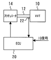
図1は、本実施の形態のシステム構成を説明するための全体構成図を示している。この図に示すように、本実施の形態のシステムは、可変動弁機構(VVT)10を備えている。可変動弁機構10は、例えば、後述する制御軸12の回転角に応じて、ロッカーアーム(図示せず)の揺動量や揺動タイミングを変化させて、リフト量、作用角、バルブタイミングといったバルブの開弁特性を連続的に変更できるように構成されている。具体的には、本実施の形態における可変動弁機構10は、例えば、特開2007−262965号公報等に記載されているような公知の技術を用いて構成されている。
[Configuration of Embodiment 1]
FIG. 1 shows an overall configuration diagram for explaining a system configuration of the present embodiment. As shown in this figure, the system of the present embodiment includes a variable valve mechanism (VVT) 10. For example, the
また、図1に示すとおり、本実施の形態の可変動弁機構10は、制御軸12を備えている。制御軸12は、バルブ反力等によって小リフト方向に付勢されている。また、可変動弁機構10には、制御軸12を任意の角度に回転駆動するためのモータ14が付設されている。モータ14は、固有のコギングトルクを有するモータとして構成されている。また、制御軸12には、該制御軸の回転角を検知するための回転角センサ22が設けられている。
Further, as shown in FIG. 1, the
また、本実施の形態のシステムは、その制御装置として、ECU(Electronic Control Unit)20が備えられている。ECU20は、内燃機関の運転状態などに基づいて、最適なリフト量を特定する他、当該リフト量を実現するためのモータ14の回転角制御等を実行する。
Further, the system of the present embodiment includes an ECU (Electronic Control Unit) 20 as its control device. The
[実施の形態1における動作]
(コギングトルクについて)
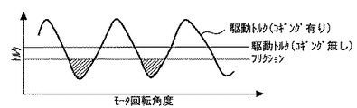
モータ14の駆動トルクにはコギングトルクが含まれている。より具体的には、コギングトルクは、モータ内の電機子と回転子との磁気的吸引力が回転角度に依存して細かく脈動することにより発生するトルクである。図2は、モータの回転角度とトルクとの関係を示す図である。この図に示すとおり、コギングトルクを含む駆動トルクは、回転角度に依存して上下に脈動している。ここで、図2に示すとおり、モータ14や可変動弁機構10におけるフリクションによるトルクが発生していると仮定すると、駆動トルクがフリクショントルクよりも小さい角度域では、モータ14の回転軸、すなわち制御軸12を保持することができることとなる。
[Operation in Embodiment 1]
(About cogging torque)
The driving torque of the
(機関停止時のVVT制御)
次に、機関停止時のVVT制御について説明する。内燃機関の運転中においては、所望のリフト量が実現されるように、制御軸12の回転角が、例えば100°〜260°の範囲で制御されている。ここで、内燃機関を停止する場合には、次回の始動時に備えて、始動性の良好な回転角度(例えば、200°)に設定しておくことが好ましい。そこで、本実施の形態のシステムでは、内燃機関のIGがオフにされる場合に、モータ14を駆動して、制御軸12を所定の回転角度に回転させることとしている。
(VVT control when the engine is stopped)
Next, VVT control when the engine is stopped will be described. During operation of the internal combustion engine, the rotation angle of the
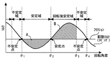
しかしながら、内燃機関の停止時に制御軸12を所定の回転角度に回転させたとしても、モータ14への通電をオフにした場合に、当該回転角度を保持できるとは限らない。図3は、モータ14への通電をオフにした場合のモータの回転角度と駆動トルクとの関係を説明するための図である。尚、この図において、θ1およびθ4は制御軸12の位置ずれを助長する方向にコギングトルクが作用する不安定点を、θ2は制御軸12の位置ずれを妨げる方向にコギングトルクが作用する安定点を、それぞれ示している。また、θ3は、図3中のAの面積、つまり、θ1〜θ2間に制御軸12に作用するトルクの積分値と、Bの面積、つまり、θ2〜θ3間に制御軸12に作用するトルクの積分値とが等しくなる回転角度を示している。
However, even if the
この図に示すとおり、モータ回転角度がθ1〜θ2の角度域では、フリクションによるトルクがコギングトルクよりも大きくなっている。このため、かかる角度域においてモータ14への通電がオフにされた場合には、制御軸12は回転されずにその回転角度で停止することができる。以下、この角度域を「安定域」と称する。
As shown in this figure, in the angle range of the motor rotation angle θ1 to θ2, the torque due to friction is larger than the cogging torque. For this reason, when the energization to the
一方、回転角度がθ2〜θ3の角度域については、コギングトルクがフリクションによるトルクよりも大きくなっている。ここで、上述したとおり、θ3は、θ2〜θ3の制御軸12のトルク積分値が、安定域におけるそれと同等となる回転角度を示している。したがって、かかる角度域においてモータ14への通電がオフにされた場合には、制御軸12は、安定点であるθ2の方向に回転して安定域内で停止する。以下、この角度域を「回転後安定域」と称する。
On the other hand, the cogging torque is larger than the torque due to the friction in the angular range where the rotation angle is θ2 to θ3. Here, as described above, θ3 represents a rotation angle at which the torque integral value of the
更に、回転角度がθ3〜θ4の角度域については、条件付安定域と同様に、コギングトルクがフリクションによるトルクよりも大きくなっている。かかる角度域においてモータ14への通電がオフにされた場合には、制御軸12は、安定点であるθ2の方向に回転する。しかしながら、かかる角度域から回転した制御軸12は、安定域で停止せずに小リフト方向に回転し続けてしまう。以下、この角度域を「不安定域」と称する。
Further, in the angular range where the rotation angle is θ3 to θ4, the cogging torque is larger than the torque due to the friction as in the conditional stability range. When the energization to the
このように、内燃機関の停止時における制御軸12の回転角度が、安定域、回転後安定域、および不安定域の何れに属しているかによって、モータ14への通電をオフにした場合の制御軸12の保持特性が異なることとなる。そこで、本実施の形態では、内燃機関の停止時における制御軸12の回転角度が、安定域または回転後安定域に属するように、該制御軸12の回転角度を制御することとする。
As described above, the control when the power supply to the
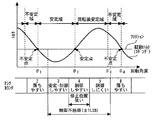
図4は、モータ14の回転角度とセンサカウンタとの関係を示す図である。この図に示すとおり、制御軸12の回転角度は、回転角センサ22によって検出されるセンサカウンタに基づいて制御される。このため、制御軸12の回転角度は、各カウンタの角度域(例えば3.75°)の幅をもって制御されることとなる。更に、この図に示すとおり、制御不感帯を考慮すると、狙いのセンサカウンタから前後1つ程度ずれることを考慮する必要がある。
FIG. 4 is a diagram showing the relationship between the rotation angle of the
そこで、本実施の形態では、制御軸12を停止可能な角度域、すなわち、安定域と回転後安定域とで構成される角度域の中間部に位置するセンサカウンタを停止位置の狙いとして設定することとする。これにより、制御不感帯を考慮したとしても、停止位置の大半を安定域或いは回転後安定域にすることができる。
Therefore, in the present embodiment, a sensor counter that is located in the middle of the angle range where the
(実施の形態1の具体的処理)
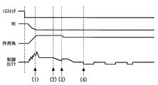
次に、図5を参照して、内燃機関の停止時におけるVVT制御の具体的処理について説明する。図5は、内燃機関の停止時のVVT動作を示すタイミングチャートである。先ず、この図の(1)に示すとおり、IGがオフとされると、モータ14のデューティ値を制御して、制御軸12を所定のセンサカウンタまで回転させる処理が実行される。所定のセンサカウンタは、上述したように、安定域と回転後安定域とで構成される角度域の中間部に位置するセンサカウンタが設定される。尚、制御軸12の回転角度を制御する場合においては、設定されたセンサカウンタか、或いはこれより1つ手前のセンサカウンタになることが多い。このため、ここでは、大リフト方向へ制御軸12を回転させて所定のセンサカウンタを実現することが好ましい。これにより、制御軸12が1つ手前のセンサカウンタで停止したとしても、安定域に停止させることができる。
(Specific processing of Embodiment 1)
Next, a specific process of VVT control when the internal combustion engine is stopped will be described with reference to FIG. FIG. 5 is a timing chart showing the VVT operation when the internal combustion engine is stopped. First, as shown in (1) of this figure, when the IG is turned off, the duty value of the
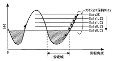
次に、この図の(2)に示すとおり、制御軸12が所定のセンサカウンタで停止した後は、モータ14の駆動トルク(保持トルク)を徐々に小さくするために、デューティ値を徐変する処理が実行される。図6はコギングトルクと保持トルクとの関係を説明するための図である。デューティ値をいきなり0%へ変化させると、保持トルクとフリクションとの差が大きいため、制御軸12の回転を加速させる原因となる。そこで、この図に示すとおり、デューティ値を例えば、2%から徐々に低下させることとする。これにより、制御軸12が徐々に回転することとなるため、確実に安定域で停止させることができる。
Next, as shown in (2) of this figure, after the
また、この図の(3)に示すとおり、上記デューティ値の徐変制御を実行中に、制御軸12が必要以上に回転し始めた場合には、デューティ値を一時的に増大させることが好ましい。これにより、制御軸12が不安定域へ回転してしまう事態を効果的に回避することが可能となる。
Further, as shown in (3) of this figure, it is preferable to temporarily increase the duty value when the
上記処理によってデューティ値が0にされると、制御軸12は安定域で停止する。しかしながら、場合によっては、制御軸12が不安定域や回転後安定域の途中で停止していることも考えられる。そこで、この図の(4)に示すとおり、ここでは、モータ14へ一時的にマイナスデューティをかけることとする。これにより、制御軸12が不安定な位置に停止していた場合に、該制御軸12を安定域へ回転させて停止させることができる。また、制御軸12は、バルブ反力等によって小リフト側に付勢されている。このため、マイナスデューティをかけて小リフト側に駆動トルクを付勢することにより、小さな駆動トルクで制御軸12を安定域まで回転させることができる。尚、この図に示すとおり、マイナスデューティ処理は、小さなマイナスデューティを複数回かけることが好ましい。
When the duty value is set to 0 by the above processing, the
以上説明した通り、本実施の形態のシステムによれば、内燃機関を停止する際に、モータ14のコギングトルクを利用して、制御軸12を所定の回転角度域で停止させることができる。これにより、次回始動時の始動性を確保することができる。
As described above, according to the system of the present embodiment, when the internal combustion engine is stopped, the
尚、上述した実施の形態1においては、可変動弁機構10が前記第1の発明における「可変動弁装置」に、モータ14が前記第1の発明における「アクチュエータ」に、それぞれ相当している。
In the first embodiment described above, the
実施の形態2.
[実施の形態2の特徴]
上述した実施の形態1において、モータ14のコギングトルクを大きくすると、コギングトルクの谷側、すなわち安定域における安定性を向上させることができる。しかしながら、その一方において、コギングトルクが大きいと、可変動弁機構10の可変モードにおいて、制御軸12の回転トルクに脈動が重畳してトルクが安定しない問題が生じる。つまり、制御軸12の回転角度によって、同一のデューティ値でも回転トルクが異なることとなるため、制御軸12の締め込み位置やたわみ量にバラツキが発生してしまうおそれがある。
[Features of Embodiment 2]
In the first embodiment described above, when the cogging torque of the
そこで、本実施の形態では、コギングトルクの脈動を抑制するように、制御デューティ値の学習を実行することとする。図8は、コギングトルクと学習時の制御デューティ値との関係を説明するための図である。この図に示すとおり、コギングトルク脈動が平滑化されるように、学習時のデューティ値(学習デューティ値)を変化させることとする。これにより、モータ14の出力としての回転トルクを一定に制御することができる。
Therefore, in the present embodiment, learning of the control duty value is executed so as to suppress the pulsation of the cogging torque. FIG. 8 is a diagram for explaining the relationship between the cogging torque and the control duty value during learning. As shown in this figure, the learning duty value (learning duty value) is changed so that the cogging torque pulsation is smoothed. Thereby, the rotational torque as the output of the
実施の形態3.
[実施の形態3の特徴]
上述した実施の形態1において、モータ14のコギングトルクを大きくすると、コギングトルクの谷側、すなわち安定域における安定性を向上させることができる。しかしながら、その一方において、コギングトルクが大きいと、コギングの山側における保持デューティ値が大きくなってしまう。特に、可変動弁機構10が可変モードに入る前の内燃機関の始動時(アイドリング時)においては、制御軸12が所定の大リフト側の回転角度(例えば240°)で保持される。このため、かかる回転角度がコギングトルクの山側に位置してしまうと、保持デューティ値が大きいことによる消費電力の増大や電磁音の増大が問題となってしまう。
[Features of Embodiment 3]
In the first embodiment described above, when the cogging torque of the
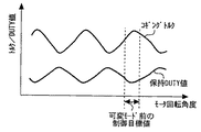
そこで、本実施の形態では、アイドリング時の制御軸12(モータ14)の回転角度がコギングトルクの谷側に位置するように、原点学習を実行することとする。図7は、制御軸12の回転角度とコギングトルクとの関係を説明するための図である。この図に示すとおり、コギングトルクの山側では保持デューティ値が増大し、谷側では減少する。そこで、この図に示すとおり、アイドリング時の制御軸12の回転角度がコギングトルクの谷側となるように、モータ14の回転角度と制御軸12の回転角度との相対位相を調整することとする。これにより、保持デューティ値を低減することができるので、消費電力や電磁音の増大を効果的に抑止することができる。
Therefore, in the present embodiment, the origin learning is performed so that the rotation angle of the control shaft 12 (motor 14) during idling is positioned on the valley side of the cogging torque. FIG. 7 is a diagram for explaining the relationship between the rotation angle of the
10 可変動弁機構
12 制御軸
14 モータ
20 ECU(Electronic Control Unit)
22 回転角センサ
10
22 Rotation angle sensor
Claims (7)
前記バルブに作用するバルブ反力で、前記制御軸をリフト減少方向へ付勢するバルブ反力付勢機構と、
前記制御軸を所定の回転角度域へ回転させるアクチュエータと、
前記内燃機関の停止時に、前記アクチュエータを駆動して前記制御軸を所定の回転角度域へ回転させる停止時制御手段と、を備え、
前記制御軸に付勢される前記アクチュエータの駆動トルクは、前記制御軸の回転角度に応じて脈動するコギングトルクを含み、
前記停止時制御手段は、前記コギングトルクの付勢方向が該制御軸の回転方向から反対方向へ切り替わる位置(以下、安定位置)を含む回転角度域へ前記制御軸を回転させることを特徴とする内燃機関の制御装置。 A control shaft for variably setting a lift amount of a valve of the internal combustion engine; the lift amount is increased by rotating the control shaft in a lift increasing direction; and the control shaft is rotated in a lift decreasing direction. A variable valve system in which the lift amount is reduced by
A valve reaction force urging mechanism for urging the control shaft in a lift decreasing direction with a valve reaction force acting on the valve;
An actuator for rotating the control shaft to a predetermined rotation angle range;
A stop-time control means for driving the actuator to rotate the control shaft to a predetermined rotation angle range when the internal combustion engine is stopped,
The drive torque of the actuator biased to the control shaft includes cogging torque that pulsates according to the rotation angle of the control shaft,
The stop-time control means rotates the control shaft to a rotation angle range including a position where the energizing direction of the cogging torque switches from the rotation direction of the control shaft to the opposite direction (hereinafter referred to as a stable position). Control device for internal combustion engine.
Priority Applications (1)
| Application Number | Priority Date | Filing Date | Title |
|---|---|---|---|
| JP2008321947A JP2010144596A (en) | 2008-12-18 | 2008-12-18 | Control device for of internal combustion engine |
Applications Claiming Priority (1)
| Application Number | Priority Date | Filing Date | Title |
|---|---|---|---|
| JP2008321947A JP2010144596A (en) | 2008-12-18 | 2008-12-18 | Control device for of internal combustion engine |
Publications (1)
| Publication Number | Publication Date |
|---|---|
| JP2010144596A true JP2010144596A (en) | 2010-07-01 |
Family
ID=42565284
Family Applications (1)
| Application Number | Title | Priority Date | Filing Date |
|---|---|---|---|
| JP2008321947A Withdrawn JP2010144596A (en) | 2008-12-18 | 2008-12-18 | Control device for of internal combustion engine |
Country Status (1)
| Country | Link |
|---|---|
| JP (1) | JP2010144596A (en) |
Cited By (3)
| Publication number | Priority date | Publication date | Assignee | Title |
|---|---|---|---|---|
| WO2014178118A1 (en) * | 2013-04-30 | 2014-11-06 | トヨタ自動車株式会社 | Vehicle control device |
| JP2017175777A (en) * | 2016-03-23 | 2017-09-28 | 株式会社デンソー | Electronic controller |
| CN112740536A (en) * | 2018-09-07 | 2021-04-30 | 贝利莫控股公司 | Actuator having motor and method of controlling motor to maintain current position |
-
2008
- 2008-12-18 JP JP2008321947A patent/JP2010144596A/en not_active Withdrawn
Cited By (8)
| Publication number | Priority date | Publication date | Assignee | Title |
|---|---|---|---|---|
| WO2014178118A1 (en) * | 2013-04-30 | 2014-11-06 | トヨタ自動車株式会社 | Vehicle control device |
| KR20150138292A (en) * | 2013-04-30 | 2015-12-09 | 도요타지도샤가부시키가이샤 | Vehicle control device |
| CN105209308A (en) * | 2013-04-30 | 2015-12-30 | 丰田自动车株式会社 | Vehicle control device |
| JP6028855B2 (en) * | 2013-04-30 | 2016-11-24 | トヨタ自動車株式会社 | Vehicle control device |
| KR101682326B1 (en) | 2013-04-30 | 2016-12-05 | 도요타지도샤가부시키가이샤 | Vehicle control device |
| US10208815B2 (en) | 2013-04-30 | 2019-02-19 | Toyota Jidosha Kabushiki Kaisha | Vehicle control device |
| JP2017175777A (en) * | 2016-03-23 | 2017-09-28 | 株式会社デンソー | Electronic controller |
| CN112740536A (en) * | 2018-09-07 | 2021-04-30 | 贝利莫控股公司 | Actuator having motor and method of controlling motor to maintain current position |
Similar Documents
| Publication | Publication Date | Title |
|---|---|---|
| CN101631933B (en) | Valve timing adjustment device | |
| US7377245B2 (en) | Valve timing controller | |
| JP2000041372A (en) | Dc torque motor, drive controller using the same, and throttle valve controller | |
| JP6090178B2 (en) | Valve timing adjustment device | |
| JP2010144596A (en) | Control device for of internal combustion engine | |
| CN102770647B (en) | Control apparatus for variable operation angle mechanism | |
| JP5598444B2 (en) | Electric valve timing variable device | |
| JP4888160B2 (en) | Variable valve operating device for internal combustion engine | |
| JP5907008B2 (en) | Valve timing adjustment device | |
| JP5104983B2 (en) | Valve timing adjustment device | |
| JP6459886B2 (en) | Electric valve timing control device | |
| JP3181862B2 (en) | Step motor drive throttle control device | |
| JP3241661B2 (en) | Method and apparatus for controlling intake throttle valve of diesel engine | |
| JPH11206092A (en) | Torque motor | |
| JP4591366B2 (en) | Control device for rotating linear motion conversion mechanism of internal combustion engine | |
| JP2011205778A (en) | Brushless motor and motor with brush | |
| JP6436056B2 (en) | Engine control device | |
| JP2007288947A (en) | Drive device and variable valve operating device for internal combustion engine equipped with the drive device | |
| JP4606473B2 (en) | Valve timing control device for internal combustion engine, controller for the valve timing control device, and controller used for valve timing changing mechanism | |
| JP2008199693A (en) | Variable valve operating device for internal combustion engine | |
| JP2008215313A (en) | Valve timing adjustment device | |
| JP4212048B2 (en) | Valve lift adjustment device | |
| JP2007162479A (en) | Valve characteristic control device for internal combustion engine | |
| JP2009215936A (en) | Control system for variable valve train | |
| JP2005299466A (en) | Valve lift adjustment device |
Legal Events
| Date | Code | Title | Description |
|---|---|---|---|
| A621 | Written request for application examination |
Effective date: 20110629 Free format text: JAPANESE INTERMEDIATE CODE: A621 |
|
| A761 | Written withdrawal of application |
Effective date: 20120125 Free format text: JAPANESE INTERMEDIATE CODE: A761 |