JP2010144599A - Vehicle control device - Google Patents
Vehicle control device Download PDFInfo
- Publication number
- JP2010144599A JP2010144599A JP2008321995A JP2008321995A JP2010144599A JP 2010144599 A JP2010144599 A JP 2010144599A JP 2008321995 A JP2008321995 A JP 2008321995A JP 2008321995 A JP2008321995 A JP 2008321995A JP 2010144599 A JP2010144599 A JP 2010144599A
- Authority
- JP
- Japan
- Prior art keywords
- engine
- integrated value
- fuel
- clutch
- engine speed
- Prior art date
- Legal status (The legal status is an assumption and is not a legal conclusion. Google has not performed a legal analysis and makes no representation as to the accuracy of the status listed.)
- Granted
Links
- 239000000446 fuel Substances 0.000 claims abstract description 77
- 230000005540 biological transmission Effects 0.000 claims abstract description 24
- 238000004364 calculation method Methods 0.000 claims abstract description 10
- 238000000034 method Methods 0.000 claims description 12
- 230000007246 mechanism Effects 0.000 claims description 11
- 230000008569 process Effects 0.000 claims description 9
- 230000001052 transient effect Effects 0.000 claims description 6
- 239000003921 oil Substances 0.000 abstract description 12
- 239000010720 hydraulic oil Substances 0.000 abstract description 9
- 230000010354 integration Effects 0.000 description 12
- 238000002347 injection Methods 0.000 description 7
- 239000007924 injection Substances 0.000 description 7
- 238000010586 diagram Methods 0.000 description 4
- 230000008859 change Effects 0.000 description 2
- 230000006837 decompression Effects 0.000 description 2
- 230000003247 decreasing effect Effects 0.000 description 2
- 238000002485 combustion reaction Methods 0.000 description 1
- 239000000498 cooling water Substances 0.000 description 1
- 238000007599 discharging Methods 0.000 description 1
- 238000002474 experimental method Methods 0.000 description 1
- 238000012986 modification Methods 0.000 description 1
- 230000004048 modification Effects 0.000 description 1
- 230000007935 neutral effect Effects 0.000 description 1
- 238000004088 simulation Methods 0.000 description 1
- 239000007858 starting material Substances 0.000 description 1
- 230000007704 transition Effects 0.000 description 1
- 238000004804 winding Methods 0.000 description 1
Images
Landscapes
- Combined Controls Of Internal Combustion Engines (AREA)
Abstract
【課題】燃料性状の判定精度を向上させる。
【解決手段】エンジンと無段変速機との間のインプットクラッチには、エンジン駆動されるオイルポンプから直に作動油が供給される。このため、エンジン停止時にはインプットクラッチが解放され、エンジン運転時にはインプットクラッチが締結される。エンジンの始動動作が開始されるとインプットクラッチの作動状態が判定され、インプットクラッチが解放状態または締結状態である場合には点火回数積算値およびエンジン回転数積算値が演算され、インプットクラッチがスリップ状態である場合には点火回数積算値およびエンジン回転数積算値の演算が中断される。そして、点火回数積算値が判定基準値Aを上回るときに、エンジン回転数積算値が判定基準値Bを上回る場合には軽質燃料であると判定され、エンジン回転数積算値が判定基準値Bを下回る場合には重質燃料であると判定される。
【選択図】図3A fuel property determination accuracy is improved.
Hydraulic oil is directly supplied to an input clutch between the engine and the continuously variable transmission from an oil pump driven by the engine. Therefore, the input clutch is released when the engine is stopped, and the input clutch is engaged when the engine is operating. When the engine start operation is started, the operating state of the input clutch is determined. If the input clutch is in the released state or the engaged state, the ignition number integrated value and the engine speed integrated value are calculated, and the input clutch is in the slip state. In this case, the calculation of the ignition number integrated value and the engine speed integrated value is interrupted. When the ignition number integrated value exceeds the determination reference value A, it is determined that the fuel is light if the engine speed integrated value exceeds the determination reference value B. If it falls below, it is determined that the fuel is heavy.
[Selection] Figure 3
Description
本発明は、エンジンと変速機構との間にクラッチ手段を備える車両の制御装置に関する。 The present invention relates to a vehicle control device including a clutch unit between an engine and a transmission mechanism.
自動車等のエンジンに供給される燃料の揮発性は、燃料の仕向地等によって変更されることが一般的となっている。例えば、低温環境となる地域に対しては揮発性の高い燃料が出荷される一方、高温環境となる地域に対しては揮発性の低い燃料が出荷されている。また、燃料の揮発性はエンジンの始動性や出力トルクを左右する要因となるため、燃料の揮発性に応じて燃料噴射量や点火時期を制御することが重要となっている。そこで、揮発性の高低(燃料性状)を判定する判定機能を組み込み、燃料性状に応じて燃料噴射量や点火時期を制御するようにした車両が提案されている(例えば、特許文献1参照)。また、エンジンのデコンプ機能を備えるハイブリッド車両においては、エンジンの不安定な燃焼状態を回避するため、燃料の揮発性が低いと判定された場合には、エンジンのデコンプ動作を中止するようにした技術が提案されている(例えば、特許文献2参照)。
ところで、特許文献2に記載されたハイブリッド車両においては、燃料噴射量とエンジントルクとの関係から燃料性状を判定している。このように、エンジンの運転状態に基づいて燃料性状を判定することから、判定時にはエンジン負荷の大幅な変動を回避することが重要となっている。しかしながら、特許文献1や特許文献2に記載された技術にあっては、燃料性状を判定する際のタイミングを考慮していないため、判定タイミングによっては燃料性状の誤判定を招いてしまうおそれがある。
By the way, in the hybrid vehicle described in
本発明の目的は、燃料性状の判定精度を向上させることにある。 An object of the present invention is to improve the determination accuracy of fuel properties.
本発明の車両の制御装置は、エンジンと変速機構との間にクラッチ手段を備える車両の制御装置であって、前記クラッチ手段の作動状態を判定するクラッチ判定手段と、前記エンジンに供給される燃料の性状を判定する燃料判定手段とを有し、前記燃料判定手段は、前記クラッチ手段が解放状態から締結状態に切り換えられる過程の過渡状態であると判定されたときに、燃料性状の判定を中断することを特徴とする。 The vehicle control device according to the present invention is a vehicle control device including a clutch unit between an engine and a transmission mechanism, and includes a clutch determination unit that determines an operating state of the clutch unit, and a fuel supplied to the engine. The fuel determination means interrupts the determination of the fuel property when it is determined that the clutch means is in a transient state in the process of switching from the released state to the engaged state. It is characterized by doing.
本発明の車両の制御装置は、前記エンジンの点火回数を積算して点火回数積算値を演算する点火回数演算手段と、前記エンジンのエンジン回転数を積算してエンジン回転数積算値を演算するエンジン回転数演算手段とを有し、前記燃料判定手段は、前記エンジンの始動動作を開始してから所定の点火回数積算値に達するまでのエンジン回転数積算値に基づいて燃料性状を判定することを特徴とする。 The vehicle control device according to the present invention includes an ignition number calculating means for calculating an integrated number of times of ignition by integrating the number of ignitions of the engine, and an engine for calculating an integrated value of the engine speed by integrating the engine speed of the engine. An engine speed calculating means, wherein the fuel determining means determines the fuel property based on the engine speed integrated value from when the engine start operation is started until the predetermined ignition frequency integrated value is reached. Features.
本発明の車両の制御装置は、前記点火回数演算手段および前記エンジン回転数演算手段は、前記クラッチ手段が過渡状態であると判定されたときに、前記点火回数積算値および前記エンジン回転数積算値の演算を中断することを特徴とする。 In the vehicle control apparatus according to the present invention, the ignition number calculating means and the engine speed calculating means are configured such that the ignition number integrated value and the engine speed integrated value are determined when the clutch means is determined to be in a transient state. The operation is interrupted.
本発明によれば、解放状態から締結状態に切り換えられるクラッチ手段の過渡状態においては、燃料性状の判定を中断するようにしたので、判定時におけるエンジン負荷の変動を抑制することができ、燃料性状の判定精度を向上させることが可能となる。 According to the present invention, in the transition state of the clutch means that is switched from the released state to the engaged state, the determination of the fuel property is interrupted, so that the fluctuation of the engine load at the time of determination can be suppressed, and the fuel property It is possible to improve the determination accuracy.
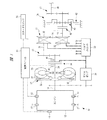
以下、本発明の実施の形態を図面に基づいて詳細に説明する。図1は車両に搭載されるパワーユニット10を示す概略図である。図1に示すように、パワーユニット10にはベルト式の無段変速機(変速機構)11が設けられている。また、エンジン12と無段変速機11との間には、トルクコンバータ13、インプットクラッチ(クラッチ手段)14および歯車列15が設けられている。エンジン12から出力されるエンジン動力は、トルクコンバータ13、インプットクラッチ14および歯車列15を介して無段変速機11に入力される。また、無段変速機11の出力側には前後進切換機構16が設けられており、無段変速機11を経たエンジン動力は前後進切換機構16によって回転方向が制御された後に、歯車列17から出力軸18を経て図示しない駆動輪に伝達される。さらに、無段変速機11等に作動油を供給するため、エンジン動力によって駆動されるオイルポンプ19が設けられるとともに、オイルポンプ19からの作動油を供給制御するバルブユニット20が設けられている。
Hereinafter, embodiments of the present invention will be described in detail with reference to the drawings. FIG. 1 is a schematic view showing a
トルクコンバータ13は、クランク軸21にフロントカバー22を介して連結されるポンプインペラ23と、このポンプインペラ23に対向するとともにタービン軸24に連結されるタービンランナ25とを備えている。トルクコンバータ13内には作動油が供給されており、ポンプインペラ23からタービンランナ25には作動油を介してエンジン動力が伝達される。また、トルクコンバータ13内には、クランク軸21とタービン軸24とを直結するロックアップクラッチ26が設けられている。
The
無段変速機11は、プライマリプーリ30を備えるプライマリ軸31と、セカンダリプーリ32を備えるセカンダリ軸33とを有している。プライマリプーリ30には図示しないプライマリ室が区画されており、このプライマリ室内の油圧を調整することによってプライマリプーリ30のシーブ幅を変化させることが可能となる。また、セカンダリプーリ32には図示しないセカンダリ室が区画されており、このセカンダリ室内の油圧を調整することによってセカンダリプーリ32のシーブ幅を変化させることが可能となる。これらのプーリ30,32には駆動ベルト34が巻き掛けられており、シーブ幅を変化させて駆動ベルト34の巻き付け径を変化させることにより、プライマリ軸31からセカンダリ軸33に対する無段変速が可能となっている。
The continuously variable transmission 11 includes a
インプットクラッチ14には図示しないクラッチ圧室が区画されている。このクラッチ圧室に対して作動油を供給することにより、インプットクラッチ14はタービン軸24と歯車列15とを連結する締結状態に切り換えられる。一方、クラッチ圧室から作動油を排出することにより、インプットクラッチ14はタービン軸24と歯車列15とを切り離す解放状態に切り換えられる。このインプットクラッチ14のクラッチ圧室には、エンジン12に駆動されるオイルポンプ19からの作動油が直に供給されるため、オイルポンプ19が停止するエンジン停止時にはインプットクラッチ14が解放状態となる一方、オイルポンプ19が駆動されるエンジン運転時にはインプットクラッチ14が締結状態となる。このインプットクラッチ14を組み込むことにより、駆動ベルト34の滑りを防止して無段変速機11を保護することが可能となる。すなわち、オイルポンプ19の吐出圧が十分に上昇していないエンジン始動直後には、プライマリ室やセカンダリ室に供給される油圧も低下していることから、プライマリプーリ30やセカンダリプーリ32のクランプ力も低下した状態となっている。このようなクランプ力の低下は駆動ベルト34の滑りを招くことになるが、エンジン始動直後においてはインプットクラッチ14が解放状態となることから、無段変速機11に対して過大なエンジントルクが入力されることは無く、駆動ベルト34の滑りを防止して無段変速機11を保護することが可能となっている。
The input clutch 14 has a clutch pressure chamber (not shown). By supplying hydraulic oil to the clutch pressure chamber, the input clutch 14 is switched to an engaged state in which the
前後進切換機構16は、遊星歯車列40、前進クラッチ41および後退ブレーキ42を備えている。これら前進クラッチ41や後退ブレーキ42を制御することにより、出力軸18の回転方向を切り換えることが可能となっている。後退ブレーキ42を開放して前進クラッチ41を締結することにより、セカンダリ軸33が歯車列17に対して直に連結されるため、出力軸18を正転方向に回転させて車両を前進走行させることが可能となる。また、前進クラッチ41を開放して後退ブレーキ42を締結することにより、セカンダリ軸33が遊星歯車列40を介して歯車列17に連結されるため、出力軸18を逆転方向に回転させて車両を後退走行させることが可能となる。なお、前進クラッチ41および後退ブレーキ42を開放することにより、前後進切換機構16は出力軸18にエンジン動力を伝達しないニュートラル状態となる。
The forward /
また、エンジン12や無段変速機11等を制御するため、パワーユニット10には制御ユニット43が接続されている。制御ユニット43には各種センサから車両状態を示す信号が入力されており、これらの入力信号に基づいて制御ユニット43はエンジン12や無段変速機11等に対して制御信号を出力する。さらに、制御ユニット43は、エンジン始動時に燃料の性状(揮発性の高低)を判定する判定機能を有しており、判定された燃料性状に基づいてエンジン制御における燃料噴射量や点火時期を補正することが可能となっている。燃料性状を判定するため、制御ユニット43には、エンジン回転数Neを検出するクランク角センサ44、インプットクラッチ14の入力側回転数Niを検出する入力側回転センサ45、インプットクラッチ14の出力側回転数Noを検出する出力側回転センサ46等が接続されている。
In addition, a
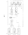
以下、制御ユニット43によってエンジン始動時に実行される燃料性状の判定制御について説明する。ここで、図2は本発明の一実施の形態である制御装置として機能する制御ユニット43の一部を示すブロック図である。図2に示すように、制御ユニット43は、クラッチ判定部50、点火回数積算部51、タイミング判定部52、エンジン回転数積算部53、燃料性状判定部54、判定フラグ設定部55を備えている。スタータスイッチ56のオン操作に伴ってエンジン12の始動動作が開始されると、クラッチ判定手段としてのクラッチ判定部50は、入力側回転数Niおよび出力側回転数Noに基づいてインプットクラッチ14の作動状態を判定する。すなわち、クラッチ判定部50は、出力側回転数Noが0(停止状態)である場合にはインプットクラッチ14が解放状態であると判定し、出力側回転数Noの増加が検出された場合にはインプットクラッチ14がスリップ状態(過渡状態)であると判定し、入力側回転数Niと出力側回転数Noとの回転差が0になった場合にはインプットクラッチ14が締結状態であると判定する。そして、クラッチ判定部50は、インプットクラッチ14の作動状態(解放状態,スリップ状態,締結状態)を点火回数積算部51およびエンジン回転数積算部53に出力する。
Hereinafter, fuel property determination control executed by the
インプットクラッチ14が解放状態または締結状態である場合に、点火回数演算手段としての点火回数積算部51は、点火プラグ57の点火回数Nigを積算して点火回数積算値ΣNigを演算する。同様に、インプットクラッチ14が解放状態または締結状態である場合に、エンジン回転数演算手段としてのエンジン回転数積算部53は、エンジン回転数Neを積算してエンジン回転数積算値ΣNeを演算する。一方、インプットクラッチ14が解放状態から締結状態に切り換えられる過程のスリップ状態である場合には、点火回数積算部51は点火回数積算値ΣNigの演算を中断し、エンジン回転数積算部53はエンジン回転数積算値ΣNeの演算を中断する。すなわち、インプットクラッチ14が解放状態または締結状態である場合にのみ、点火回数積算値ΣNigやエンジン回転数積算値ΣNeが積算されることになる。
When the input clutch 14 is in the disengaged state or the engaged state, the ignition
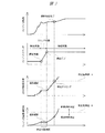
ここで、図3はエンジン12の始動動作が開始された後の各種データの変動状況を示す線図であり、図3にはエンジン回転数Ne、インプットクラッチ14の作動状態、点火回数積算値ΣNigおよびエンジン回転数積算値ΣNeの変動状況が示されている。図3に示すように、エンジン12の始動動作が開始されてインプットクラッチ14の解放状態が終了するまでは、点火回数積算値ΣNigおよびエンジン回転数積算値ΣNeが演算される。続いて、インプットクラッチ14がスリップ状態となると、点火回数積算値ΣNigおよびエンジン回転数積算値ΣNeの演算は中断され、点火回数積算値ΣNigおよびエンジン回転数積算値ΣNeの数値が保持される。そして、インプットクラッチ14が締結状態に切り換えられると、点火回数積算値ΣNigおよびエンジン回転数積算値ΣNeの演算が再開されることになる。
Here, FIG. 3 is a diagram showing the fluctuation state of various data after the start operation of the
図2に示すように、点火回数積算部51によって演算される点火回数積算値ΣNigは、点火回数積算部51からタイミング判定部52に入力される。このタイミング判定部52においては、点火回数積算値ΣNigが所定の判定基準値Aを上回るか否かが判定される。そして、点火回数積算値ΣNigが判定基準値Aを上回った場合には、タイミング判定部52から燃料判定手段である燃料性状判定部54に対して判定開始信号が出力される。燃料性状判定部54に判定開始信号が入力されると、燃料性状判定部54によってエンジン回転数積算値ΣNeが所定の判定基準値Bを上回るか否かが判定される。エンジン回転数積算値ΣNeが判定基準値Bを上回る場合には、エンジン回転数Neが上昇し易い傾向であることから、エンジン12に供給された燃料が揮発性の高い軽質燃料であると判定される。一方、エンジン回転数積算値ΣNeが判定基準値Bを下回る場合には、エンジン回転数Neが上昇し難い傾向であることから、エンジン12に供給された燃料が揮発性の低い重質燃料であると判定される。図3に示す場合には、点火回数積算値ΣNigが判定基準値Aを上回るときに、エンジン回転数積算値ΣNeが判定基準値Bを下回ることから、エンジン12に供給される燃料が揮発性の低い重質燃料であると判定されることになる。続いて、図2に示すように、燃料性状判定部54からの判定結果に基づいて、判定フラグ設定部55によって軽質燃料または重質燃料に対応するフラグが設定され、判定された燃料性状がエンジン12の燃料噴射制御や点火制御等に反映される。なお、点火回数積算値ΣNigと比較判定される判定基準値Aや、エンジン回転数積算値ΣNeと比較判定される判定基準値Bは、実験やシミュレーション等に基づいて予め設定される値であるが、判定基準値A,Bをエンジン12の冷却水温等に基づいて変化させるようにしても良い。
As shown in FIG. 2, the ignition count integrated value ΣNig calculated by the ignition
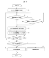
図4は燃料性状の判定制御を実行する際の手順を示すフローチャートである。図4に示すように、ステップS1においてクランキングや燃料噴射等のエンジン始動動作が開始されると、続くステップS2では、インプットクラッチ14の締結開始信号を受信したか否か、すなわちインプットクラッチ14が解放状態からスリップ状態に移行したか否かが判定される。ステップS2において、締結開始信号が受信されていないと判定された場合には、インプットクラッチ14が解放状態であるため、ステップS3に進み、点火回数積算値ΣNigが演算される。一方、ステップS2において、締結開始信号が受信されていると判定された場合には、ステップS4に進み、インプットクラッチ14の締結完了信号を受信したか否か、すなわちインプットクラッチ14がスリップ状態から締結状態に移行したか否かが判定される。ステップS4において、締結完了信号が受信されていると判定された場合には、インプットクラッチ14が締結状態であるため、ステップS3に進み、点火回数積算値ΣNigが演算される。一方、ステップS4において、締結完了信号が受信されていないと判定された場合には、インプットクラッチ14がスリップ状態であることから、インプットクラッチ14が締結状態に移行してする締結完了信号が出力されるまで、ステップS4の判定が繰り返されることになる。 FIG. 4 is a flowchart showing a procedure for executing fuel property determination control. As shown in FIG. 4, when the engine start operation such as cranking or fuel injection is started in step S1, in the subsequent step S2, whether or not the engagement start signal of the input clutch 14 is received, that is, the input clutch 14 is It is determined whether or not the release state has shifted to the slip state. If it is determined in step S2 that the engagement start signal has not been received, the input clutch 14 is in a disengaged state, and thus the process proceeds to step S3, where the ignition number integrated value ΣNig is calculated. On the other hand, if it is determined in step S2 that the engagement start signal has been received, the process proceeds to step S4 to determine whether or not the engagement completion signal for the input clutch 14 has been received, that is, the input clutch 14 has been engaged from the slip state. It is determined whether or not the state has been changed. If it is determined in step S4 that the engagement completion signal has been received, the input clutch 14 is in the engagement state, and thus the process proceeds to step S3, where the ignition number integrated value ΣNig is calculated. On the other hand, if it is determined in step S4 that the engagement completion signal has not been received, since the input clutch 14 is in the slip state, an engagement completion signal indicating that the input clutch 14 has shifted to the engagement state is output. Until this is done, the determination in step S4 is repeated.
前述したように、ステップS3において点火回数積算値ΣNigが演算されると、続くステップS5においてエンジン回転数積算値ΣNeが演算される。次いで、ステップS6では点火回数積算値ΣNigが判定基準値Aを上回るか否かが判定される。ステップS6において、点火回数積算値ΣNigが判定基準値Aを下回る場合には、燃料性状の判定タイミングに達していないことから、再びステップS2に進み、インプットクラッチ14の作動判定、点火回数積算値ΣNigの演算、エンジン回転数積算値ΣNeの演算が繰り返されることになる。一方、ステップS6において、点火回数積算値ΣNigが判定基準値Aを上回る場合には、燃料性状の判定タイミングに達していることから、ステップS7に進み、エンジン回転数積算値ΣNeが判定基準値Bを上回るか否かが判定される。そして、ステップS7において、エンジン回転数積算値ΣNeが判定基準値Bを上回る場合には、ステップS8に進み、エンジン12に供給された燃料が揮発性の高い軽質燃料であると判定される。一方、ステップS7において、エンジン回転数積算値ΣNeが判定基準値Bを下回る場合には、ステップS9に進み、エンジン12に供給された燃料が揮発性の低い重質燃料であると判定される。
As described above, when the ignition number integrated value ΣNig is calculated in step S3, the engine speed integrated value ΣNe is calculated in subsequent step S5. Next, in step S6, it is determined whether or not the ignition number integrated value ΣNig exceeds the determination reference value A. In step S6, if the ignition count integrated value ΣNig is less than the determination reference value A, the fuel property determination timing has not been reached, so the process proceeds to step S2 again to determine whether the input clutch 14 is activated and the ignition count integrated value ΣNig. And the calculation of the engine speed integrated value ΣNe are repeated. On the other hand, when the ignition number integrated value ΣNig exceeds the determination reference value A in step S6, since the fuel property determination timing has been reached, the process proceeds to step S7, where the engine speed integrated value ΣNe is determined as the determination reference value B. It is determined whether or not the value exceeds. In step S7, if the engine rotational speed integrated value ΣNe exceeds the determination reference value B, the process proceeds to step S8, where it is determined that the fuel supplied to the
これまで説明したように、インプットクラッチ14が解放状態から締結状態に移行するスリップ状態である場合には、点火回数積算値ΣNigおよびエンジン回転数積算値ΣNeの演算を中断して燃料性状の判定を行わないようにしたので、燃料性状の誤判定を回避することが可能となる。すなわち、インプットクラッチ14がスリップ状態である場合には、変化するインプットクラッチ14のトルク容量に応じてエンジン負荷が変動する状況であるため、燃料性状以外の要因によってエンジン回転数Neが左右されることになる。このようなインプットクラッチ14の過渡状態を回避しながら燃料性状を判定することにより、燃料性状の判定精度を高めることができ、エンジン12の運転状態を良好に保って車両品質を向上させることが可能となる。
As described above, when the input clutch 14 is in the slip state in which it is shifted from the released state to the engaged state, the calculation of the ignition number integrated value ΣNig and the engine speed integrated value ΣNe is interrupted to determine the fuel property. Since this is not performed, it is possible to avoid erroneous determination of fuel properties. That is, when the input clutch 14 is in the slip state, the engine load fluctuates according to the changing torque capacity of the input clutch 14, and therefore the engine speed Ne is influenced by factors other than the fuel properties. become. By determining the fuel properties while avoiding such a transient state of the input clutch 14, it is possible to improve the accuracy of determining the fuel properties, and it is possible to improve the vehicle quality while maintaining the operating state of the
本発明は前記実施の形態に限定されるものではなく、その要旨を逸脱しない範囲で種々変更可能であることはいうまでもない。たとえば、前述の説明では、揮発性の高い軽質燃料であるか、揮発性の低い重質燃料であるかについて判定しているが、これに限られることはなく、3つ以上の段階に分けて燃料性状を判定しても良い。また、前述の説明では、点火回数積算値ΣNigとエンジン回転数積算値ΣNeとに基づいて燃料性状を判定しているが、燃料噴射量やエンジントルク等に基づいて燃料性状を判定しても良い。 It goes without saying that the present invention is not limited to the above-described embodiment, and various modifications can be made without departing from the scope of the invention. For example, in the above description, it is determined whether the fuel is light fuel with high volatility or heavy fuel with low volatility, but the present invention is not limited to this, and is divided into three or more stages. The fuel property may be determined. In the above description, the fuel property is determined based on the ignition number integrated value ΣNig and the engine speed integrated value ΣNe. However, the fuel property may be determined based on the fuel injection amount, the engine torque, and the like. .
また、前述の説明では、入力側回転数Niと出力側回転数Noとに基づいてインプットクラッチ14の作動状態を判定しているが、これに限られることはなく、オイルポンプ19の回転数やオイルポンプ19の吐出圧等に基づいてインプットクラッチ14の作動状態を判定しても良い。さらに、前述の説明では、オイルポンプ19からインプットクラッチ14に対して直に作動油が供給されているが、オイルポンプ19からバルブユニット20を介して調整された作動油をインプットクラッチ14に対して供給しても良い。
In the above description, the operating state of the input clutch 14 is determined based on the input side rotational speed Ni and the output side rotational speed No. However, the present invention is not limited to this. The operating state of the input clutch 14 may be determined based on the discharge pressure of the
また、図示する場合には、オイルポンプ19がクランク軸21によってチェーン駆動されているが、これに限られることはなく、トルクコンバータ13のポンプインペラ23にオイルポンプを連結しても良い。また、摩擦クラッチをインプットクラッチ14として用いる場合には、湿式や乾式であっても良く、単板式や多板式であっても良い。さらに、摩擦クラッチだけでなく噛合クラッチをインプットクラッチ14として用いるようにしても良い。なお、変速機構としてベルト式の無段変速機11が示されているが、トロイダル式の無段変速機、遊星歯車式の自動変速機、平行軸式の自動変速機等の他の形式の変速機構を用いることも可能である。
In the illustrated case, the
11 無段変速機(変速機構)
12 エンジン
14 インプットクラッチ(クラッチ手段)
43 制御ユニット(制御装置)
50 クラッチ判定部(クラッチ判定手段)
51 点火回数積算部(点火回数演算手段)
53 エンジン回転数積算部(エンジン回転数演算手段)
54 燃料性状判定部(燃料判定手段)
Nig 点火回数
ΣNig 点火回数積算値
Ne エンジン回転数
ΣNe エンジン回転数積算値
11 continuously variable transmission (transmission mechanism)
12 Engine 14 Input clutch (clutch means)
43 Control unit (control device)
50 Clutch determination unit (clutch determination means)
51 Ignition frequency integration unit (Ignition frequency calculation means)
53 Engine speed integration unit (engine speed calculation means)
54 Fuel property determination unit (fuel determination means)
Nig Ignition frequency ΣNig Ignition frequency integration value Ne Engine speed ΣNe Engine speed integration value
Claims (3)
前記クラッチ手段の作動状態を判定するクラッチ判定手段と、
前記エンジンに供給される燃料の性状を判定する燃料判定手段とを有し、
前記燃料判定手段は、前記クラッチ手段が解放状態から締結状態に切り換えられる過程の過渡状態であると判定されたときに、燃料性状の判定を中断することを特徴とする車両の制御装置。 A vehicle control device including a clutch means between an engine and a transmission mechanism,
Clutch determining means for determining an operating state of the clutch means;
Fuel determination means for determining properties of fuel supplied to the engine;
The fuel control means interrupts the fuel property determination when it is determined that the clutch means is in a transient state in the process of switching from the released state to the engaged state.
前記エンジンの点火回数を積算して点火回数積算値を演算する点火回数演算手段と、
前記エンジンのエンジン回転数を積算してエンジン回転数積算値を演算するエンジン回転数演算手段とを有し、
前記燃料判定手段は、前記エンジンの始動動作を開始してから所定の点火回数積算値に達するまでのエンジン回転数積算値に基づいて燃料性状を判定することを特徴とする車両の制御装置。 The vehicle control device according to claim 1,
Ignition frequency calculating means for calculating the ignition frequency integrated value by integrating the engine ignition frequency;
Engine speed calculating means for calculating the engine speed integrated value by integrating the engine speed of the engine;
The vehicle control apparatus characterized in that the fuel determination means determines a fuel property based on an integrated value of the engine speed from when the engine start operation is started until a predetermined ignition frequency integrated value is reached.
前記点火回数演算手段および前記エンジン回転数演算手段は、前記クラッチ手段が過渡状態であると判定されたときに、前記点火回数積算値および前記エンジン回転数積算値の演算を中断することを特徴とする車両の制御装置。 The vehicle control device according to claim 2,
The ignition number calculating means and the engine speed calculating means interrupt the calculation of the ignition number integrated value and the engine speed integrated value when it is determined that the clutch means is in a transient state. A vehicle control device.
Priority Applications (1)
| Application Number | Priority Date | Filing Date | Title |
|---|---|---|---|
| JP2008321995A JP5295746B2 (en) | 2008-12-18 | 2008-12-18 | Vehicle control device |
Applications Claiming Priority (1)
| Application Number | Priority Date | Filing Date | Title |
|---|---|---|---|
| JP2008321995A JP5295746B2 (en) | 2008-12-18 | 2008-12-18 | Vehicle control device |
Publications (2)
| Publication Number | Publication Date |
|---|---|
| JP2010144599A true JP2010144599A (en) | 2010-07-01 |
| JP5295746B2 JP5295746B2 (en) | 2013-09-18 |
Family
ID=42565287
Family Applications (1)
| Application Number | Title | Priority Date | Filing Date |
|---|---|---|---|
| JP2008321995A Expired - Fee Related JP5295746B2 (en) | 2008-12-18 | 2008-12-18 | Vehicle control device |
Country Status (1)
| Country | Link |
|---|---|
| JP (1) | JP5295746B2 (en) |
Cited By (3)
| Publication number | Priority date | Publication date | Assignee | Title |
|---|---|---|---|---|
| RU2604642C1 (en) * | 2014-07-31 | 2016-12-10 | Тойота Дзидося Кабусики Кайся | Device of internal combustion engine fuel properties determining |
| RU2606963C1 (en) * | 2014-08-01 | 2017-01-10 | Тойота Дзидося Кабусики Кайся | Device of internal combustion engine fuel properties determining |
| US20250133999A1 (en) * | 2023-10-27 | 2025-05-01 | Cnh Industrial America Llc | System and method for determining the clutch status of an agricultural baler |
Citations (5)
| Publication number | Priority date | Publication date | Assignee | Title |
|---|---|---|---|---|
| JPH04213057A (en) * | 1990-12-10 | 1992-08-04 | Mazda Motor Corp | Fuel-property detecting apparatus |
| JPH0932607A (en) * | 1995-07-14 | 1997-02-04 | Toyota Motor Corp | Idle speed control device for internal combustion engine |
| JP2007127007A (en) * | 2005-11-02 | 2007-05-24 | Hitachi Ltd | Control device for internal combustion engine |
| JP2008163774A (en) * | 2006-12-27 | 2008-07-17 | Denso Corp | Fuel property determination device for internal combustion engine |
| JP2008215128A (en) * | 2007-03-01 | 2008-09-18 | Toyota Motor Corp | Monitoring device |
-
2008
- 2008-12-18 JP JP2008321995A patent/JP5295746B2/en not_active Expired - Fee Related
Patent Citations (5)
| Publication number | Priority date | Publication date | Assignee | Title |
|---|---|---|---|---|
| JPH04213057A (en) * | 1990-12-10 | 1992-08-04 | Mazda Motor Corp | Fuel-property detecting apparatus |
| JPH0932607A (en) * | 1995-07-14 | 1997-02-04 | Toyota Motor Corp | Idle speed control device for internal combustion engine |
| JP2007127007A (en) * | 2005-11-02 | 2007-05-24 | Hitachi Ltd | Control device for internal combustion engine |
| JP2008163774A (en) * | 2006-12-27 | 2008-07-17 | Denso Corp | Fuel property determination device for internal combustion engine |
| JP2008215128A (en) * | 2007-03-01 | 2008-09-18 | Toyota Motor Corp | Monitoring device |
Cited By (4)
| Publication number | Priority date | Publication date | Assignee | Title |
|---|---|---|---|---|
| RU2604642C1 (en) * | 2014-07-31 | 2016-12-10 | Тойота Дзидося Кабусики Кайся | Device of internal combustion engine fuel properties determining |
| RU2606963C1 (en) * | 2014-08-01 | 2017-01-10 | Тойота Дзидося Кабусики Кайся | Device of internal combustion engine fuel properties determining |
| US9541015B2 (en) | 2014-08-01 | 2017-01-10 | Toyota Jidosha Kabushiki Kaisha | Fuel property determination apparatus for internal combustion engine |
| US20250133999A1 (en) * | 2023-10-27 | 2025-05-01 | Cnh Industrial America Llc | System and method for determining the clutch status of an agricultural baler |
Also Published As
| Publication number | Publication date |
|---|---|
| JP5295746B2 (en) | 2013-09-18 |
Similar Documents
| Publication | Publication Date | Title |
|---|---|---|
| JP4358130B2 (en) | Hydraulic control device for automatic transmission | |
| US9284910B2 (en) | Vehicle control device and vehicle control method | |
| JP5790670B2 (en) | Vehicle control device | |
| JP6076146B2 (en) | Vehicle control device | |
| JP6176192B2 (en) | Vehicle control device | |
| CN104428564B (en) | The control method controlling device and vehicle of vehicle | |
| JP5295746B2 (en) | Vehicle control device | |
| JP5926299B2 (en) | Abnormality detection device for continuously variable transmission and abnormality detection method for continuously variable transmission | |
| JP6293282B2 (en) | Vehicle control apparatus and control method | |
| JP6219211B2 (en) | Control device for transmission | |
| JP6023692B2 (en) | Rotation control device for internal combustion engine | |
| JP5362936B1 (en) | Vehicle control device | |
| JP6142770B2 (en) | Vehicle control device | |
| JP5946383B2 (en) | Control device | |
| JP2014202218A (en) | Vehicle control device | |
| JP2017082986A (en) | Control device of continuously variable transmission | |
| JP6120697B2 (en) | Control device for internal combustion engine | |
| JP5295988B2 (en) | Control device for continuously variable transmission | |
| JP7139058B2 (en) | control device for continuously variable transmission | |
| JP2016130561A (en) | Control device and control method of idle stop vehicle | |
| WO2019069344A1 (en) | Vehicle control method and vehicle control device | |
| JP2018017388A (en) | Control device for vehicle | |
| JP2017032074A (en) | Control device for belt type continuously variable transmission | |
| JP2015143479A (en) | Control | |
| JP2020056433A (en) | Slip down determination device |
Legal Events
| Date | Code | Title | Description |
|---|---|---|---|
| A621 | Written request for application examination |
Free format text: JAPANESE INTERMEDIATE CODE: A621 Effective date: 20111021 |
|
| A131 | Notification of reasons for refusal |
Free format text: JAPANESE INTERMEDIATE CODE: A131 Effective date: 20120828 |
|
| A977 | Report on retrieval |
Free format text: JAPANESE INTERMEDIATE CODE: A971007 Effective date: 20120831 |
|
| A521 | Request for written amendment filed |
Free format text: JAPANESE INTERMEDIATE CODE: A523 Effective date: 20121029 |
|
| A131 | Notification of reasons for refusal |
Free format text: JAPANESE INTERMEDIATE CODE: A131 Effective date: 20121225 |
|
| A521 | Request for written amendment filed |
Free format text: JAPANESE INTERMEDIATE CODE: A523 Effective date: 20130225 |
|
| TRDD | Decision of grant or rejection written | ||
| A01 | Written decision to grant a patent or to grant a registration (utility model) |
Free format text: JAPANESE INTERMEDIATE CODE: A01 Effective date: 20130611 |
|
| A61 | First payment of annual fees (during grant procedure) |
Free format text: JAPANESE INTERMEDIATE CODE: A61 Effective date: 20130612 |
|
| R150 | Certificate of patent or registration of utility model |
Ref document number: 5295746 Country of ref document: JP Free format text: JAPANESE INTERMEDIATE CODE: R150 Free format text: JAPANESE INTERMEDIATE CODE: R150 |
|
| S531 | Written request for registration of change of domicile |
Free format text: JAPANESE INTERMEDIATE CODE: R313531 |
|
| R350 | Written notification of registration of transfer |
Free format text: JAPANESE INTERMEDIATE CODE: R350 |
|
| R250 | Receipt of annual fees |
Free format text: JAPANESE INTERMEDIATE CODE: R250 |
|
| S533 | Written request for registration of change of name |
Free format text: JAPANESE INTERMEDIATE CODE: R313533 |
|
| R350 | Written notification of registration of transfer |
Free format text: JAPANESE INTERMEDIATE CODE: R350 |
|
| R250 | Receipt of annual fees |
Free format text: JAPANESE INTERMEDIATE CODE: R250 |
|
| R250 | Receipt of annual fees |
Free format text: JAPANESE INTERMEDIATE CODE: R250 |
|
| R250 | Receipt of annual fees |
Free format text: JAPANESE INTERMEDIATE CODE: R250 |
|
| R250 | Receipt of annual fees |
Free format text: JAPANESE INTERMEDIATE CODE: R250 |
|
| R250 | Receipt of annual fees |
Free format text: JAPANESE INTERMEDIATE CODE: R250 |
|
| LAPS | Cancellation because of no payment of annual fees |