JP2010146431A - Memory control device - Google Patents
Memory control device Download PDFInfo
- Publication number
- JP2010146431A JP2010146431A JP2008324989A JP2008324989A JP2010146431A JP 2010146431 A JP2010146431 A JP 2010146431A JP 2008324989 A JP2008324989 A JP 2008324989A JP 2008324989 A JP2008324989 A JP 2008324989A JP 2010146431 A JP2010146431 A JP 2010146431A
- Authority
- JP
- Japan
- Prior art keywords
- processor
- memory
- control means
- request
- occupancy
- Prior art date
- Legal status (The legal status is an assumption and is not a legal conclusion. Google has not performed a legal analysis and makes no representation as to the accuracy of the status listed.)
- Granted
Links
- 238000000034 method Methods 0.000 claims description 18
- 239000000725 suspension Substances 0.000 claims description 2
- 230000006870 function Effects 0.000 description 11
- 238000010586 diagram Methods 0.000 description 10
- 239000000203 mixture Substances 0.000 description 2
- 230000003111 delayed effect Effects 0.000 description 1
- 230000002265 prevention Effects 0.000 description 1
- 230000004044 response Effects 0.000 description 1
- 230000001629 suppression Effects 0.000 description 1
Images


Abstract
Description
本発明は、メモリ制御装置にかかり、特に、マルチプロセッサにて共有する共有メモリを備えたメモリ制御装置に関する。 The present invention relates to a memory control device, and more particularly to a memory control device including a shared memory shared by multiple processors.
システム性能の向上を図るべく、演算処理を行うプロセッサを複数装備したシステムがある。このようなマルチプロセッサシステムでは、各プロセッサがメモリを共有して使用している。そして、プロセッサが共有メモリを使用する際には、当該プロセッサが共有メモリを占有し、排他制御(占有:ロック)を行う。すると、この間、他のプロセッサが共有メモリにアクセスしても、当該共有メモリにはアクセスすることができない。このような制御を行う技術が、特許文献1,2に開示されている。
In order to improve system performance, there are systems equipped with a plurality of processors that perform arithmetic processing. In such a multiprocessor system, the processors share the memory. When the processor uses the shared memory, the processor occupies the shared memory and performs exclusive control (occupation: lock). During this time, even if another processor accesses the shared memory, the shared memory cannot be accessed. Techniques for performing such control are disclosed in
特許文献1,2では、共有メモリ内に排他制御フラグを格納する領域を設け、共有メモリを占有しているプロセッサの情報を記憶している。そして、この排他制御フラグの格納状況に応じて、プロセッサからの共有メモリのロック要求を制御している。
In
しかしながら、上記特許文献に開示の技術では、共有メモリのロック状態を制御するために参照する排他制御フラグが共有メモリ内に存在しているため、各プロセッサは、常に共有メモリに対してロック要求を発行する必要がある。つまり、共有メモリが所定のプロセッサに占有されている場合であっても、他のプロセッサが共有メモリを占有するには、定期的に共有メモリにロック要求を発行して当該共有メモリ内の排他制御フラグを参照しなければならず、メモリロックが実行可能となるよう待ち合わせなければならない。すると、このような状態ですでに共有メモリを占有している所定のプロセッサからアンロック要求が発行された場合であっても、他のプロセッサからのロック要求と競合する。そして、このような場合に、アンロック要求が調停で負けると、ロック取得期間が延長してしまい、他のプロセッサのロック取得が遅延しうる。その結果、システム性能が低下する、という問題が生じる。 However, in the technique disclosed in the above-mentioned patent document, since the exclusive control flag to be referenced for controlling the lock state of the shared memory exists in the shared memory, each processor always issues a lock request to the shared memory. Must be issued. That is, even when the shared memory is occupied by a predetermined processor, in order for another processor to occupy the shared memory, a lock request is periodically issued to the shared memory and exclusive control within the shared memory is performed. You must refer to the flag and wait for the memory lock to be executed. Then, even when an unlock request is issued from a predetermined processor that already occupies the shared memory in such a state, it conflicts with a lock request from another processor. In such a case, if the unlock request is lost by arbitration, the lock acquisition period is extended, and the lock acquisition of other processors can be delayed. As a result, there arises a problem that the system performance is degraded.
このため、本発明の目的は、上述した課題である、マルチプロセッサにて共有メモリを共有するシステムの性能の向上を図ることができるメモリ制御を実現する、ことにある。 Therefore, an object of the present invention is to realize memory control that can improve the performance of a system that shares a shared memory among multiple processors, which is the above-described problem.
かかる目的を達成するため本発明の一形態であるメモリ制御装置は、
データを格納するメモリ領域を利用して演算処理を行う複数のプロセッサと、
当該複数のプロセッサにて共有される共有メモリと、
上記プロセッサから発行された占有要求/占有解除要求を受け付けて、上記プロセッサ毎の上記共有メモリに対する占有/占有解除を制御するメモリ制御手段と、
上記プロセッサから発行された上記共有メモリに対する占有要求/占有解除要求を上記メモリ制御手段に通知するプロセッサ制御手段と、を備え、
上記メモリ制御手段は、上記プロセッサによる上記共有メモリの占有状態を上記プロセッサ制御手段に通知し、
上記プロセッサ制御手段は、上記メモリ制御手段からの通知に基づいて上記共有メモリの占有状態を管理すると共に、当該共有メモリが所定の上記プロセッサに占有されている場合に、他の上記プロセッサから発行された上記共有メモリに対する占有要求の上記メモリ制御手段に対する通知を停止する、
という構成を採る。
In order to achieve this object, a memory control device according to one aspect of the present invention is provided.
A plurality of processors that perform arithmetic processing using a memory area for storing data;
A shared memory shared by the plurality of processors;
Memory control means for accepting an occupancy request / occupancy release request issued from the processor and controlling occupancy / occupancy release for the shared memory for each processor;
Processor control means for notifying the memory control means of an exclusive request / exclusive request for the shared memory issued by the processor,
The memory control means notifies the processor control means of the occupation state of the shared memory by the processor;
The processor control unit manages the occupation state of the shared memory based on the notification from the memory control unit, and is issued from another processor when the shared memory is occupied by a predetermined processor. Stop the notification to the memory control means of the occupation request to the shared memory,
The structure is taken.
また、本発明の他の形態であるプログラムは、
データを格納するメモリ領域を利用して演算処理を行う複数のプロセッサと、
当該複数のプロセッサにて共有される共有メモリと、
上記プロセッサから発行された占有要求/占有解除要求を受け付けて、上記プロセッサ毎の上記共有メモリに対する占有/占有解除を制御するメモリ制御手段と、
上記プロセッサから発行された上記共有メモリに対する占有要求/占有解除要求を上記メモリ制御手段に通知するプロセッサ制御手段と、
を備えたメモリ制御装置の上記プロセッサ制御手段に、
上記メモリ制御手段から通知された上記プロセッサによる上記共有メモリの占有状態に基づいて当該共有メモリの占有状態を管理すると共に、当該共有メモリが所定の上記プロセッサに占有されている場合に、他の上記プロセッサから発行された上記共有メモリに対する占有要求の上記メモリ制御手段に対する通知を停止する処理、
を実現させるためのプログラムである。
Moreover, the program which is the other form of this invention is:
A plurality of processors that perform arithmetic processing using a memory area for storing data;
A shared memory shared by the plurality of processors;
Memory control means for accepting an occupancy request / occupancy release request issued from the processor and controlling occupancy / occupancy release for the shared memory for each processor;
Processor control means for notifying the memory control means of an occupancy request / occupancy release request for the shared memory issued by the processor;
In the processor control means of the memory control device comprising:
The occupancy state of the shared memory is managed based on the occupancy state of the shared memory by the processor notified from the memory control means, and when the shared memory is occupied by a predetermined processor, the other A process for stopping notification to the memory control means of the occupation request for the shared memory issued by the processor;
It is a program for realizing.
また、本発明の他の形態であるメモリ制御方法は、
データを格納するメモリ領域を利用して演算処理を行う複数のプロセッサと、
当該複数のプロセッサにて共有される共有メモリと、
上記プロセッサから発行された占有要求/占有解除要求を受け付けて、上記プロセッサ毎の上記共有メモリに対する占有/占有解除を制御するメモリ制御手段と、
上記プロセッサから発行された上記共有メモリに対する占有要求/占有解除要求を上記メモリ制御手段に通知するプロセッサ制御手段と、を備えたメモリ制御装置にて、
上記メモリ制御手段が、上記プロセッサによる上記共有メモリの占有状態を上記プロセッサ制御手段に通知し、
上記プロセッサ制御手段が、上記メモリ制御手段からの通知に基づいて上記共有メモリの占有状態を管理すると共に、当該共有メモリが所定の上記プロセッサに占有されている場合に、他の上記プロセッサから発行された上記共有メモリに対する占有要求の上記メモリ制御手段に対する通知を停止する、
という構成を採る。
In addition, a memory control method according to another aspect of the present invention includes:
A plurality of processors that perform arithmetic processing using a memory area for storing data;
A shared memory shared by the plurality of processors;
Memory control means for accepting an occupancy request / occupancy release request issued from the processor and controlling occupancy / occupancy release for the shared memory for each processor;
A processor control means for notifying the memory control means of an exclusive request / occupancy release request for the shared memory issued by the processor;
The memory control means notifies the processor control means of the occupation state of the shared memory by the processor;
The processor control means manages the occupation state of the shared memory based on a notification from the memory control means, and is issued from another processor when the shared memory is occupied by a predetermined processor. Stop the notification to the memory control means of the occupation request to the shared memory,
The structure is taken.
本発明は、以上のように構成されることにより、共有メモリを占有しているプロセッサの占有解除を迅速に実行して、他のプロセッサによる共有メモリの占有遅延を抑制でき、システム性能の向上を図ることができる。 According to the present invention configured as described above, it is possible to quickly release the occupation of the processor that occupies the shared memory, and to suppress the delay in the occupation of the shared memory by other processors, thereby improving the system performance. Can be planned.
<実施形態1>
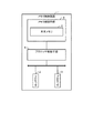
本発明の第1の実施形態を、図1を参照して説明する。図1は、メモリ制御装置1の構成を示す機能ブロック図である。なお、本実施形態では、メモリ制御装置1の概略を説明する。
<
A first embodiment of the present invention will be described with reference to FIG. FIG. 1 is a functional block diagram showing the configuration of the
図1に示すように、本実施形態におけるメモリ制御装置1は、データを格納するメモリ領域を利用して演算処理を行う複数のプロセッサ2,3と、当該複数のプロセッサ2,3にて共有される共有メモリ4と、上記プロセッサ2,3から発行された占有要求/占有解除要求を受け付けて、上記プロセッサ2,3毎の上記共有メモリ4に対する占有/占有解除を制御するメモリ制御手段5と、上記プロセッサ2,3から発行された上記共有メモリ4に対する占有要求/占有解除要求を上記メモリ制御手段5に通知するプロセッサ制御手段6と、を備えている。
As shown in FIG. 1, the
そして、上記メモリ制御手段5は、上記プロセッサ2,3による上記共有メモリ4の占有状態を上記プロセッサ制御手段6に通知する機能を有している。さらに、上記プロセッサ制御手段6は、上記メモリ制御手段5からの通知に基づいて上記共有メモリ4の占有状態を管理すると共に、当該共有メモリ4が所定の上記プロセッサ2に占有されている場合に、他の上記プロセッサ3から発行された上記共有メモリ4に対する占有要求の上記メモリ制御手段に対する通知を停止する機能を有している。
The memory control means 5 has a function of notifying the processor control means 6 of the occupation state of the shared memory 4 by the
また、上記メモリ制御装置1では、上記メモリ制御手段5は、上記共有メモリが上記所定のプロセッサに占有されているときに上記他のプロセッサから発行された占有要求が通知された場合に、当該他のプロセッサによる占有要求を却下して、上記プロセッサ制御手段に通知する、という機能を有している。そして、上記プロセッサ制御手段6は、上記メモリ制御手段からの通知に基づいて上記共有メモリが占有されている状態である場合に、占有要求が却下されている上記他のプロセッサから発行された占有要求の上記メモリ制御手段に対する通知を停止する、という機能を有している。
In the
また、上記メモリ制御装置1では、上記メモリ制御手段5は、上記プロセッサによる上記共有メモリの占有を解除したときに当該占有解除を上記プロセッサ制御手段に通知する機能を有している。そして、上記プロセッサ制御手段6は、上記メモリ制御手段からの通知に基づいて上記共有メモリの占有状態が解除されたときに、占有要求が却下されている上記他のプロセッサから発行された占有要求の上記メモリ制御手段に対する通知の停止を解除する、という機能を有している。
In the
また、上記メモリ制御装置1では、上記メモリ制御手段5は、上記各プロセッサから発行された占有要求の通知の有無を管理して、当該管理内容を表す占有要求管理情報を上記プロセッサ制御手段に通知する、という機能を有している。そして、上記プロセッサ制御手段6は、上記メモリ制御手段から通知された上記占有要求管理情報に基づいて、上記プロセッサ毎に当該プロセッサから発行された占有要求の上記メモリ制御手段に対する通知を行うか否か決定する、という機能を有している。
In the
より具体的に、上記メモリ制御装置1では、上記メモリ制御手段5は、占有要求が通知された上記プロセッサに対応するフラグをセットすると共に、上記共有メモリの占有解除を行った上記プロセッサに対応するフラグをリセットして、上記プロセッサ毎に設定された上記フラグを管理し、このフラグのセット合計数を上記占有要求管理情報として、上記プロセッサからの占有要求を却下したときに上記プロセッサ制御手段に通知する、という機能を有している。そして、上記プロセッサ制御手段6は、上記フラグのセット合計数を上記占有要求が却下されたプロセッサに対応して設定すると共に、上記メモリ制御手段から占有解除通知を受けたときに上記各プロセッサに対応して設定された上記フラグのセット合計数を減算し、当該フラグのセット合計数が少ない上記プロセッサから発行された占有要求を優先して上記メモリ制御手段に通知する、という機能を有している。
More specifically, in the
そして、上記メモリ制御装置1では、上記プロセッサ制御手段6は、上記メモリ制御手段から占有解除通知を受けたときに、上記フラグのセット合計数が「1」である上記プロセッサから発行された占有要求を優先して上記メモリ制御手段に通知する、という機能を有している。
In the
上記構成のメモリ制御装置1によると、まず、所定のプロセッサが共有メモリを占有することを要求する際には、占有要求をプロセッサ制御手段に発行する。そして、プロセッサ制御手段は、占有要求をメモリ制御手段に通知し、これを受けたメモリ制御手段は、先行する占有要求がないので、所定のプロセッサに共有メモリを占有させるよう制御する。その後、他のプロセッサから共有メモリの占有要求が発行されると、上記同様に、プロセッサ制御手段が占有要求をメモリ制御手段に通知する。このとき、メモリ制御手段は、先行する所定のプロセッサの占有要求があるので、他のプロセッサによる占有を行わず、占有失敗をプロセッサ制御手段及び他のプロセッサに通知する。つまり、メモリ制御手段は、共有メモリは占有されていることをプロセッサ制御手段に通知する。これに応じて、プロセッサ制御手段は、この通知に基づいて共有メモリが占有されていることを管理する。
According to the
その後、上述したように占有に失敗した他のプロセッサが、再度、共有メモリへの占有要求を発行すると、プロセッサ制御手段は、共有メモリが占有されているため、占有要求をメモリ制御手段に対して通知しない。一方で、所定のプロセッサから占有解除要求が発行されると、この占有解除要求をプロセッサ制御手段がメモリ制御手段に通知する。すると、メモリ制御手段は所定のプロセッサによる共有メモリの占有を解除し、プロセッサ制御手段に通知する。そして、プロセッサ制御手段は、共有メモリの占有が解除されているので、これまでメモリ制御手段に通知することを停止していた他のプロセッサから発行された占有要求の通知の停止を解除する。これにより、プロセッサ制御手段は、他のプロセッサからの占有要求をメモリ制御手段に通知し、これを受けたメモリ制御手段は、他のプロセッサが共有メモリを占有できるよう制御する。 Thereafter, when another processor that has failed to occupy again issues an occupancy request to the shared memory as described above, the processor control means sends the occupancy request to the memory control means because the shared memory is occupied. Do not notify. On the other hand, when an exclusive release request is issued from a predetermined processor, the processor control means notifies the memory control means of this exclusive release request. Then, the memory control unit releases the occupation of the shared memory by a predetermined processor and notifies the processor control unit. The processor control unit releases the suspension of the notification of the occupation request issued from another processor that has stopped the notification to the memory control unit until now because the occupation of the shared memory is released. Thereby, the processor control means notifies the memory control means of an occupancy request from another processor, and the memory control means that receives the request controls the other processor to occupy the shared memory.
以上のように、本発明によると、メモリ制御手段に占有要求が頻繁に通知されることを抑制することができ、先行して共有メモリを占有しているプロセッサから占有解除要求が発行された場合に、当該占有解除要求が他の要求と競合することを抑制することができる。その結果、迅速に共有メモリの占有解除を実行することができ、他のプロセッサによる共有メモリの占有遅延を抑制でき、システム性能の向上を図ることができる。 As described above, according to the present invention, when an exclusive request is issued from a processor that previously occupies the shared memory, it is possible to suppress frequent notification of the exclusive request to the memory control means. In addition, it is possible to prevent the exclusive release request from competing with other requests. As a result, the shared memory occupation release can be executed quickly, the shared memory occupation delay by other processors can be suppressed, and the system performance can be improved.
また、上述したメモリ制御装置のプロセッサ制御手段6は、メモリ制御用プログラムが組み込まれることで実現できる。 The processor control means 6 of the memory control device described above can be realized by incorporating a memory control program.
具体的に、本発明の他の形態であるメモリ制御用プログラムは、
データを格納するメモリ領域を利用して演算処理を行う複数のプロセッサと、
当該複数のプロセッサにて共有される共有メモリと、
上記プロセッサから発行された占有要求/占有解除要求を受け付けて、上記プロセッサ毎の上記共有メモリに対する占有/占有解除を制御するメモリ制御手段と、
上記プロセッサから発行された上記共有メモリに対する占有要求/占有解除要求を上記メモリ制御手段に通知するプロセッサ制御手段と、
を備えたメモリ制御装置の上記プロセッサ制御手段に、
上記メモリ制御手段から通知された上記プロセッサによる上記共有メモリの占有状態に基づいて当該共有メモリの占有状態を管理すると共に、当該共有メモリが所定の上記プロセッサに占有されている場合に、他の上記プロセッサから発行された上記共有メモリに対する占有要求の上記メモリ制御手段に対する通知を停止する処理、
を実現させるためのプログラムである。
Specifically, the memory control program according to another embodiment of the present invention is:
A plurality of processors that perform arithmetic processing using a memory area for storing data;
A shared memory shared by the plurality of processors;
Memory control means for accepting an occupancy request / occupancy release request issued from the processor and controlling occupancy / occupancy release for the shared memory for each processor;
Processor control means for notifying the memory control means of an occupancy request / occupancy release request for the shared memory issued by the processor;
In the processor control means of the memory control device comprising:
The occupancy state of the shared memory is managed based on the occupancy state of the shared memory by the processor notified from the memory control means, and when the shared memory is occupied by a predetermined processor, the other A process for stopping notification to the memory control means of the occupation request for the shared memory issued by the processor;
It is a program for realizing.
そして、上記プログラムは、
上記プロセッサ制御手段に、
上記メモリ制御手段が、上記共有メモリが上記所定のプロセッサに占有されているときに上記他のプロセッサから発行された占有要求が通知された場合に、当該他のプロセッサによる占有要求を却下して、占有失敗を通知してきた場合に、当該通知に基づいて、上記共有メモリが占有されている状態である場合に、上記占有要求が却下されている他のプロセッサから発行された占有要求の上記メモリ制御手段に対する通知を停止する処理、
を実現させるためのプログラムである。
And the above program
In the processor control means,
When the memory control means is notified of an occupancy request issued from the other processor when the shared memory is occupied by the predetermined processor, it rejects the occupancy request by the other processor, The memory control of the occupancy request issued from another processor in which the occupancy request is rejected when the occupancy failure is notified and the shared memory is in an occupied state based on the notification Processing to stop notification to the means,
It is a program for realizing.
また、上述したメモリ制御装置1の作動により実行されるメモリ制御方法は、
データを格納するメモリ領域を利用して演算処理を行う複数のプロセッサと、
当該複数のプロセッサにて共有される共有メモリと、
上記プロセッサから発行された占有要求/占有解除要求を受け付けて、上記プロセッサ毎の上記共有メモリに対する占有/占有解除を制御するメモリ制御手段と、
上記プロセッサから発行された上記共有メモリに対する占有要求/占有解除要求を上記メモリ制御手段に通知するプロセッサ制御手段と、を備えたメモリ制御装置にて、
上記メモリ制御手段が、上記プロセッサによる上記共有メモリの占有状態を上記プロセッサ制御手段に通知し、
上記プロセッサ制御手段が、上記メモリ制御手段からの通知に基づいて上記共有メモリの占有状態を管理すると共に、当該共有メモリが所定の上記プロセッサに占有されている場合に、他の上記プロセッサから発行された上記共有メモリに対する占有要求の上記メモリ制御手段に対する通知を停止する、
という構成を有する。
The memory control method executed by the operation of the
A plurality of processors that perform arithmetic processing using a memory area for storing data;
A shared memory shared by the plurality of processors;
Memory control means for accepting an occupancy request / occupancy release request issued from the processor and controlling occupancy / occupancy release for the shared memory for each processor;
A processor control means for notifying the memory control means of an exclusive request / occupancy release request for the shared memory issued by the processor;
The memory control means notifies the processor control means of the occupation state of the shared memory by the processor;
The processor control means manages the occupation state of the shared memory based on a notification from the memory control means, and is issued from another processor when the shared memory is occupied by a predetermined processor. Stop the notification to the memory control means of the occupation request to the shared memory,
It has the composition.
そして、上記メモリ制御方法では、
上記メモリ制御手段が、上記共有メモリが上記所定のプロセッサに占有されているときに上記他のプロセッサから発行された占有要求が通知された場合に、当該他のプロセッサによる占有要求を却下して、占有失敗を当該他のプロセッサを制御する上記プロセッサ制御手段に通知し、
上記プロセッサ制御手段が、上記メモリ制御手段からの通知に基づいて上記共有メモリが占有されている状態である場合に、上記占有要求が却下されている他のプロセッサから発行された占有要求の上記メモリ制御手段に対する通知を停止する、
という構成を有する。
In the memory control method,
When the memory control means is notified of an occupancy request issued from the other processor when the shared memory is occupied by the predetermined processor, it rejects the occupancy request by the other processor, Notifying the processor control means for controlling the other processor of the occupation failure,
When the processor control means is in a state where the shared memory is occupied based on a notification from the memory control means, the memory of the occupation request issued from another processor for which the occupation request is rejected Stop notification to control means,
It has the composition.
上述した構成を有する、プログラム、又は、メモリ制御方法、の発明であっても、上記メモリ制御装置と同様の作用を有するために、上述した本発明の目的を達成することができる。 Even the invention of the program or the memory control method having the above-described configuration can achieve the above-described object of the present invention because it has the same operation as the above-described memory control device.
<実施形態2>
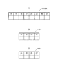
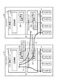
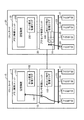
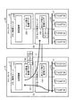
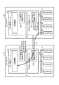
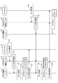
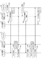
本発明の第2の実施形態を、図2乃至図10を参照して説明する。図2は、マルチプロセッサシステムの構成を示すブロック図である。図3は、マルチプロセッサシステム内で設定されるフラグのデータ構造を示す図である。図4乃至図7は、マルチプロセッサシステムの動作を示す説明図である。図8乃至図10は、マルチプロセッサシステムの動作を示すシーケンス図である。なお、本実施形態は、上述した実施形態1にて開示したメモリ制御装置の具体的な一例を示すものである。
<
A second embodiment of the present invention will be described with reference to FIGS. FIG. 2 is a block diagram showing the configuration of the multiprocessor system. FIG. 3 is a diagram showing a data structure of flags set in the multiprocessor system. 4 to 7 are explanatory diagrams showing the operation of the multiprocessor system. 8 to 10 are sequence diagrams showing the operation of the multiprocessor system. Note that the present embodiment shows a specific example of the memory control device disclosed in the first embodiment.
[構成]
図2に示すように、本実施形態におけるマルチプロセッサシステムは、CELLカード10,20を1つ備えている。そして、一方のCELLカード10は、データを格納するメモリ領域を利用して演算処理を行う複数のプロセッサ14,15,16,17と、当該複数のプロセッサ14〜17にて共有される共有メモリである記憶装置101と、を備えている。また、複数のプロセッサ14〜17にシステムバス13を介して接続されたプロセッサ制御ユニット12(プロセッサ制御手段)と、このプロセッサ制御ユニット12に接続されたメモリ制御ユニット11(メモリ制御手段)と、を備えている。そして、上記メモリ制御ユニット11は、ロック要求管理フラグ102と上記記憶装置101とを備えている。また、上記プロセッサ制御ユニット12は、再ロック発行管理フラグ103を備えている。
[Constitution]
As shown in FIG. 2, the multiprocessor system according to the present embodiment includes one
また、他方のCELLカード20も、上記一方のCELLカード10とほぼ同様の構成を採っている。つまり、CELLカード20は、データを格納するメモリ領域を利用して演算処理を行う複数のプロセッサ24,25,26,27と、当該複数のプロセッサ24〜27にて共有される共有メモリである記憶装置201と、を備えている。また、複数のプロセッサ24〜27にシステムバス23を介して接続されたプロセッサ制御ユニット22(プロセッサ制御手段)と、このプロセッサ制御ユニット22に接続されたメモリ制御ユニット21(メモリ制御手段)と、を備えている。そして、上記メモリ制御ユニット21は、ロック要求管理フラグ202と上記記憶装置201とを備えている。また、上記プロセッサ制御ユニット22は、再ロック発行管理フラグ203を備えている。
Also, the
また、上記2つのCELLカード10,20は、それぞれが装備しているプロセッサ制御ユニット12,22同士を専用インタフェースで接続することで、相互に接続している。以下、各構成についてさらに詳述する。なお、CELLカード10,20は、それぞれほぼ同一の構成を採っているため、以下では、CELLカード10の構成についてのみ説明し、CELLカード20の構成についてはその説明を省略する。
Further, the two
まず、上記プロセッサ14〜17は、それぞれいずれかの記憶装置101,201に対して、メモリアクセスリクエストを発行する。例えば、プロセッサ14は、記憶装置101のメモリ領域を使用して所定の処理を実行する際には、当該記憶装置101を占有することを要求するロック命令(占有要求)を発行する。また、プロセッサ14は、記憶装置101を使用して所定の処理が終了した後には、当該記憶装置101の占有を解除するアンロック命令(占有解除要求)を発行する。さらに、プロセッサ14は、後述するように記憶装置101に対するロック命令を発行したものの、メモリ制御ユニット11からロック失敗が通知された場合には、その後、一定の間隔にてロック命令を発行し続けることとなる。
First, the
なお、各プロセッサ14〜17,24〜27は、いずれも自身が装備されていない他のCELLカード10,20に装備されている記憶装置101,201に対しても、上述したロック命令及びアンロック命令を発行することができる。
Each of the
上記プロセッサ制御ユニット12は、プロセッサ14〜17からロック命令あるいはアンロック命令が発行されると、ロックあるいはアンロック対象となっている記憶装置101を装備したメモリ制御ユニット11に通知する。また、プロセッサ制御ユニット12は、他のCELLカード20に装備されたプロセッサ制御ユニット22と接続し、カード10,20間におけるデータの送受信を可能としている。例えば、プロセッサ14から発行されるロック/アンロック命令が他のカード20に装備された記憶装置201に対する命令である場合には、当該他のカード20に装備されたプロセッサ制御ユニット22を経由してメモリ制御ユニット21にロック/アンロック命令の送信を実行する。同様に、カード10に装備されたメモリ制御ユニット11からプロセッサ制御ユニット22やプロセッサ24に対して送信されるデータがある場合には、プロセッサ制御ユニット12は、かかるデータを、プロセッサ制御ユニット22に対して送信する。
When a lock command or an unlock command is issued from the
また、上記メモリ制御ユニット11は、上述したように、各プロセッサ14〜17,24〜27から発行されたロック/アンロック命令を受け付けて、当該各プロセッサ14〜17,24〜27に対する記憶装置101のロック(占有)/アンロック(占有解除)を制御する。このとき、システム全体で複数のプロセッサ14からロック命令やアンロック命令が競合した場合には、これら命令の調停を行う。そして、メモリ制御ユニット11は、ロック命令の競合を管理するために、ロック要求管理フラグ102を利用している。このロック要求管理フラグ102は、システム全体において競合対象となるプロセッサ14〜17,24〜27を判別できるフラグを保持するよう構成されている。
Further, as described above, the
具体的に、ロック要求管理フラグ102は、図3(A)に示すように、各プロセッサ単位で管理するよう構成されている。例えば、図3(A)に示す例では、上段にはプロセッサの符号を設定しており、下段には上段のプロセッサに対応するフラグを設定可能となっている。そして、メモリ制御ユニット11は、ロック命令が発行されるとそのプロセッサのフラグをセットし、アンロック命令が発行されるとリセットする。つまり、ロック要求管理フラグ102には、メモリ制御ユニット11にて、ロック要求してきたプロセッサのフラグがセットされる。
Specifically, as shown in FIG. 3A, the lock
そして、上記メモリ制御ユニット11は、ロック命令を受け付けたときに、ロック要求管理フラグ102内のどのプロセッサのフラグも「0」である場合には、先行するロック命令がなく、記憶装置101がいずれかのプロセッサにロックされていない、と判断できる。この場合には、メモリ制御ユニット11は、受け付けたロック命令に従って、かかる命令を要求してきたプロセッサに記憶装置101を占有させるようロック制御し、当該プロセッサのフラグを「1」にセットする。そして、その後、このプロセッサからアンロック命令を受け付けた場合には、メモリ制御ユニット11は、アンロック命令を実行し、当該プロセッサのフラグを「0」にリセットする。さらに、メモリ制御ユニット11がロック命令を受けた場合に、すでに他のプロセッサのフラグが「1」である場合には、記憶装置101がすでにセット(占有)されているため、ロック失敗を返却する。このとき、メモリ制御ユニット11は、ロックは失敗したが、このロック要求をしてきたプロセッサのフラグを「1」にセットする。
When the
また、メモリ制御ユニット11は、上述したロック/アンロック制御の結果、つまり、記憶装置101のロック/アンロック状態(占有状態)を、各プロセッサ制御ユニット12,22に通知する。例えば、ロック成功時には、ロック要求してきたプロセッサに接続されたプロセッサ制御ユニットを介して、当該プロセッサにロック成功の旨を通知する。また、メモリ制御ユニット11は、ロック失敗時には、ロック要求してきたプロセッサに接続されたプロセッサ制御ユニットを介して、当該プロセッサにロック失敗の旨を通知する。これに加えて、メモリ制御ユニット11は、ロック要求管理フラグ102内でセットされているフラグの合計数(セット合計数)をプロセッサ制御ユニット12,22に通知する。つまり、メモリ制御ユニット11は、上記ロック要求管理フラグ102を用いて、各プロセッサから発行された占有要求の通知の有無を管理して、当該管理内容を表すフラグ合計数つまりセット要求してきたプロセッサの台数、を占有要求管理情報として、プロセッサ制御ユニット12,22に通知する。
Further, the
一方で、メモリ制御ユニット11は、アンロック命令実行時には、アンロック要求してきたプロセッサに接続されたプロセッサ制御ユニットを介して、当該プロセッサにアンロック命令実行の旨を通知する。これに加えて、メモリ制御ユニット11は、上述したフラグの合計数を減算する指令をプロセッサ制御ユニット12,22に通知する。
On the other hand, when executing the unlock instruction, the
そして、上記プロセッサ制御ユニット12,22は、上述したように、再ロック発行管理フラグ103を備えている。このフラグ103は、プロセッサ14〜17が発行するロック命令が1度失敗した後、2回目のロック命令を発行するタイミングを管理するために用いられる。ここで、図3(B)に、再ロック発行管理フラグ103の構成の一例を示す。この図に示すように、再ロック発行管理フラグ103は、同一カード10内に装備されたプロセッサ毎にデータを設定可能なよう構成されている。そして、この各プロセッサ毎のフラグ103には、対応するプロセッサがロック要求を行ったがロックが失敗したときにメモリ制御ユニット11から通知される上記フラグ合計数が格納される。なお、図3(C)には、CELLカード20に装備された再ロック発行管理フラグ203の構成を示しているが、この図に示すように、当該カード20に装備されたプロセッサ24〜27毎に設定可能な構成となっている。
The
そして、上記プロセッサ制御ユニット12は、上述したように、プロセッサのロック失敗の通知と共にメモリ制御ユニット11からフラグの合計数を通知された場合には、このフラグの合計数を当該ロックが失敗したプロセッサに対応する再ロック発行管理フラグに設定する。また、メモリ制御ユニット11からアンロック命令実行の旨及びフラグ合計数の減算通知があった場合には、全てのプロセッサに対応する再ロック発行管理フラグをそれぞれ「1」減算する。
When the
さらに、プロセッサ制御ユニット12は、上記再ロック発行管理フラグ103内の各プロセッサに対応するフラグ合計数の値に応じて、一度ロック要求が失敗しているプロセッサから発行された再ロック要求を、メモリ制御ユニット11,12に通知するか否かを制御している。具体的に、プロセッサ制御ユニット12は、一度ロック要求に失敗しているプロセッサに設定されているフラグ合計数の値が「1」より大きい場合、つまり、「2」以上である場合には、当該フラグ合計数から記憶装置101が占有状態であることがわかるため、当該プロセッサから再ロック命令が発行されたとしても、メモリ制御ユニット11,21には通知しない。一方で、プロセッサ制御ユニット12は、一度ロック要求に失敗しているプロセッサに設定されているフラグ合計数の値が「1」である場合には、当該フラグ合計数から記憶装置101が占有状態ではないことがわかるため、当該プロセッサから発行された再ロック命令をメモリ制御ユニット11,21に通知する。
Further, the
なお、上述したメモリ制御ユニット11及びプロセッサ制御ユニット12が有する機能は、それぞれに所定のプログラムが組み込まれることによって実現される。また、上記では、主に一方のCELLカード10に装備された構成についてのみ説明したが、他方のCELLカード20も同様の構成を備えている。
Note that the functions of the
[動作]
次に、上述した構成のマルチプロセッサシステムの動作を、図4乃至図10を参照して説明する。以下では、CELLカード10の記憶装置101に対して、CELLカード10のプロセッサ14と、CELLカード20のプロセッサ24と、からロック命令が発行され、メモリロック対象が記憶装置101であり、ロック命令が競合する場合の動作を説明する。
[Operation]
Next, the operation of the multiprocessor system configured as described above will be described with reference to FIGS. In the following, a lock command is issued from the
まず、プロセッサ14からメモリロック命令が発行されると(図8のステップS1)、これを受けたプロセッサ制御ユニット12は、メモリ制御ユニット11にロック命令を発行する(図4の矢印Y1、図8のステップS2)。これを受け付けたメモリ制御ユニット11は、ロック要求管理フラグ102が全て「0」であるので、先行するメモリロック命令が無く、ロック成功とし、ロック成功時の処理を実施する(図8のステップS3)。このとき、ロック要求管理フラグ102のプロセッサ14のフラグを、「1」にセットする(図8のステップS4)。また、プロセッサ制御ユニット12及びプロセッサ14には、ロック成功が返却される(図8のステップS5)。
First, when a memory lock command is issued from the processor 14 (step S1 in FIG. 8), the
続いて、プロセッサ14からメモリロック命令が発行されると(図8のステップS6)、これを受けたプロセッサ制御ユニット22は、プロセッサ制御ユニット12を介してメモリ制御ユニット11にロック命令を発行する(図4の矢印Y2、図8のステップS7)。これを受け付けたメモリ制御ユニット11は、ロック要求管理フラグ102を調べると、すでにフラグが「1」にセットされたプロセッサ14が存在するため、先行のプロセッサ14から発行されたロック命令があり、記憶装置101はロック状態であることが分かる。従って、プロセッサ24からのロック命令は失敗とする(図8のステップS8)。このとき、プロセッサ24からロック命令があったため、ロック要求管理フラグ102のプロセッサ24に対応するフラグを、「1」にセットする(図8のステップS9)。さらに、メモリ制御ユニット11は、プロセッサ制御ユニット12を介してプロセッサ制御ユニット22及びプロセッサ24に、ロック失敗を返却すると共に、ロック要求管理フラグ102に設定されているフラグ合計数である値「2」を通知する(図4の矢印Y3、図8のステップS10)。
Subsequently, when a memory lock command is issued from the processor 14 (step S6 in FIG. 8), the
そして、これを受けたプロセッサ制御ユニット22は、上記フラグ合計数である値「2」を、再ロック発行管理フラグ203内にプロセッサ24に対応して設定する(図8のステップS11)。これにより、プロセッサ制御ユニット22は、2台のプロセッサからロック要求があったことがわかり、プロセッサ24がロック要求を行う前に先行してロック要求を行ったプロセッサが1台存在して、ロック状態にある、ということがわかる。
Upon receiving this, the
その後、プロセッサ14にて記憶装置101が占有状態にある場合であっても(図5の矢印Y4)、ロック失敗の通知を受けたプロセッサ24は、一定の間隔にて、記憶装置101に対する再ロック命令を発行する(図9のステップS21)。ところが、これを受けたプロセッサ制御ユニット22は、再ロック発行管理フラグ203のプロセッサ24用のフラグに値「2」がセットされているため、再ロック命令を阻止する(図5の矢印Y5、図9のステップS22)。つまり、プロセッサ制御ユニット22は、プロセッサ24から発行された再ロック命令を、CELLカード10のメモリ制御ユニット11に通知することを停止する。この再ロック命令の阻止は、後述するように、フラグの値が「1」となるまで続くこととなる。
Thereafter, even when the
その後、記憶装置101とロック状態にあったプロセッサ14が、ロック成功時の処理が完了すると、アンロック命令を発行する(図9のステップS31)。これを受けたプロセッサ制御ユニット12は、メモリ制御ユニット11にアンロック命令を発行する(図6の矢印Y6、図9のステップS32)。このとき、上述したようにプロセッサ24からの再ロック命令がメモリ制御ユニット11に対して発行されていないので、アンロック命令は他の命令と競合せず、メモリ制御ユニット11は、他の命令の処理を待つことなくアンロック命令を実行することができる(図9のステップS33)。
Thereafter, the
そして、メモリ制御ユニット11は、アンロック命令を実行すると、プロセッサ14による記憶装置101の占有状態を解除し、ロック要求管理フラグ102のプロセッサ14用のフラグを「0」にリセットする(図9のステップS34)。また、メモリ制御ユニット11は、プロセッサ制御ユニット12及びプロセッサ14、さらには、プロセッサ制御ユニット22にアンロック通知を行う(図6の矢印Y7、図9のステップS35)。
When executing the unlock instruction, the
続いて、プロセッサ制御ユニット22は、メモリ制御ユニット11からアンロック通知を受けたため、再ロック発行管理フラグ203に設定されている全てのプロセッサ用のフラグ合計数を、それぞれ「1」だけ減算する(図9のステップS36)。すると、再ロック発行管理フラグ203のプロセッサ24用のフラグの値は「1」となる。これにより、プロセッサ24のみがロック要求を行っていることとなり、記憶装置101は他のプロセッサに占有されていない、ということがわかる。従って、プロセッサ制御ユニット22は、プロセッサ24からの再ロック命令の発行抑止を解除する。
Subsequently, since the
その後、プロセッサ24からロック命令が発行されると(図10のステップS41)、プロセッサ制御ユニット22は、プロセッサ制御ユニット12を経由してメモリ制御ユニット11にロック命令を発行する(図7の矢印Y8、図10のステップS42)。すると、すでに先行するメモリロック命令が完了した(無い)状態なので、記憶装置101に対するプロセッサ24のロックが成功し、ロック成功時の処理を実施することになる(図10のステップS43)。このとき、既にロック要求管理フラグ102のプロセッサ24のフラグは「1」のままである。また、プロセッサ制御ユニット12及びプロセッサ14に、ロック成功を返却する(図10のステップS44)。
Thereafter, when a lock command is issued from the processor 24 (step S41 in FIG. 10), the
その後、記憶装置101とロック状態にあったプロセッサ24が、ロック成功時の処理が完了すると、アンロック命令を発行する(図10のステップS45)。これを受けたプロセッサ制御ユニット22は、プロセッサ制御ユニット12を介してメモリ制御ユニット11にアンロック命令を発行する(図10のステップS46)。
Thereafter, the
そして、メモリ制御ユニット11は、アンロック命令を実行して(図10のステップS47)、プロセッサ24による記憶装置101の占有状態を解除し、ロック要求管理フラグ102のプロセッサ24用のフラグを「0」にリセットする(図10のステップS48)。また、メモリ制御ユニット11は、プロセッサ制御ユニット12,22及びプロセッサ24にアンロック通知を行う(図10のステップS49)。
Then, the
続いて、プロセッサ制御ユニット22は、メモリ制御ユニット11からアンロック通知を受けたため、再ロック発行管理フラグ203に設定されている全てのプロセッサ用のフラグ合計数を、それぞれ「1」だけ減算する(図10のステップS50)。
Subsequently, since the
以上のように、本発明によると、メモリ制御ユニットに一度ロックを失敗しているプロセッサからの再ロック命令が、頻繁に通知されることを抑制することができる。従って、先行して記憶装置をロックしているプロセッサからアンロック命令が発行された場合であっても、当該アンロック命令が他の要求と競合することを抑制することができる。その結果、迅速に記憶装置のアンロックを実行することができ、他のプロセッサによる記憶装置のロック遅延を抑制でき、システム性能の向上を図ることができる。 As described above, according to the present invention, it is possible to prevent the memory control unit from being frequently notified of a relock instruction from a processor that has failed to be locked once. Therefore, even when an unlock instruction is issued from a processor that has previously locked the storage device, it is possible to prevent the unlock instruction from competing with other requests. As a result, the storage device can be unlocked quickly, the storage device lock delay caused by another processor can be suppressed, and the system performance can be improved.
なお、上記では、2つのプロセッサからロック命令が競合した場合を説明したが、3台以上のプロセッサからロック命令が発行された場合も同様である。このとき、ロック要求を行ったプロセッサの台数が増えるため、再ロック発行管理フラグ103,203に記憶される各プロセッサ毎の値は、ロック要求が遅くプロセッサほど大きな値となる。 In the above description, the case where the lock instructions compete with each other from the two processors has been described, but the same applies when the lock instructions are issued from three or more processors. At this time, since the number of processors that have issued a lock request increases, the value for each processor stored in the re-lock issue management flags 103 and 203 becomes a larger value as the processor has a slower lock request.
例えば、プロセッサ14,24,25の順にロック命令を発行した場合を考える。まず、プロセッサ14がロックに成功すると、その後にロック命令を発行したプロセッサ24,25はロックに失敗する。そして、プロセッサ24がロックに失敗した段階では、プロセッサ14,24といった2台のプロセッサがロック要求した状態であるため、プロセッサ24用の再ロック発行管理フラグ203の値は、上述したように「2」となる。一方、プロセッサ25がロックに失敗した段階では、プロセッサ14,24,25といった3台のプロセッサがロック要求した状態であるため、プロセッサ25用の再ロック発行管理フラグ203の値は、「3」となる。このような状態では、プロセッサ24,25からのロック命令は、メモリ制御ユニット11には発行されない。
For example, consider a case where lock instructions are issued in the order of the
その後、プロセッサ14がアンロックを行うと、各プロセッサ24,25用の再ロック発行管理フラグ203の値が「1」ずつ減算される。つまり、プロセッサ24のフラグが「1」となり、プロセッサ25のフラグが「2」となる。すると、次にプロセッサ24からの再ロック要求が発行されると、このロック要求はメモリ制御ユニット11に発行される。一方、プロセッサ25からの再ロック命令は、メモリ制御ユニット11には発行されない。その後、プロセッサ24がアンロックを行うと、プロセッサ25の再ロック発行管理フラグ203が「1」となるため、その後、プロセッサ25がロックを行うことができる。
Thereafter, when the
以上のように、上述した再ロック発行管理フラグの値を利用することで、プロセッサのロックの優先順位も管理することができる。 As described above, by using the value of the above-described relock issue management flag, it is possible to manage the priority of the lock of the processor.
本発明は、複数のプロセッサで記憶装置を共有するマルチプロセッサシステムに利用することができ、産業上の利用可能性を有する。 The present invention can be used for a multiprocessor system in which a plurality of processors share a storage device, and has industrial applicability.
1 メモリ制御装置
2,3 プロセッサ
4 共有メモリ
5 メモリ制御手段
6 プロセッサ制御手段
10,20 CELLカード
11,21 メモリ制御ユニット
12,22 プロセッサ制御ユニット
14,15,16,17,24,25,26,27 プロセッサ
101,201 記憶装置
102,202 ロック要求管理フラグ
103,203 再ロック発行管理フラグ
DESCRIPTION OF
Claims (10)
当該複数のプロセッサにて共有される共有メモリと、
前記プロセッサから発行された占有要求/占有解除要求を受け付けて、前記プロセッサ毎の前記共有メモリに対する占有/占有解除を制御するメモリ制御手段と、
前記プロセッサから発行された前記共有メモリに対する占有要求/占有解除要求を前記メモリ制御手段に通知するプロセッサ制御手段と、を備え、
前記メモリ制御手段は、前記プロセッサによる前記共有メモリの占有状態を前記プロセッサ制御手段に通知し、
前記プロセッサ制御手段は、前記メモリ制御手段からの通知に基づいて前記共有メモリの占有状態を管理すると共に、当該共有メモリが所定の前記プロセッサに占有されている場合に、他の前記プロセッサから発行された前記共有メモリに対する占有要求の前記メモリ制御手段に対する通知を停止する、
メモリ制御装置。 A plurality of processors that perform arithmetic processing using a memory area for storing data;
A shared memory shared by the plurality of processors;
Memory control means for accepting an occupancy request / occupancy release request issued from the processor and controlling occupancy / occupancy release for the shared memory for each processor;
Processor control means for notifying the memory control means of an exclusive request / exclusive request for the shared memory issued by the processor,
The memory control means notifies the processor control means of the occupation state of the shared memory by the processor;
The processor control unit manages an occupation state of the shared memory based on a notification from the memory control unit, and is issued from another processor when the shared memory is occupied by a predetermined processor. Stop the notification to the memory control means of the occupation request to the shared memory,
Memory controller.
前記メモリ制御手段は、前記共有メモリが前記所定のプロセッサに占有されているときに前記他のプロセッサから発行された占有要求が通知された場合に、当該他のプロセッサによる占有要求を却下して、前記プロセッサ制御手段に通知し、
前記プロセッサ制御手段は、前記メモリ制御手段からの通知に基づいて前記共有メモリが占有されている状態である場合に、占有要求が却下されている前記他のプロセッサから発行された占有要求の前記メモリ制御手段に対する通知を停止する、
メモリ制御装置。 The memory control device according to claim 1,
The memory control means rejects the occupation request by the other processor when the occupation request issued from the other processor is notified when the shared memory is occupied by the predetermined processor, Notifying the processor control means;
The processor control means, when the shared memory is occupied based on a notification from the memory control means, the memory of the occupation request issued from the other processor for which the occupation request is rejected Stop notification to control means,
Memory controller.
前記メモリ制御手段は、前記プロセッサによる前記共有メモリの占有を解除したときに当該占有解除を前記プロセッサ制御手段に通知し、
前記プロセッサ制御手段は、前記メモリ制御手段からの通知に基づいて前記共有メモリの占有状態が解除されたときに、占有要求が却下されている前記他のプロセッサから発行された占有要求の前記メモリ制御手段に対する通知の停止を解除する、
メモリ制御装置。 The memory control device according to claim 2,
The memory control means notifies the processor control means of the occupation release when releasing the occupation of the shared memory by the processor,
The processor control means is configured to control the memory of an occupancy request issued from the other processor whose occupancy request has been rejected when the occupancy state of the shared memory is released based on a notification from the memory control means. Cancel the suspension of notification to the means,
Memory controller.
前記メモリ制御手段は、前記各プロセッサから発行された占有要求の通知の有無を管理して、当該管理内容を表す占有要求管理情報を前記プロセッサ制御手段に通知し、
前記プロセッサ制御手段は、前記メモリ制御手段から通知された前記占有要求管理情報に基づいて、前記プロセッサ毎に当該プロセッサから発行された占有要求の前記メモリ制御手段に対する通知を行うか否か決定する、
メモリ制御装置。 The memory control device according to claim 3,
The memory control means manages the presence / absence of a notification of an exclusive request issued from each processor, and notifies the processor control means of exclusive request management information representing the management content,
The processor control means determines, based on the occupancy request management information notified from the memory control means, whether to notify the memory control means of an occupancy request issued from the processor for each processor;
Memory controller.
前記メモリ制御手段は、占有要求が通知された前記プロセッサに対応するフラグをセットすると共に、前記共有メモリの占有解除を行った前記プロセッサに対応するフラグをリセットして、前記プロセッサ毎に設定された前記フラグを管理し、このフラグのセット合計数を前記占有要求管理情報として、前記プロセッサからの占有要求を却下したときに前記プロセッサ制御手段に通知し、
前記プロセッサ制御手段は、前記フラグのセット合計数を前記占有要求が却下されたプロセッサに対応して設定すると共に、前記メモリ制御手段から占有解除通知を受けたときに前記各プロセッサに対応して設定された前記フラグのセット合計数を減算し、当該フラグのセット合計数が少ない前記プロセッサから発行された占有要求を優先して前記メモリ制御手段に通知する、
メモリ制御装置。 The memory control device according to claim 4,
The memory control unit sets a flag corresponding to the processor to which the occupation request is notified, and resets a flag corresponding to the processor that has released the occupation of the shared memory, and is set for each processor. The flag is managed, and the total number of sets of the flag is used as the occupancy request management information to notify the processor control means when the occupancy request from the processor is rejected,
The processor control means sets the total number of sets of the flags corresponding to the processor for which the occupancy request has been rejected, and sets corresponding to each processor when receiving the occupancy release notification from the memory control means Subtracting the set total number of the flag set, and giving priority to an exclusive request issued from the processor with a small total set number of the flag, and notifying the memory control means,
Memory controller.
前記プロセッサ制御手段は、前記メモリ制御手段から占有解除通知を受けたときに、前記フラグのセット合計数が「1」である前記プロセッサから発行された占有要求を優先して前記メモリ制御手段に通知する、
メモリ制御装置。 The memory control device according to claim 5,
When the processor control means receives the exclusive release notification from the memory control means, the processor control means gives priority to the exclusive request issued from the processor whose total number of sets of the flag is “1”, and notifies the memory control means To
Memory controller.
当該複数のプロセッサにて共有される共有メモリと、
前記プロセッサから発行された占有要求/占有解除要求を受け付けて、前記プロセッサ毎の前記共有メモリに対する占有/占有解除を制御するメモリ制御手段と、
前記プロセッサから発行された前記共有メモリに対する占有要求/占有解除要求を前記メモリ制御手段に通知するプロセッサ制御手段と、
を備えたメモリ制御装置の前記プロセッサ制御手段に、
前記メモリ制御手段から通知された前記プロセッサによる前記共有メモリの占有状態に基づいて当該共有メモリの占有状態を管理すると共に、当該共有メモリが所定の前記プロセッサに占有されている場合に、他の前記プロセッサから発行された前記共有メモリに対する占有要求の前記メモリ制御手段に対する通知を停止する処理、
を実現させるためのプログラム。 A plurality of processors that perform arithmetic processing using a memory area for storing data;
A shared memory shared by the plurality of processors;
Memory control means for accepting an occupancy request / occupancy release request issued from the processor and controlling occupancy / occupancy release for the shared memory for each processor;
Processor control means for notifying the memory control means of an exclusive request / exclusive request for the shared memory issued from the processor;
In the processor control means of the memory control device comprising:
When managing the occupation state of the shared memory based on the occupation state of the shared memory by the processor notified from the memory control means, and when the shared memory is occupied by the predetermined processor, the other A process for stopping notification to the memory control means of an occupation request for the shared memory issued by a processor;
A program to realize
前記プロセッサ制御手段に、
前記メモリ制御手段が、前記共有メモリが前記所定のプロセッサに占有されているときに前記他のプロセッサから発行された占有要求が通知された場合に、当該他のプロセッサによる占有要求を却下して、占有失敗を通知してきた場合に、当該通知に基づいて、前記共有メモリが占有されている状態である場合に、前記占有要求が却下されている他のプロセッサから発行された占有要求の前記メモリ制御手段に対する通知を停止する処理、
を実現させるためのプログラム。 A program according to claim 7, wherein
In the processor control means,
When the memory control means is notified of an occupation request issued from the other processor when the shared memory is occupied by the predetermined processor, the memory control means rejects the occupation request by the other processor, The memory control of the occupancy request issued from another processor to which the occupancy request has been rejected when the occupancy failure has been notified and the shared memory is in an occupied state based on the notification Processing to stop notification to the means,
A program to realize
当該複数のプロセッサにて共有される共有メモリと、
前記プロセッサから発行された占有要求/占有解除要求を受け付けて、前記プロセッサ毎の前記共有メモリに対する占有/占有解除を制御するメモリ制御手段と、
前記プロセッサから発行された前記共有メモリに対する占有要求/占有解除要求を前記メモリ制御手段に通知するプロセッサ制御手段と、を備えたメモリ制御装置にて、
前記メモリ制御手段が、前記プロセッサによる前記共有メモリの占有状態を前記プロセッサ制御手段に通知し、
前記プロセッサ制御手段が、前記メモリ制御手段からの通知に基づいて前記共有メモリの占有状態を管理すると共に、当該共有メモリが所定の前記プロセッサに占有されている場合に、他の前記プロセッサから発行された前記共有メモリに対する占有要求の前記メモリ制御手段に対する通知を停止する、
メモリ制御方法。 A plurality of processors that perform arithmetic processing using a memory area for storing data;
A shared memory shared by the plurality of processors;
Memory control means for accepting an occupancy request / occupancy release request issued from the processor and controlling occupancy / occupancy release for the shared memory for each processor;
A processor control means for notifying the memory control means of an occupancy request / occupancy release request for the shared memory issued by the processor;
The memory control means notifies the processor control means of the occupation state of the shared memory by the processor;
The processor control means manages the occupation state of the shared memory based on a notification from the memory control means, and is issued from another processor when the shared memory is occupied by a predetermined processor. Stop the notification to the memory control means of the occupation request to the shared memory,
Memory control method.
前記メモリ制御手段が、前記共有メモリが前記所定のプロセッサに占有されているときに前記他のプロセッサから発行された占有要求が通知された場合に、当該他のプロセッサによる占有要求を却下して、占有失敗を当該他のプロセッサを制御する前記プロセッサ制御手段に通知し、
前記プロセッサ制御手段が、前記メモリ制御手段からの通知に基づいて前記共有メモリが占有されている状態である場合に、前記占有要求が却下されている他のプロセッサから発行された占有要求の前記メモリ制御手段に対する通知を停止する、
メモリ制御方法。
The memory control method according to claim 9, comprising:
When the memory control means is notified of an occupation request issued from the other processor when the shared memory is occupied by the predetermined processor, the memory control means rejects the occupation request by the other processor, Notifying the processor control means for controlling the other processor of the occupation failure,
When the processor control means is in a state where the shared memory is occupied based on a notification from the memory control means, the memory of the occupancy request issued from another processor for which the occupancy request is rejected Stop notification to control means,
Memory control method.
Priority Applications (1)
| Application Number | Priority Date | Filing Date | Title |
|---|---|---|---|
| JP2008324989A JP5408701B2 (en) | 2008-12-22 | 2008-12-22 | Memory control device |
Applications Claiming Priority (1)
| Application Number | Priority Date | Filing Date | Title |
|---|---|---|---|
| JP2008324989A JP5408701B2 (en) | 2008-12-22 | 2008-12-22 | Memory control device |
Publications (2)
| Publication Number | Publication Date |
|---|---|
| JP2010146431A true JP2010146431A (en) | 2010-07-01 |
| JP5408701B2 JP5408701B2 (en) | 2014-02-05 |
Family
ID=42566783
Family Applications (1)
| Application Number | Title | Priority Date | Filing Date |
|---|---|---|---|
| JP2008324989A Expired - Fee Related JP5408701B2 (en) | 2008-12-22 | 2008-12-22 | Memory control device |
Country Status (1)
| Country | Link |
|---|---|
| JP (1) | JP5408701B2 (en) |
Cited By (1)
| Publication number | Priority date | Publication date | Assignee | Title |
|---|---|---|---|---|
| CN119440803A (en) * | 2024-09-29 | 2025-02-14 | 山东云海国创云计算装备产业创新中心有限公司 | A method, device, computer equipment and storage medium for obtaining control authority |
Citations (2)
| Publication number | Priority date | Publication date | Assignee | Title |
|---|---|---|---|---|
| JPH01280858A (en) * | 1988-05-06 | 1989-11-13 | Fujitsu Ltd | Lock control system for main storage device |
| JPH08320828A (en) * | 1995-05-24 | 1996-12-03 | Nec Eng Ltd | Multiprocessor system |
-
2008
- 2008-12-22 JP JP2008324989A patent/JP5408701B2/en not_active Expired - Fee Related
Patent Citations (2)
| Publication number | Priority date | Publication date | Assignee | Title |
|---|---|---|---|---|
| JPH01280858A (en) * | 1988-05-06 | 1989-11-13 | Fujitsu Ltd | Lock control system for main storage device |
| JPH08320828A (en) * | 1995-05-24 | 1996-12-03 | Nec Eng Ltd | Multiprocessor system |
Cited By (1)
| Publication number | Priority date | Publication date | Assignee | Title |
|---|---|---|---|---|
| CN119440803A (en) * | 2024-09-29 | 2025-02-14 | 山东云海国创云计算装备产业创新中心有限公司 | A method, device, computer equipment and storage medium for obtaining control authority |
Also Published As
| Publication number | Publication date |
|---|---|
| JP5408701B2 (en) | 2014-02-05 |
Similar Documents
| Publication | Publication Date | Title |
|---|---|---|
| CN101566977B (en) | Method, device and system of processor accessing shared data | |
| CN101802798A (en) | Avoiding livelock using intervention messages in a multi-core processor | |
| CN103699437B (en) | A kind of resource regulating method and equipment | |
| US9690737B2 (en) | Systems and methods for controlling access to a shared data structure with reader-writer locks using multiple sub-locks | |
| EP3114564B1 (en) | Transactional memory support | |
| CN104461707B (en) | a kind of lock request processing method and device | |
| US20110126208A1 (en) | Processing Architecture Having Passive Threads and Active Semaphores | |
| US6792497B1 (en) | System and method for hardware assisted spinlock | |
| US20170017435A1 (en) | Distributing computing system implementing a non-speculative hardware transactional memory and a method for using same for distributed computing | |
| CN102906703A (en) | Automatic suspend and resume in hardware transactional memory | |
| CN107168680B (en) | Atomic instructions with local scope limited to intermediate cache levels | |
| JP6129976B2 (en) | Method and apparatus using high efficiency atomic operations | |
| KR20120058553A (en) | Method and system for using temporary exclusive blocks for parallel accesses to operating means | |
| KR101084228B1 (en) | Information processing unit, cache memory control unit, and memory access order guarantee method | |
| JP5408701B2 (en) | Memory control device | |
| CN101908004A (en) | Promote the apparatus and method that request is carried out | |
| CN118885284B (en) | Distributed queue lock execution method based on key-value database | |
| JP2804478B2 (en) | Task control system and online transaction system | |
| CN101739341B (en) | System having processor and i/o controller | |
| JP6512087B2 (en) | Vehicle control device | |
| JPH09223032A (en) | Resource lock control mechanism | |
| KR102476933B1 (en) | An interconnect and method of operation of an interconnect | |
| JP2010026575A (en) | Scheduling method, scheduling device, and multiprocessor system | |
| US11500640B2 (en) | Circuitry to indicate an execution mode to access a secondary device | |
| CN120950278A (en) | An access method, apparatus, device, and computer-readable storage medium |
Legal Events
| Date | Code | Title | Description |
|---|---|---|---|
| RD03 | Notification of appointment of power of attorney |
Free format text: JAPANESE INTERMEDIATE CODE: A7423 Effective date: 20100702 |
|
| A621 | Written request for application examination |
Free format text: JAPANESE INTERMEDIATE CODE: A621 Effective date: 20111107 |
|
| RD07 | Notification of extinguishment of power of attorney |
Free format text: JAPANESE INTERMEDIATE CODE: A7427 Effective date: 20120712 |
|
| A977 | Report on retrieval |
Free format text: JAPANESE INTERMEDIATE CODE: A971007 Effective date: 20130510 |
|
| A131 | Notification of reasons for refusal |
Free format text: JAPANESE INTERMEDIATE CODE: A131 Effective date: 20130618 |
|
| A521 | Written amendment |
Free format text: JAPANESE INTERMEDIATE CODE: A523 Effective date: 20130730 |
|
| A01 | Written decision to grant a patent or to grant a registration (utility model) |
Free format text: JAPANESE INTERMEDIATE CODE: A01 Effective date: 20131008 |
|
| A61 | First payment of annual fees (during grant procedure) |
Free format text: JAPANESE INTERMEDIATE CODE: A61 Effective date: 20131031 |
|
| LAPS | Cancellation because of no payment of annual fees |