JP2010146887A - Electrode for nonaqueous secondary battery and method of manufacturing the same, and nonaqueous secondary battery - Google Patents
Electrode for nonaqueous secondary battery and method of manufacturing the same, and nonaqueous secondary battery Download PDFInfo
- Publication number
- JP2010146887A JP2010146887A JP2008323835A JP2008323835A JP2010146887A JP 2010146887 A JP2010146887 A JP 2010146887A JP 2008323835 A JP2008323835 A JP 2008323835A JP 2008323835 A JP2008323835 A JP 2008323835A JP 2010146887 A JP2010146887 A JP 2010146887A
- Authority
- JP
- Japan
- Prior art keywords
- active material
- binder
- positive electrode
- material layer
- secondary battery
- Prior art date
- Legal status (The legal status is an assumption and is not a legal conclusion. Google has not performed a legal analysis and makes no representation as to the accuracy of the status listed.)
- Pending
Links
Images
Classifications
-
- Y—GENERAL TAGGING OF NEW TECHNOLOGICAL DEVELOPMENTS; GENERAL TAGGING OF CROSS-SECTIONAL TECHNOLOGIES SPANNING OVER SEVERAL SECTIONS OF THE IPC; TECHNICAL SUBJECTS COVERED BY FORMER USPC CROSS-REFERENCE ART COLLECTIONS [XRACs] AND DIGESTS
- Y02—TECHNOLOGIES OR APPLICATIONS FOR MITIGATION OR ADAPTATION AGAINST CLIMATE CHANGE
- Y02E—REDUCTION OF GREENHOUSE GAS [GHG] EMISSIONS, RELATED TO ENERGY GENERATION, TRANSMISSION OR DISTRIBUTION
- Y02E60/00—Enabling technologies; Technologies with a potential or indirect contribution to GHG emissions mitigation
- Y02E60/10—Energy storage using batteries
Landscapes
- Secondary Cells (AREA)
- Battery Electrode And Active Subsutance (AREA)
Abstract
【課題】高い安全性と優れた電池特性とを兼ね備えた非水系二次電池を得る。
【解決手段】
正極10、負極11およびセパレータ12からなる捲回型電極群2、電池ケース19、非水電解液などを含む非水系二次電池において、次の電極を正極10および負極11のいずれか一方または両方に使用する。この電極は、集電体、活物質層および多孔質絶縁層を含み、活物質層は活物質とアニール処理により少なくとも一部が結晶化されたバインダとを含有し、アニール処理は145℃以上で実施され、多孔質絶縁層はバインダのアニール処理後に活物質層表面に形成されている。
【選択図】図1
A non-aqueous secondary battery having both high safety and excellent battery characteristics is obtained.
[Solution]
In a non-aqueous secondary battery including a wound electrode group 2 including a positive electrode 10, a negative electrode 11, and a separator 12, a battery case 19, a non-aqueous electrolyte, etc., the next electrode is either one or both of the positive electrode 10 and the negative electrode 11. Used for. The electrode includes a current collector, an active material layer, and a porous insulating layer. The active material layer contains an active material and a binder that is at least partially crystallized by annealing, and the annealing is performed at 145 ° C. or higher. The porous insulating layer is formed on the surface of the active material layer after the annealing treatment of the binder.
[Selection] Figure 1
Description
本発明は、非水系二次電池用電極とその製造方法および非水系二次電池に関する。さらに詳しくは、本発明は主に、非水系二次電池用電極の改良に関する。 The present invention relates to an electrode for a non-aqueous secondary battery, a manufacturing method thereof, and a non-aqueous secondary battery. More specifically, the present invention mainly relates to an improvement in an electrode for a non-aqueous secondary battery.
最近では、電子機器のポータブル化、コードレス化が急速に進み、これらの駆動用電源として、小型かつ軽量で、高エネルギー密度を有する二次電池が要望されている。特に、携帯電話は世界的に普及率が高く、カメラ機能、1セグメント放送受信機能、ミュージックプレーヤー機能などの多様な機能が付加されるようになっている。このため、電源として用いられる二次電池には一層の高容量化が要求されている。現在、電子機器用の二次電池としては、非水系二次電池が主流になっており、その中でもリチウムイオン二次電池が注目を集めている。リチウムイオン二次電池は高エネルギー密度を有し、高電圧放電が可能である。 Recently, electronic devices have become increasingly portable and cordless, and a secondary battery that is small and lightweight and has a high energy density is demanded as a power source for driving these devices. In particular, mobile phones have a high worldwide penetration rate, and various functions such as a camera function, a one-segment broadcast receiving function, and a music player function have been added. For this reason, the secondary battery used as a power source is required to have a higher capacity. At present, non-aqueous secondary batteries are mainly used as secondary batteries for electronic devices, and among them, lithium ion secondary batteries are attracting attention. The lithium ion secondary battery has a high energy density and can discharge at a high voltage.
リチウムイオン二次電池は、正極、負極およびセパレータからなる電極群と、非水電解質とを含む。セパレータは、正極と負極とを電気的に絶縁する機能を有し、主に樹脂製多孔質膜が使用されている。その材料としては、主に、ポリエチレン、ポリプロピレンなどのポリオレフィンが使用されている。しかしながら、樹脂製多孔質膜は高温下で収縮し易いため、樹脂製多孔質膜を含む電池では、安全性の面で改良の余地が残されている。 The lithium ion secondary battery includes an electrode group including a positive electrode, a negative electrode, and a separator, and a nonaqueous electrolyte. The separator has a function of electrically insulating the positive electrode and the negative electrode, and a resin porous film is mainly used. As the material, polyolefins such as polyethylene and polypropylene are mainly used. However, since the resin porous membrane easily contracts at high temperatures, there is still room for improvement in terms of safety in the battery including the resin porous membrane.
電池の安全性は、たとえば、釘刺し試験により評価される。釘刺し試験とは、電池の表面から内部の電極群に釘を突き刺して内部短絡を強制的に発生させ、発熱の程度を調べて電池の安全性を評価する方法である。樹脂製多孔質膜を含む電池に釘を刺すと、正極と負極とが導通し、釘を介して集電体間に短絡電流が流れ、ジュール熱が発生する。このジュール熱が樹脂製多孔質膜を収縮させ、短絡部分が拡大する。その結果、さらに発熱が激しくなり、電池温度が異常に高くなる現象が発生する可能性がある。この現象を異常発熱と呼ぶ。 The safety of the battery is evaluated by, for example, a nail penetration test. The nail penetration test is a method for evaluating battery safety by forcing a nail into an internal electrode group from the surface of a battery to forcibly generate an internal short circuit and examining the degree of heat generation. When a nail is pierced into a battery including a resin porous membrane, the positive electrode and the negative electrode are conducted, a short-circuit current flows between the current collectors via the nail, and Joule heat is generated. This Joule heat causes the resin porous membrane to shrink, and the short-circuit portion expands. As a result, there is a possibility that the heat generation becomes further intense and the battery temperature becomes abnormally high. This phenomenon is called abnormal heat generation.
樹脂製多孔質膜を含むリチウムイオン二次電池の安全性を向上させるため、種々の提案がなされている。たとえば、正極とセパレータとの間に、多孔質絶縁層を設けることが提案されている(たとえば、特許文献1参照)。多孔質絶縁層は、たとえば、無機充填材とバインダとを含有する。無機充填材としては、たとえば、アルミナ、シリカ、マグネシア、チタニア、ジルコニアなどの無機酸化物が挙げられている。また、バインダとしては、たとえば、ポリフッ化ビニリデン、ポリテトラフルオロエチレン、ポリアクリル酸系ゴム粒子などが挙げられている。 Various proposals have been made to improve the safety of lithium ion secondary batteries including a resin porous membrane. For example, it has been proposed to provide a porous insulating layer between the positive electrode and the separator (see, for example, Patent Document 1). The porous insulating layer contains, for example, an inorganic filler and a binder. Examples of the inorganic filler include inorganic oxides such as alumina, silica, magnesia, titania and zirconia. Examples of the binder include polyvinylidene fluoride, polytetrafluoroethylene, and polyacrylic acid rubber particles.
特許文献1の技術は、内部短絡の拡大を抑制できるため、リチウムイオン二次電池の安全性を高める上で非常に有効である。しかしながら、特許文献1の多孔質絶縁層の形成方法には、解決すべき課題がある。すなわち、特許文献1では、絶縁性粒子とバインダとを溶媒中に分散した絶縁層ペーストを活物質層に塗布乾燥することにより、活物質層表面に多孔質絶縁層を形成している。この場合、活物質層中のバインダが絶縁層ペーストの溶媒に対して高い溶解性を示すと、絶縁層ペーストの塗布後から乾燥までの間に、活物質層表面でバインダの膨潤や再溶解が起こり易くなる。
The technique of
たとえば、最近では活物質層のバインダには主にポリフッ化ビニリデン(以下「PVDF」とする)が使用され、絶縁層ペーストの溶媒にはN−メチル−2−ピロリドン(以下「NMP」とする)が使用されている。PVDFはNMPに溶解する。PVDFを含有する活物質層の表面に、NMPを含有する絶縁層ペーストを塗布すると、バインダであるPVDFの膨潤および再溶解が起こる。バインダが膨潤すると、電極の厚さが大きくなる。この電極を用いた電池では、電池容量が低下する。また、バインダが再溶解すると、活物質が絶縁ペースト中に拡散するため、多孔質絶縁層の絶縁性が低下する。この電極を用いた電池では、安全性が不十分になる。前記のようなバインダと溶媒との組み合わせは、電池の高容量化および多孔質絶縁層の絶縁性能の観点から好ましくない。 For example, recently, polyvinylidene fluoride (hereinafter referred to as “PVDF”) is mainly used as the binder of the active material layer, and N-methyl-2-pyrrolidone (hereinafter referred to as “NMP”) as the solvent of the insulating layer paste. Is used. PVDF is soluble in NMP. When an insulating layer paste containing NMP is applied to the surface of the active material layer containing PVDF, swelling and re-dissolution of PVDF as a binder occurs. As the binder swells, the thickness of the electrode increases. In a battery using this electrode, the battery capacity decreases. Further, when the binder is re-dissolved, the active material diffuses into the insulating paste, so that the insulating property of the porous insulating layer is lowered. A battery using this electrode has insufficient safety. The combination of the binder and the solvent as described above is not preferable from the viewpoint of increasing the capacity of the battery and the insulating performance of the porous insulating layer.
したがって、活物質層表面に多孔質絶縁層を形成する際に、絶縁層ペーストの溶媒による活物質層表面および表層部におけるバインダの膨潤および再溶解を抑制する必要がある。一方、活物質層は、活物質、バインダなどを有機溶媒に分散または溶解させた活物質ペーストを集電体表面に塗布および乾燥することにより形成される。このため、有機溶媒に溶解しないバインダを選択するのは困難である。また、バインダにはPVDFを始めとする合成樹脂が用いられる。合成樹脂は一般に有機溶媒に溶解するので、バインダを溶解しない有機溶媒を選択するのも困難である。
本発明の目的は、活物質層中に含有されるバインダの溶媒による膨潤または溶解が抑制される非水系二次電池用電極とその製造方法、および、前記非水系二次電池用電極を含み、高い安全性と優れた電池特性とを併せ持つ非水系二次電池を提供することである。 The object of the present invention includes a non-aqueous secondary battery electrode in which swelling or dissolution by a solvent of a binder contained in an active material layer is suppressed, and a method for producing the same, and the non-aqueous secondary battery electrode, The object is to provide a non-aqueous secondary battery having both high safety and excellent battery characteristics.
本発明者らは、上記課題を解決するために鋭意研究を行った。その結果、活物質層をアニール処理した後に、活物質層表面に絶縁層ペーストを塗布して多孔質絶縁層を形成する構成を想到するに至った。そして、この構成によれば、活物質層に含有されるバインダのうち、少なくとも活物質層の表面および表層部に存在するバインダが結晶化されることを見出した。さらに、活物質層中でバインダの結晶化が起こった部分は有機溶媒に対する溶解性および膨潤性が極めて低いことを見出した。したがって、バインダの結晶化後の活物質層表面に絶縁層ペーストを塗布しても、バインダの絶縁層ペーストへの溶出および膨潤が非常に起こり難い。また、バインダの溶出および膨潤が起こったとしても、それはごく僅かであり、電極の性能に悪影響を及ぼさない。 The inventors of the present invention have intensively studied to solve the above problems. As a result, the present inventors have come up with a configuration in which after the active material layer is annealed, an insulating layer paste is applied to the surface of the active material layer to form a porous insulating layer. And according to this structure, it discovered that the binder which exists in the surface and surface layer part of an active material layer at least among the binders contained in an active material layer was crystallized. Furthermore, it has been found that the portion where the binder is crystallized in the active material layer has extremely low solubility and swelling in an organic solvent. Therefore, even if the insulating layer paste is applied to the surface of the active material layer after crystallization of the binder, elution and swelling of the binder into the insulating layer paste hardly occur. Also, if binder elution and swelling occur, they are negligible and do not adversely affect electrode performance.
すなわち、本発明者らは、前記の構成により、電池容量の低下および多孔質絶縁層の絶縁性の低下を伴うことなく、活物質層表面に多孔質絶縁層を形成できることを見出した。さらに、本発明者らは、前記の構成により多孔質絶縁層が形成された電極を用いると、高い安全性と優れた電池特性とを併せ持つ非水系二次電池が得られることを見出した。本発明者らは、これらの知見に基づいて、本発明を完成するに至った。 That is, the present inventors have found that the porous insulating layer can be formed on the surface of the active material layer without reducing the battery capacity and the insulating property of the porous insulating layer with the above configuration. Furthermore, the present inventors have found that when an electrode having a porous insulating layer formed as described above is used, a non-aqueous secondary battery having both high safety and excellent battery characteristics can be obtained. The present inventors have completed the present invention based on these findings.
すなわち本発明は、集電体、活物質層および多孔質絶縁層を含み、
活物質層は、集電体表面に形成されかつ活物質およびアニール処理により少なくとも一部が結晶化されたバインダを含有し、アニール処理は活物質層を145℃以上の温度で加熱することにより行われ、
多孔質絶縁層は、活物質層に含有されるバインダの少なくとも一部がアニール処理により結晶化された後に活物質層表面に形成される非水系二次電池用電極に係る。
アニール処理は、好ましくは145℃〜250℃の温度下に10秒〜8時間行われる。
バインダは、好ましくはポリフッ化ビニリデンである。
That is, the present invention includes a current collector, an active material layer, and a porous insulating layer,
The active material layer contains a binder formed on the surface of the current collector and crystallized at least partly by the active material and the annealing treatment. The annealing treatment is performed by heating the active material layer at a temperature of 145 ° C. or higher. I,
The porous insulating layer relates to a non-aqueous secondary battery electrode formed on the surface of the active material layer after at least a part of the binder contained in the active material layer is crystallized by annealing.
The annealing treatment is preferably performed at a temperature of 145 ° C. to 250 ° C. for 10 seconds to 8 hours.
The binder is preferably polyvinylidene fluoride.
また、本発明は、活物質層形成工程、結晶化工程および絶縁層形成工程を含み、活物質層形成工程では、活物質およびバインダを含有する活物質層を集電体の表面に形成し、結晶化工程では、活物質層に含有されるバインダの少なくとも一部をアニール処理により結晶化し、絶縁層形成工程では、活物質層の表面に多孔質絶縁層を形成する非水系二次電池用電極の製造方法に係る。
また、本発明は、正極、負極、セパレータおよび非水電解液を含み、正極および負極のいずれか一方または両方が、本発明の非水系二次電池用電極である非水系二次電池に係る。
The present invention also includes an active material layer forming step, a crystallization step, and an insulating layer forming step. In the active material layer forming step, an active material layer containing an active material and a binder is formed on the surface of the current collector, In the crystallization step, at least part of the binder contained in the active material layer is crystallized by annealing treatment, and in the insulating layer formation step, a porous insulating layer is formed on the surface of the active material layer. Related to the manufacturing method.
The present invention also relates to a non-aqueous secondary battery that includes a positive electrode, a negative electrode, a separator, and a non-aqueous electrolyte, and one or both of the positive electrode and the negative electrode are the electrodes for the non-aqueous secondary battery of the present invention.
本発明の非水系二次電池用電極は、活物質層中に含有されるバインダの少なくとも一部が結晶化され、その後に多孔質絶縁層が形成されている。これにより、電池特性の低下を伴うことなく、多孔質絶縁層を形成する際に、活物質層中のバインダが溶媒により膨潤することが抑制され、またバインダが溶媒に溶解することも抑制される。その結果、本発明の電極は、多孔質絶縁層を形成しているにもかかわらず、その厚さが殆ど増加せず、電池容量を低下させることがない。また、多孔質絶縁層の絶縁性が低下することもないので、電池の安全性が顕著に高まり、内部短絡、過充電などに伴う異常発熱を十分に抑制できる。 In the electrode for a non-aqueous secondary battery of the present invention, at least a part of the binder contained in the active material layer is crystallized, and then a porous insulating layer is formed. This suppresses the binder in the active material layer from being swollen by the solvent when forming the porous insulating layer without deteriorating battery characteristics, and also prevents the binder from dissolving in the solvent. . As a result, although the electrode of the present invention forms the porous insulating layer, its thickness hardly increases and the battery capacity does not decrease. Moreover, since the insulating property of the porous insulating layer does not deteriorate, the safety of the battery is remarkably increased, and abnormal heat generation due to internal short circuit, overcharge, etc. can be sufficiently suppressed.
本発明の非水系二次電池用電極(以下単に「本発明の電極」とする)は、集電体、活物質層および多孔質絶縁層を含む。本発明の非水系二次電池用電極は、活物質層中に含有されるバインダの少なくとも一部がアニール処理により結晶化されていること、およびバインダのアニール処理後に多孔質絶縁層が形成されることを特徴とする。本発明の電極を用いることにより、高い安全性と優れた電池特性とを併せ持つ非水系二次電池が得られる。 The electrode for a non-aqueous secondary battery of the present invention (hereinafter simply referred to as “electrode of the present invention”) includes a current collector, an active material layer, and a porous insulating layer. In the electrode for a non-aqueous secondary battery of the present invention, at least a part of the binder contained in the active material layer is crystallized by the annealing treatment, and the porous insulating layer is formed after the annealing treatment of the binder. It is characterized by that. By using the electrode of the present invention, a non-aqueous secondary battery having both high safety and excellent battery characteristics can be obtained.
すなわち、本発明の電極では、活物質層の表面に多孔質絶縁層を形成する前に、活物質層にアニール処理を施す。本発明の電極は、正極および負極のいずれにも使用でき、両方にも使用できる。 That is, in the electrode of the present invention, the active material layer is annealed before the porous insulating layer is formed on the surface of the active material layer. The electrode of the present invention can be used for both positive and negative electrodes, and can be used for both.
バインダは合成樹脂からなるので、アニール処理により加熱を行なうと、結晶化が起こることは予測の範囲内である。しかしながら、結晶化した合成樹脂が有機溶媒に対して不溶性を示すとは限らない。また、本発明者らは、活物質層のような、合成樹脂であるバインダと、電極活物質、導電材などとの共存下では、バインダの有機溶媒に対する溶解性または膨潤性が高まっていることを見出した。また、本発明者らは、活物質層における合成樹脂の結晶化の挙動は、合成樹脂単体での結晶化とは異なることを見出した。 Since the binder is made of a synthetic resin, it is within the expected range that crystallization occurs when heating is performed by annealing. However, the crystallized synthetic resin is not always insoluble in the organic solvent. In addition, the present inventors show that the solubility or swelling property of the binder in an organic solvent is increased in the presence of a binder that is a synthetic resin, such as an active material layer, and an electrode active material, a conductive material, and the like. I found. Further, the present inventors have found that the crystallization behavior of the synthetic resin in the active material layer is different from the crystallization of the synthetic resin alone.
本発明者らは、現状では、結晶化の挙動とは、結晶化物が溶解性または膨潤性を示す有機溶媒の種類が異なることと考えている。たとえば、バインダとして汎用されるポリフッ化ビニリデンを例に採れば、ポリフッ化ビニリデン(PVDF)単体は、130℃程度の加熱で結晶化する。この結晶化により得られる結晶化物は、非水電解液に使用されるプロピレンカーボネートなどの非水溶媒に対しては、溶解性および膨潤性を示さないことが知られている。 The present inventors believe that, at present, the behavior of crystallization is different from the type of organic solvent in which the crystallized product exhibits solubility or swelling. For example, taking polyvinylidene fluoride, which is widely used as a binder, as an example, polyvinylidene fluoride (PVDF) alone is crystallized by heating at about 130 ° C. It is known that a crystallized product obtained by this crystallization does not exhibit solubility and swelling property with respect to a non-aqueous solvent such as propylene carbonate used in a non-aqueous electrolyte.
しかしながら、活物質層にPVDFを含有させ、PVDF単体と同様に130℃程度で加熱すると、結晶化の挙動が異なってくる。活物質層に含有させたPVDFの結晶化物は、非水電解液の溶媒には溶解性および膨潤性を示さないが、非水電解液の溶媒として使用されない有機溶媒に対しては、溶解性および膨潤性を示す。この有機溶媒とは、たとえば、N−メチル−2−ピロリドンなどである。これに対し、PVDFを含有する活物質層を、145℃以上、好ましくは180℃以上に加熱すると、得られるPVDFの結晶化物は、非水電解液の溶媒だけでなく、非水電解液の溶媒として使用されない有機溶媒に対しても、溶解性および膨潤性を示さない。 However, when PVDF is contained in the active material layer and heated at about 130 ° C. as in the case of PVDF alone, the behavior of crystallization differs. The crystallized PVDF contained in the active material layer does not exhibit solubility and swelling in the solvent of the non-aqueous electrolyte solution, but is soluble in an organic solvent that is not used as the solvent of the non-aqueous electrolyte solution. Shows swelling. This organic solvent is, for example, N-methyl-2-pyrrolidone. On the other hand, when the active material layer containing PVDF is heated to 145 ° C. or higher, preferably 180 ° C. or higher, the resulting PVDF crystallization product is not only the solvent of the non-aqueous electrolyte but also the solvent of the non-aqueous electrolyte. Even an organic solvent not used as a solvent does not exhibit solubility or swelling.
このような、結晶化の挙動の違いが起こる原因は十分明らかではないが、活物質、導電材などの存在により、活物質層内での熱伝導度が不均一になっていることが原因の1つであると推測される。
従来技術においては、合成樹脂の結晶化温度よりも高い温度、特に50℃以上も高い温度での結晶化は、一般的には、工程上の無駄と考えられている。
The cause of this difference in crystallization behavior is not clear enough, but the cause is that the thermal conductivity in the active material layer is non-uniform due to the presence of the active material, conductive material, etc. Presumed to be one.
In the prior art, crystallization at a temperature higher than the crystallization temperature of the synthetic resin, particularly at a temperature higher than 50 ° C. is generally considered to be a waste of the process.
図1は、本発明の実施形態の1つである非水系二次電池1の構成を模式的に示す縦断面図である。非水系二次電池1は、捲回型電極群2、正極リード13、負極リード14、上部絶縁板15、下部絶縁板16、ガスケット17、封口板18、電池ケース19および図示しない非水電解液を含むリチウムイオン二次電池である。
捲回型電極群2は、正極10、負極11およびセパレータ12を含む。捲回型電極群2は、たとえば、正極10および負極11を、これらの間にセパレータ12を介在させて捲回することにより作製される。
FIG. 1 is a longitudinal sectional view schematically showing a configuration of a non-aqueous
The
正極10は、正極集電体、正極活物質層および多孔質絶縁層を含む。
正極集電体には、長尺状の多孔性または無孔の導電性基板を使用できる。多孔性導電性基板には、メッシュ体、ネット体、パンチングシート、ラス体、多孔質体、発泡体、不織布などがある。無孔の導電性基板には、箔、シート、フィルムなどがある。導電性基板の厚みは、通常は1〜500μm、好ましくは5〜20μmである。導電性基板の材料としては、たとえば、ステンレス鋼、アルミニウム、アルミニウム合金、チタンなどの金属材料、導電性樹脂などが挙げられる。
The
A long porous or non-porous conductive substrate can be used for the positive electrode current collector. Examples of porous conductive substrates include mesh bodies, net bodies, punching sheets, lath bodies, porous bodies, foams, and nonwoven fabrics. Non-porous conductive substrates include foils, sheets and films. The thickness of the conductive substrate is usually 1 to 500 μm, preferably 5 to 20 μm. Examples of the material for the conductive substrate include metal materials such as stainless steel, aluminum, aluminum alloy, and titanium, and conductive resins.
正極活物質層は、正極集電体の厚さ方向の一方または両方の表面に設けられる。本実施形態では、正極活物質層は、正極集電体の両方の表面に設けられている。正極活物質層は正極活物質およびバインダを含有し、さらに導電材を含有してもよい。正極活物質層には、上記と同様にして、アニール処理が施されている。これにより、バインダの少なくとも一部、特に正極活物質層の表面および表層部に存在するバインダが結晶化されている。勿論、アニール処理における加熱温度および/または加熱時間を調整することにより、正極活物質層中のバインダのほぼ全量を結晶化してもよい。 The positive electrode active material layer is provided on one or both surfaces in the thickness direction of the positive electrode current collector. In the present embodiment, the positive electrode active material layer is provided on both surfaces of the positive electrode current collector. The positive electrode active material layer contains a positive electrode active material and a binder, and may further contain a conductive material. The positive electrode active material layer is annealed in the same manner as described above. Thereby, at least a part of the binder, in particular, the binder existing on the surface and the surface layer portion of the positive electrode active material layer is crystallized. Of course, almost the entire amount of the binder in the positive electrode active material layer may be crystallized by adjusting the heating temperature and / or the heating time in the annealing treatment.
正極活物質としては、リチウムイオン二次電池の分野で常用されるものを使用でき、その中でも、リチウム複合金属酸化物を好ましく使用できる。リチウム複合金属酸化物としては、たとえば、LixCoO2、LixNiO2、LixMnO2、LixCoyNi1-yO2、LixCoyM1-yOz、LixNi1-yMyOz、LixMn2O4、LixMn2-yMyO4、LiMePO4、Li2MePO4Fなどが挙げられる。前記各式において、MはNa、Mg、Sc、Y、Mn、Fe、Co、Ni、Cu、Zn、Al、Cr、Pb、SbおよびBよりなる群から選ばれる少なくとも1つの元素を示す。また、x=0〜1.2、y=0〜0.9、z=2.0〜2.3である。 As the positive electrode active material, those commonly used in the field of lithium ion secondary batteries can be used, and among these, lithium composite metal oxides can be preferably used. Examples of the lithium composite metal oxide include Li x CoO 2 , Li x NiO 2 , Li x MnO 2 , Li x Co y Ni 1 -y O 2 , Li x Co y M 1 -y O z , and Li x Ni. 1-y M y O z, Li x Mn 2 O 4, Li x Mn 2-y M y O 4, LiMePO 4, such as Li 2 MePO 4 F can be mentioned. In the above formulas, M represents at least one element selected from the group consisting of Na, Mg, Sc, Y, Mn, Fe, Co, Ni, Cu, Zn, Al, Cr, Pb, Sb and B. Further, x = 0 to 1.2, y = 0 to 0.9, and z = 2.0 to 2.3.
なお、前記各式において、リチウムのモル比を示すxの値は、正極活物質を作製した直後の値であり、充放電により増減する。さらに、リチウム複合金属酸化物におけるMで示される元素以外の元素の一部を、異種元素で置換してもよい。また、リチウム複合金属酸化物を、金属酸化物、リチウム酸化物、導電剤などで表面処理してもよい。さらにリチウム複合金属酸化物の表面を疎水化処理してもよい。正極活物質は1種を単独でまたは2種以上を組み合わせて使用できる。 In each of the above formulas, the value x indicating the molar ratio of lithium is a value immediately after producing the positive electrode active material, and is increased or decreased by charging and discharging. Furthermore, a part of the element other than the element represented by M in the lithium composite metal oxide may be substituted with a different element. Further, the lithium composite metal oxide may be surface-treated with a metal oxide, a lithium oxide, a conductive agent, or the like. Furthermore, the surface of the lithium composite metal oxide may be hydrophobized. A positive electrode active material can be used individually by 1 type or in combination of 2 or more types.
バインダとしてはリチウムイオン二次電池の分野で常用されるものを使用でき、たとえば、PVDF、ボリテトラフルオロエチレンなどのフッ素樹脂、ポリエチレン、ポリプロピレンなどのポリオレフィン、アラミド樹脂、ポリアミド、ポリイミド、ポリアミドイミド、ポリアクリロニトリル、ポリアクリル酸、ポリアクリル酸メチルエステル、ポリアクリル酸エチルエステル、ポリアクリル酸ヘキシルエステル、ポリ酢酸ビニル、ポリビニルピロリドン、スチレンブタジエンゴム、カルボキシメチルセルロースなどが挙げられる。 As the binder, those commonly used in the field of lithium ion secondary batteries can be used. For example, PVDF, polytetrafluoroethylene such as polytetrafluoroethylene, polyolefin such as polyethylene and polypropylene, aramid resin, polyamide, polyimide, polyamideimide, poly Examples include acrylonitrile, polyacrylic acid, polyacrylic acid methyl ester, polyacrylic acid ethyl ester, polyacrylic acid hexyl ester, polyvinyl acetate, polyvinyl pyrrolidone, styrene butadiene rubber, and carboxymethyl cellulose.
また、2種以上のモノマー化合物を含む共重合体をバインダとして使用できる。モノマー化合物としては、たとえば、テトラフルオロエチレン、ヘキサフルオロプロピレン、パーフルオロアルキルビニルエーテル、フッ化ビニリデン、クロロトリフルオロエチレン、エチレン、プロピレン、ペンタフルオロプロピレン、フルオロメチルビニルエーテル、アクリル酸、ヘキサジエンなどを使用できる。
バインダは1種を単独でまたは2種以上を組み合わせて使用できる。
Moreover, the copolymer containing 2 or more types of monomer compounds can be used as a binder. As the monomer compound, for example, tetrafluoroethylene, hexafluoropropylene, perfluoroalkyl vinyl ether, vinylidene fluoride, chlorotrifluoroethylene, ethylene, propylene, pentafluoropropylene, fluoromethyl vinyl ether, acrylic acid, hexadiene, and the like can be used.
A binder can be used individually by 1 type or in combination of 2 or more types.
導電材としてはリチウムイオン二次電池の分野で常用されるものを使用でき、たとえば、天然黒鉛、人造黒鉛などのグラファイト類、アセチレンブラック、ケッチェンブラック、チャンネルブラック、ファーネスブラック、ランプブラック、サーマルブラックなどのカーボンブラック類、炭素繊維、金属繊維などの導電性繊維類、フッ化カーボンなどのハロゲン化カーボン類、アルミニウムなどの金属粉末類、酸化亜鉛ウィスカー、導電性チタン酸カリウムウィスカーなどの導電性ウィスカー類、酸化チタンなどの導電性金属酸化物、フェニレン誘導体などの有機導電性材料などが挙げられる。導電材は1種を単独でまたは2種以上を組み合わせて使用できる。 As the conductive material, those commonly used in the field of lithium ion secondary batteries can be used. For example, natural graphite, graphite such as artificial graphite, acetylene black, ketjen black, channel black, furnace black, lamp black, thermal black Carbon blacks such as carbon fibers, conductive fibers such as carbon fibers and metal fibers, halogenated carbons such as carbon fluoride, metal powders such as aluminum, conductive whiskers such as zinc oxide whiskers and conductive potassium titanate whiskers And conductive metal oxides such as titanium oxide, and organic conductive materials such as phenylene derivatives. A conductive material can be used individually by 1 type or in combination of 2 or more types.
正極活物質層における各成分の配合割合は、たとえば、正極活物質および負極活物質の種類、リチウムイオン二次電池1の設計性能などの各種条件に応じて適宜選択できる。たとえば、正極活物質層が正極活物質、バインダおよび導電材を含有する場合は、各成分の配合割合は次の範囲から選択するのが好ましい。正極活物質の配合割合は正極活物質層全量の80〜97重量%である。バインダの配合割合は正極活物質層全量の1〜10重量%である。導電材の配合割合は正極活物質層全量の1〜20重量%である。これらの範囲から、各成分の合計量が100重量%になるように各成分の配合割合を選択すればよい。
The mixing ratio of each component in the positive electrode active material layer can be appropriately selected according to various conditions such as the types of the positive electrode active material and the negative electrode active material and the design performance of the lithium ion
正極活物質層は、たとえば、正極集電体の表面に正極合剤スラリーを塗布し、乾燥し、必要に応じて圧延することにより作製できる。正極合剤スラリーは、正極活物質、バインダおよび有機溶媒を含有し、必要に応じて導電材を含有する。有機溶媒としては、たとえば、ジメチルホルムアミド、ジメチルアセトアミド、メチルホルムアミド、N−メチル−2−ピロリドン(NMP)、ジメチルアミン、アセトン、シクロヘキサノンなどを使用できる。 The positive electrode active material layer can be produced, for example, by applying a positive electrode mixture slurry on the surface of the positive electrode current collector, drying, and rolling as necessary. The positive electrode mixture slurry contains a positive electrode active material, a binder and an organic solvent, and contains a conductive material as necessary. As the organic solvent, for example, dimethylformamide, dimethylacetamide, methylformamide, N-methyl-2-pyrrolidone (NMP), dimethylamine, acetone, cyclohexanone and the like can be used.
正極活物質層を形成した後に、正極活物質層にはアニール処理が施される。アニール処理における加熱温度および加熱時間は特に制限されず、バインダの種類および配合割合などに応じて適宜選択できる。加熱温度は、好ましくは正極活物質層中に含有されるバインダの結晶化温度以上であり、さらに好ましくは145℃〜250℃、より好ましくは180℃〜250℃である。 After forming the positive electrode active material layer, the positive electrode active material layer is annealed. The heating temperature and heating time in the annealing treatment are not particularly limited, and can be appropriately selected according to the type and blending ratio of the binder. The heating temperature is preferably equal to or higher than the crystallization temperature of the binder contained in the positive electrode active material layer, more preferably 145 ° C to 250 ° C, more preferably 180 ° C to 250 ° C.
加熱温度が145℃未満では、バインダの結晶化が十分に進行せず、多孔質絶縁層の形成時に溶媒によりバインダが膨潤するかまたはバインダが溶媒に溶解するおそれがある。一方、加熱温度が250℃を超えると、バインダが正極活物質を被覆する面積が大きくなりすぎ、正極活物質と非水電解液との接触が不十分になり、電池容量が低下するおそれがある。なお、加熱温度の下限を高温側に振って180℃にすると、得られる結晶化物の有機溶媒に対する不膨潤性および不溶解性がさらに向上する。具体的には、結晶化物が膨潤かつ溶解しない有機溶媒の種類が増加し、多孔質絶縁層の形成が一層容易になる。 When the heating temperature is less than 145 ° C., the crystallization of the binder does not proceed sufficiently, and the binder may swell or dissolve in the solvent when the porous insulating layer is formed. On the other hand, when the heating temperature exceeds 250 ° C., the area where the binder covers the positive electrode active material becomes too large, and the contact between the positive electrode active material and the non-aqueous electrolyte becomes insufficient, which may reduce the battery capacity. . If the lower limit of the heating temperature is increased to 180 ° C., the non-swelling property and insolubility of the resulting crystallized product in the organic solvent are further improved. Specifically, the type of organic solvent in which the crystallized product does not swell and dissolve increases, and the formation of the porous insulating layer becomes easier.
また、加熱時間は、好ましくは10秒〜8時間、より好ましくは25秒〜8時間、さらに好ましくは30秒〜5時間である。加熱時間が10秒未満では、バインダの結晶化が十分に進行せず、多孔質絶縁層の形成時に溶媒によりバインダが膨潤するかまたはバインダが溶媒に溶解するおそれがある。加熱時間が8時間を超えると、バインダが正極活物質を被覆する面積が大きくなりすぎ、正極活物質と非水電解液との接触が不十分になり、電池容量が低下するおそれがある。
アニール処理は、具体的には、たとえば、熱風乾燥法、熱ロールを用いる方法などにより実施される。また、アニール処理は、通常は、正極集電体の表面に正極活物質層を形成した状態で実施される。
The heating time is preferably 10 seconds to 8 hours, more preferably 25 seconds to 8 hours, and further preferably 30 seconds to 5 hours. When the heating time is less than 10 seconds, the crystallization of the binder does not proceed sufficiently, and the binder may swell or dissolve in the solvent when the porous insulating layer is formed. When the heating time exceeds 8 hours, the area where the binder covers the positive electrode active material becomes too large, the contact between the positive electrode active material and the non-aqueous electrolyte becomes insufficient, and the battery capacity may be reduced.
Specifically, the annealing treatment is performed by, for example, a hot air drying method or a method using a hot roll. The annealing treatment is usually performed in a state where a positive electrode active material layer is formed on the surface of the positive electrode current collector.
多孔質絶縁層は、アニール処理が施された後の正極活物質層の表面に形成される。多孔質絶縁層はイオン透過性、絶縁性および耐熱性を有する。また、多孔質絶縁層は内部短絡の発生を防止し、また内部短絡が発生した場合には内部短絡の拡大を防止し、電池の安全性を高める機能を有している。多孔質絶縁層は、たとえば、充填剤およびバインダを含有する。 The porous insulating layer is formed on the surface of the positive electrode active material layer after the annealing treatment. The porous insulating layer has ion permeability, insulating properties, and heat resistance. In addition, the porous insulating layer has a function of preventing the occurrence of an internal short circuit and preventing the expansion of the internal short circuit when the internal short circuit occurs, thereby improving the safety of the battery. The porous insulating layer contains, for example, a filler and a binder.
充填剤としては、耐熱性が高くかつ電気化学的に安定な充填剤を好ましく使用できる。このような充填剤としはて、たとえば、無機酸化物が挙げられる。無機酸化物の具体例としては、たとえば、マグネシア、カルシア、アルミナ、チタニアなどが挙げられる。これらの中でも、電気化学的な安定性などを考慮すると、マグネシア、アルミナなどが好ましい。充填剤は1種を単独でまたは2種以上を組み合わせて使用できる。 As the filler, a filler having high heat resistance and electrochemical stability can be preferably used. Examples of such fillers include inorganic oxides. Specific examples of the inorganic oxide include magnesia, calcia, alumina, titania and the like. Among these, magnesia and alumina are preferable in view of electrochemical stability. A filler can be used individually by 1 type or in combination of 2 or more types.
多孔質絶縁層における充填剤の含有量は、充填剤の種類、正極10、負極11およびセパレータ12の構成、リチウムイオン二次電池1の設計性能などの各種条件に応じて適宜選択できる。充填剤の好ましい含有量は、多孔質絶縁層全量の50〜99重量%であり、残部がバインダである。充填剤の含有量が50重量%未満では、層内における細孔構造の形成が不十分になり、イオン透過性が低下するおそれがある。充填剤の含有量が99重量%を超えると、充填剤が層から脱落し、層の機能が損なわれるおそれがある。
The content of the filler in the porous insulating layer can be appropriately selected according to various conditions such as the type of filler, the configuration of the
多孔質絶縁層に含有されるバインダとしては、内部短絡の拡大を抑制することを考慮すると、耐熱性が高く、非結晶性のものが好ましい。このようなバインダとしては、たとえば、ポリアクリロニトリル変性ゴムなどのポリアクリロニトリル基を含有するゴム状高分子化合物が挙げられる。このゴム状高分子化合物は、非結晶性で耐熱性が高くゴム弾性を有している。多孔質絶縁層におけるバインダの含有量は、多孔質絶縁層全量から充填剤の含有量を差し引いた量である。 As the binder contained in the porous insulating layer, in view of suppressing the expansion of the internal short circuit, a high heat resistance and an amorphous one are preferable. Examples of such a binder include rubbery polymer compounds containing polyacrylonitrile groups such as polyacrylonitrile-modified rubber. This rubbery polymer compound is amorphous, has high heat resistance, and has rubber elasticity. The binder content in the porous insulating layer is an amount obtained by subtracting the filler content from the total amount of the porous insulating layer.
なお、リチウムイオン二次電池において内部短絡が発生すると、その発熱温度は局所的に数百℃を超えることがある。したがって、結晶性であり融点の低いバインダや、非結晶性であっても分解開始温度が低いバインダを使用すると、内部短絡に伴う発熱によりこれらが軟化または消失し、多孔質絶縁層が変形するおそれがある。その場合、多孔質絶縁層の内部短絡の拡大を抑制する機能が低下するおそれがある。 When an internal short circuit occurs in a lithium ion secondary battery, the heat generation temperature may locally exceed several hundred degrees Celsius. Therefore, if a binder that is crystalline and has a low melting point, or a binder that is non-crystalline but has a low decomposition start temperature, these may soften or disappear due to heat generated by internal short circuit, and the porous insulating layer may be deformed. There is. In that case, the function of suppressing the expansion of the internal short circuit of the porous insulating layer may be reduced.
多孔質絶縁層は、たとえば、絶縁層ペーストを正極活物質表面に塗布し、乾燥することにより作製できる。絶縁層ペーストは、充填剤、バインダおよび有機溶媒を含有する。有機溶媒には、正極合剤ペーストに含有される有機溶媒と同じものを使用できる。絶縁層ペーストの塗布には、たとえば、コンマコート、ダイコート、スプレーコート、グラビアコートなどの塗布方法を採用できる。なお、多孔質絶縁層は多層構造にしてもよい。その場合、同一の充填剤およびバインダを用いても良く、層毎に充填剤およびバインダのいずれか一方または両方を変更してもよい。 The porous insulating layer can be produced, for example, by applying an insulating layer paste to the surface of the positive electrode active material and drying it. The insulating layer paste contains a filler, a binder, and an organic solvent. As the organic solvent, the same organic solvent contained in the positive electrode mixture paste can be used. For the application of the insulating layer paste, for example, a coating method such as comma coating, die coating, spray coating, or gravure coating can be employed. The porous insulating layer may have a multilayer structure. In that case, the same filler and binder may be used, and either one or both of the filler and binder may be changed for each layer.
負極11は、負極集電体および負極活物質層を含む。負極11はさらに多孔質絶縁層を含んでもよい。多孔質絶縁層は、負極活物質層の表面に形成される。多孔質絶縁層を形成する場合、バインダを含有する負極活物質層には、アニール処理が施される。アニール処理は、正極活物質層のアニール処理と同様の加熱温度、加熱時間および操作で行われる。
The
負極集電体には、長尺状の多孔性または無孔の導電性基板を使用できる。多孔性導電性基板には、メッシュ体、ネット体、パンチングシート、ラス体、多孔質体、発泡体、不織布などがある。無孔の導電性基板には、たとえば、箔、シート、フィルムなどがある。導電性基板の厚みは、通常は1〜500μm、好ましくは5〜20μmである。導電性基板の材料としては、たとえば、ステンレス鋼、ニッケル、銅、銅合金などの金属材料、導電性樹脂などが挙げられる。 A long porous or non-porous conductive substrate can be used for the negative electrode current collector. Examples of porous conductive substrates include mesh bodies, net bodies, punching sheets, lath bodies, porous bodies, foams, and nonwoven fabrics. Non-porous conductive substrates include, for example, foils, sheets, and films. The thickness of the conductive substrate is usually 1 to 500 μm, preferably 5 to 20 μm. Examples of the material for the conductive substrate include metal materials such as stainless steel, nickel, copper, and copper alloys, and conductive resins.
負極活物質層は負極活物質を含有し、さらに必要に応じて、バインダ、導電材、増粘剤などを含有する。
負極活物質としては、たとえば、金属、金属繊維、炭素材料、酸化物、窒化物、珪素、珪素化合物、錫、錫化合物、各種合金材料などを使用できる。これらの中でも、炭素材料、錫、錫化合物、珪素、珪素化合物などが好ましい。炭素材料としては、たとえば、天然黒鉛、コークス、黒鉛化途上炭素、炭素繊維、球状炭素、各種人造黒鉛、非晶質炭素などが挙げられる。
The negative electrode active material layer contains a negative electrode active material, and further contains a binder, a conductive material, a thickener and the like as necessary.
Examples of the negative electrode active material that can be used include metals, metal fibers, carbon materials, oxides, nitrides, silicon, silicon compounds, tin, tin compounds, and various alloy materials. Among these, carbon materials, tin, tin compounds, silicon, silicon compounds and the like are preferable. Examples of the carbon material include natural graphite, coke, graphitized carbon, carbon fiber, spherical carbon, various artificial graphites, and amorphous carbon.
珪素化合物としては、たとえば、珪素酸化物、珪素窒化物、珪素炭化物、珪素を含有する合金、これらの固溶体などが挙げられる。これらの中でも、珪素酸化物が好ましい。珪素酸化物の一例として、SiOx(0.05<x<1.95)が挙げられる。さらに、珪素化合物における珪素の一部が、他の元素で置換されていてもよい。他の元素は、B、Mg、Ni、Ti、Mo、Co、Ca、Cr、Cu、Fe、Mn、Nb、Ta、V、W、Zn、C、NおよびSnよりなる群から選ばれる少なくとも1つである。
錫化合物としては、たとえば、Ni2Sn4、Mg2Sn、SnOy(0<y<2)、SnO2、SnSiO3などが挙げられる。
負極活物質は、1種を単独でまたは2種以上を組み合わせて使用できる。
Examples of the silicon compound include silicon oxide, silicon nitride, silicon carbide, an alloy containing silicon, and a solid solution thereof. Among these, silicon oxide is preferable. An example of silicon oxide is SiOx (0.05 <x <1.95). Furthermore, a part of silicon in the silicon compound may be substituted with another element. The other element is at least one selected from the group consisting of B, Mg, Ni, Ti, Mo, Co, Ca, Cr, Cu, Fe, Mn, Nb, Ta, V, W, Zn, C, N, and Sn. One.
Examples of the tin compound include Ni 2 Sn 4 , Mg 2 Sn, SnO y (0 <y <2), SnO 2 , SnSiO 3 and the like.
A negative electrode active material can be used individually by 1 type or in combination of 2 or more types.
バインダおよび導電材としては、正極活物質層に含有されるバインダおよび導電材と同じものをそれぞれ使用できる。さらに、バインダとして、アクリロニトリル変性ゴムなども使用できる。増粘剤としては、たとえば、カルボキシメチルセルロースなどが挙げられる。 As the binder and the conductive material, the same binder and conductive material contained in the positive electrode active material layer can be used, respectively. Furthermore, an acrylonitrile modified rubber etc. can be used as a binder. Examples of the thickener include carboxymethyl cellulose.
負極活物質層における各成分の配合割合は、たとえば、正極活物質および負極活物質の種類、リチウムイオン二次電池1の設計性能などの各種条件に応じて適宜選択できる。たとえば、負極活物質層が負極活物質およびバインダを含有する場合は、各成分の配合割合は次の範囲から選択するのが好ましい。負極活物質の配合割合は負極活物質層全量の93〜99重量%である。バインダの配合割合は正極活物質層全量の1〜10重量%、好ましくは1〜7重量%である。
The blending ratio of each component in the negative electrode active material layer can be appropriately selected according to various conditions such as the types of the positive electrode active material and the negative electrode active material and the design performance of the lithium ion
負極活物質層は、たとえば、負極集電体に負極合剤スラリーを塗布し、乾燥し、必要に応じて圧延することにより作製できる。これにより、負極が作製される。負極合剤スラリーは、負極活物質および有機溶媒または水を含有し、さらに必要に応じて、バインダ、増粘剤、導電材などを含有する。有機溶媒は、正極合剤スラリーに含有される有機溶媒と同じものを使用できる。 The negative electrode active material layer can be produced, for example, by applying a negative electrode mixture slurry to a negative electrode current collector, drying, and rolling as necessary. Thereby, a negative electrode is produced. The negative electrode mixture slurry contains a negative electrode active material and an organic solvent or water, and further contains a binder, a thickener, a conductive material, and the like as necessary. The same organic solvent as the organic solvent contained in the positive electrode mixture slurry can be used.
なお、負極活物質として珪素、珪素化合物、錫、錫化合物などを使用する場合は、気相法により薄膜状負極活物質層を形成できる。気相法としては、たとえば、真空蒸着法、化学的気相成長法、スパッタリング法、イオンプレーティング法、プラズマ法などが挙げられる。 Note that when silicon, a silicon compound, tin, a tin compound, or the like is used as the negative electrode active material, a thin film negative electrode active material layer can be formed by a vapor phase method. Examples of the vapor phase method include a vacuum deposition method, a chemical vapor deposition method, a sputtering method, an ion plating method, and a plasma method.
セパレータ12には、イオン透過性に優れ、機械的強度が高く、かつ絶縁性を有するシートを使用できる。シートには、微多孔膜、織布、不織布などがある。微多孔膜は、その内部に多数の細孔が形成されている。微多孔膜は、1種の材料からなる単層膜であってもよく、1種または2種以上の材料からなる複合膜または多層膜であってもよい。セパレータ12の材質は、たとえば、ポリプロピレン、ポリエチレンなどのポリオレフィンが好ましい。
As the
セパレータ12の厚さは、通常は10〜300μm、好ましくは10〜30μmである。また、セパレータ12の空孔率は、好ましくは30〜70%、より好ましくは35〜60%である。空孔率とは、セパレータ12の体積に対するセパレータ12内部の細孔の全容積の百分率(%)である。
The thickness of the
非水電解液は、溶質(支持塩)および非水溶媒を含有し、さらに必要に応じて添加剤を含有する。なお、非水電解液(液状非水電解質)に代えて、ゲル状非水電解質または固体状非水電解質を使用してもよい。 The nonaqueous electrolytic solution contains a solute (supporting salt) and a nonaqueous solvent, and further contains additives as necessary. In addition, it may replace with a non-aqueous electrolyte (liquid non-aqueous electrolyte), and may use a gel-like non-aqueous electrolyte or a solid non-aqueous electrolyte.
溶質としては、リチウムイオン二次電池の分野で常用されるものを使用できる。支持塩の具体例としては、たとえば、LiClO4、LiBF4、LiPF6、LiAlCl4、LiSbF6、LiSCN、LiCF3SO3、LiCF3CO3、LiAsF6、LiB10Cl10、低級脂肪族カルボン酸リチウム、LiCl、LiBr、LiI、クロロボランリチウム、ホウ酸塩類、イミド塩類などが挙げられる。 As the solute, those commonly used in the field of lithium ion secondary batteries can be used. Specific examples of the supporting salt include, for example, LiClO 4 , LiBF 4 , LiPF 6 , LiAlCl 4 , LiSbF 6 , LiSCN, LiCF 3 SO 3 , LiCF 3 CO 3 , LiAsF 6 , LiB 10 Cl 10 , lower aliphatic carboxylic acid Examples include lithium, LiCl, LiBr, LiI, chloroborane lithium, borates, and imide salts.
非水溶媒としては、リチウムイオン二次電池の分野で常用されるものを使用できる。非水溶媒の具体例としては、たとえば、環状炭酸エステル、鎖状炭酸エステル、環状カルボン酸エステルなどが挙げられる。環状炭酸エステルとしては、プロピレンカーボネート(PC)、エチレンカーボネート(EC)などが挙げられる。鎖状炭酸エステルとしては、ジエチルカーボネート(DEC)、エチルメチルカーボネート(EMC)、ジメチルカーボネート(DMC)などが挙げられる。環状カルボン酸エステルとしては、γ−ブチロラクトン(GBL)、γ−バレロラクトン(GVL)などが挙げられる。非水溶媒は、1種を単独でまたは2種以上を組み合わせて使用できる。 As the non-aqueous solvent, those commonly used in the field of lithium ion secondary batteries can be used. Specific examples of the non-aqueous solvent include cyclic carbonates, chain carbonates, and cyclic carboxylic acid esters. Examples of the cyclic carbonate include propylene carbonate (PC) and ethylene carbonate (EC). Examples of the chain carbonate include diethyl carbonate (DEC), ethyl methyl carbonate (EMC), and dimethyl carbonate (DMC). Examples of the cyclic carboxylic acid ester include γ-butyrolactone (GBL) and γ-valerolactone (GVL). A non-aqueous solvent can be used individually by 1 type or in combination of 2 or more types.
添加剤としては、たとえば、イオン伝導性の被膜を形成する添加剤(以下添加剤(A)とする)、電池を不活性化する添加剤(以下「添加剤(B)」とする)などが挙げられる。
添加剤(A)は、たとえば、負極表面で分解してリチウムイオン伝導性の高い被膜を形成し、電池の充放電効率を向上させる。添加剤(A)としては、たとえば、ビニレンカーボネート(VC)、4−メチルビニレンカーボネート、4,5−ジメチルビニレンカーボネート、4−エチルビニレンカーボネート、4,5−ジエチルビニレンカーボネート、4−プロピルビニレンカーボネート、4,5−ジプロピルビニレンカーボネート、4−フェニルビニレンカーボネート、4,5−ジフェニルビニレンカーボネート、ビニルエチレンカーボネート(VEC)、ジビニルエチレンカーボネートなどが挙げられる。
Examples of the additive include an additive for forming an ion conductive film (hereinafter referred to as additive (A)), an additive for inactivating the battery (hereinafter referred to as “additive (B)”), and the like. Can be mentioned.
For example, the additive (A) decomposes on the negative electrode surface to form a film having high lithium ion conductivity, and improves the charge / discharge efficiency of the battery. Examples of the additive (A) include vinylene carbonate (VC), 4-methyl vinylene carbonate, 4,5-dimethyl vinylene carbonate, 4-ethyl vinylene carbonate, 4,5-diethyl vinylene carbonate, 4-propyl vinylene carbonate, Examples include 4,5-dipropyl vinylene carbonate, 4-phenyl vinylene carbonate, 4,5-diphenyl vinylene carbonate, vinyl ethylene carbonate (VEC), divinyl ethylene carbonate, and the like.
これらの中でも、ビニレンカーボネート、ビニルエチレンカーボネート、およびジビニルエチレンカーボネートよりなる群から選ばれる少なくとも1種が好ましい。また、添加剤(A)は、その水素原子の一部がフッ素原子で置換されていてもよい。添加剤(A)は1種を単独でまたは2種以上を組み合わせて使用できる。非水電解液における添加剤(A)の添加量は、好ましくは非水溶媒1リットルに対して0.5〜2モルである。 Among these, at least one selected from the group consisting of vinylene carbonate, vinyl ethylene carbonate, and divinyl ethylene carbonate is preferable. In the additive (A), part of the hydrogen atoms may be substituted with fluorine atoms. An additive (A) can be used individually by 1 type or in combination of 2 or more types. The addition amount of the additive (A) in the nonaqueous electrolytic solution is preferably 0.5 to 2 mol with respect to 1 liter of the nonaqueous solvent.
添加剤(B)は、たとえば、過充電時に分解して電極表面に被膜を形成し、電池を不活性化する。添加剤(B)にはベンゼン誘導体を使用できる。その中でも、フェニル基および前記フェニル基に隣接する環状化合物基を有するベンゼン誘導体が好ましい。環状化合物基としては、フェニル基、環状エーテル基、環状エステル基、シクロアルキル基、フェノキシ基などが好ましい。ベンゼン誘導体の具体例としては、シクロヘキシルベンゼン、ビフェニル、ジフェニルエーテルなどが挙げられる。添加剤(B)は1種を単独でまたは2種以上を組み合わせて使用できる。非水電解液における添加剤(B)の添加量は、好ましくは、非水溶媒と添加剤(B)との合計量の10体積%以下である。 For example, the additive (B) decomposes during overcharge to form a film on the electrode surface and inactivate the battery. A benzene derivative can be used for the additive (B). Among these, a benzene derivative having a phenyl group and a cyclic compound group adjacent to the phenyl group is preferable. As the cyclic compound group, a phenyl group, a cyclic ether group, a cyclic ester group, a cycloalkyl group, a phenoxy group and the like are preferable. Specific examples of the benzene derivative include cyclohexylbenzene, biphenyl, diphenyl ether and the like. An additive (B) can be used individually by 1 type or in combination of 2 or more types. The addition amount of the additive (B) in the nonaqueous electrolytic solution is preferably 10% by volume or less of the total amount of the nonaqueous solvent and the additive (B).
ゲル状非水電解質は、たとえば、非水電解液と非水電解液を保持する高分子材料とを含有する。高分子材料には、たとえば、ポリフッ化ビニリデン、ポリアクリロニトリル、ポリエチレンオキサイド、ポリ塩化ビニル、ポリアクリレート、ヘキサフルオロプロピレンなどが挙げられる。 The gel-like non-aqueous electrolyte contains, for example, a non-aqueous electrolyte and a polymer material that holds the non-aqueous electrolyte. Examples of the polymer material include polyvinylidene fluoride, polyacrylonitrile, polyethylene oxide, polyvinyl chloride, polyacrylate, hexafluoropropylene, and the like.
固体状非水電解質は、たとえば、溶質(支持塩)と高分子材料とを含有する。非水電解液に含有される溶質と同じものを使用できる。高分子材料としては、たとえば、ポリエチレンオキシド(PEO)、ポリプロピレンオキシド(PPO)、エチレンオキシドとプロピレンオキシドとの共重合体などが挙げられる。 The solid nonaqueous electrolyte contains, for example, a solute (supporting salt) and a polymer material. The same solute contained in the nonaqueous electrolytic solution can be used. Examples of the polymer material include polyethylene oxide (PEO), polypropylene oxide (PPO), a copolymer of ethylene oxide and propylene oxide, and the like.
正極リード13は、一端が正極10の正極集電体に接続され、他端が封口板18に接続される。正極リード13には、たとえば、アルミニウム製リードを使用できる。負極リード14は、一端が負極11の負極集電体に接続され、他端が電池ケース19の内面に接続される。上部絶縁板15および下部絶縁板16は、それぞれ、捲回型電極群2の長手方向の一方の端部および他方の端部に装着され、捲回型電極群2と、封口板18や電池ケース19との接触を防止する。上部絶縁板15および下部絶縁板16は、たとえば、合成樹脂から作製される。
The
ガスケット17は、封口板18と電池ケース19との間に介在するように装着され、これらを絶縁する。ガスケット17は、合成樹脂、ゴム類などから作製される。封口板18は、正極端子を有するとともに、電池ケース19の開口を封口する。封口板18は、ガスケット17を介して電池ケース19の開口端部に装着される。そして、電池ケース19の開口端部を封口板18に向けてかしめつけることにより、電池ケース19が封口される。封口板18は、金属材料から形成される。
The
電池ケース19は負極端子になる有底円筒状の容器であり、長手方向の一方の端部が開口している。この開口から、捲回型電極群2、非水電解液などが電池ケース1内に収納される。電池ケース19は、たとえば、ステンレス鋼などの金属材料から形成される。電池ケース19の表面には、各種のニッケルめっきなどのめっき層を形成しても良い。
本実施形態では、リチウムイオン二次電池1は円筒形状であるが、それに限定されず、角型、コイン型などの任意の形状を有する電池にすることができる。さらに、ラミネートフィルムからなるパックに電極群および非水電解液を収納して電池を作製してもよい。
The
In the present embodiment, the lithium ion
以下に実施例および比較例を挙げ、本発明を具体的に説明する。
(実施例1)
(1)正極板の作製
ニッケル酸リチウム(正極活物質)100重量部と、アセチレンブラック(導電材)2.5重量部と、N−メチル−2−ピロリドン(NMP)にポリフッ化ビニリデン(PVDF、バインダ)3重量部を溶解させた溶液とを混合し、正極合剤ペーストを調製した。この正極合剤ペーストを、厚さ15μmのアルミニウム箔(集電体)の両面に塗布し、乾燥後、圧延し、所定寸法に裁断した。このものを恒温槽中にて200℃で30秒間加熱し、アニール処理を施し、本発明の正極板を得た。
Hereinafter, the present invention will be specifically described with reference to Examples and Comparative Examples.
Example 1
(1) Production of positive electrode plate 100 parts by weight of lithium nickelate (positive electrode active material), 2.5 parts by weight of acetylene black (conductive material), N-methyl-2-pyrrolidone (NMP) and polyvinylidene fluoride (PVDF, Binder) A solution in which 3 parts by weight of the binder was dissolved was mixed to prepare a positive electrode mixture paste. This positive electrode mixture paste was applied to both sides of an aluminum foil (current collector) having a thickness of 15 μm, dried, rolled, and cut into a predetermined size. This was heated at 200 ° C. for 30 seconds in a thermostatic bath and annealed to obtain the positive electrode plate of the present invention.
(2)負極板の作製
体積平均粒子径が約20μmの鱗片状人造黒鉛(負極活物質)100重量部と、スチレンブタジエンゴム(バインダ)1重量部と、カルボキシメチルセルロース(増粘剤)の1重量%水溶液100重量部とを混合し、負極合剤ペーストを調製した。この負極合剤ペーストを厚さ10μmの銅箔(集電体)の両面に塗布し、乾燥後、圧延し、所定寸法に裁断し、負極板を得た。
(2) Production of negative electrode plate 100 parts by weight of flaky artificial graphite (negative electrode active material) having a volume average particle diameter of about 20 μm, 1 part by weight of styrene butadiene rubber (binder), and 1 weight of carboxymethyl cellulose (thickener) A negative electrode mixture paste was prepared by mixing 100 parts by weight of a 100% aqueous solution. This negative electrode mixture paste was applied to both sides of a copper foil (current collector) having a thickness of 10 μm, dried, rolled, and cut into a predetermined dimension to obtain a negative electrode plate.
(3)多孔質絶縁層の形成
アルミナ(メディアン径0.3μm)970gと、ポリアクリロニトリル変性ゴム(バインダ)のシクロヘキサノン溶液(固形分8重量部)375gと、適量のNMPとを双腕型練合機にて攪拌混合し、絶縁層ペーストを調製した。この絶縁層ペーストを正極板の正極活物質層表面の全面に塗布し、乾燥し、多孔質絶縁層を形成した。
(3) Formation of porous insulating layer 970 g of alumina (median diameter 0.3 μm), 375 g of cyclohexanone solution (solid content 8 parts by weight) of polyacrylonitrile-modified rubber (binder), and a suitable amount of NMP An insulating layer paste was prepared by mixing with a machine. This insulating layer paste was applied to the entire surface of the positive electrode active material layer surface of the positive electrode plate and dried to form a porous insulating layer.
(4)非水電解液の調製
エチレンカーボネートとエチルメチルカーボネートとの体積比1:3の混合溶媒に1重量%のビニレンカーボネートを添加し、1.0mol/Lの濃度でLiPF6を溶解し、非水電解液を得た。
また、セパレータには、厚さ16μmのポリエチレン製セパレータ(ポリエチレン製多孔質シート、商品名:ハイポア、旭化成ケミカル(株)製)を用いた。
(4) Preparation of
As the separator, a polyethylene separator having a thickness of 16 μm (polyethylene porous sheet, trade name: Hypore, manufactured by Asahi Kasei Chemical Co., Ltd.) was used.
(5)円筒型電池の作製
正極10の集電体にアルミニウム製正極リード13の一端を溶接した。負極11の集電体にニッケル製負極リード14の一端を溶接した。正極10および負極11を、これらの間にセパレータ12を介在させて捲回し、捲回型電極群2を作製した。捲回型電極群2の長手方向両端部に樹脂製絶縁板15、16をそれぞれ装着した。また、正極リード13の他端を封口板18に溶接した。封口板18は、内圧作動型の安全弁を有している。負極リード14の他端を電池ケース19に溶接した。捲回型電極群2を電池ケース19内に収納した後、減圧方式により非水電解液を電池ケース19の内部に注入した。次に、電池ケース19の開口端部に樹脂製ガスケット17を介して封口板18を装着し、開口端部を封口板18に向けてかしめることにより、設計容量2500mAhの本発明の非水系二次電池1を作製した。
(5) Production of Cylindrical Battery One end of an aluminum
(実施例2)
正極板のアニール処理における加熱温度を200℃から145℃に変更する以外は、実施例1と同様にして、本発明の非水系二次電池を作製した。なお、実施例2の正極板は、表1に示すように、厚さ増加量およびNMP浸透性の点で他の実施例と同等の優れた性能を有している。しかしながら、バインダの結晶化物は、NMPに対してやや膨潤性を示した。このことは、表1において、30秒間アニール処理したにもかかわらず、正極板の厚さが2mm増加したことからも明らかである。これに対し、他の実施例において、200℃以上で30秒以上アニール処理した場合には、バインダの結晶化物はNMPに対して膨潤性を示さず、一層良好な結果が得られていた。
(Example 2)
A nonaqueous secondary battery of the present invention was produced in the same manner as in Example 1 except that the heating temperature in the annealing treatment of the positive electrode plate was changed from 200 ° C. to 145 ° C. In addition, as shown in Table 1, the positive electrode plate of Example 2 has excellent performance equivalent to that of the other examples in terms of increase in thickness and NMP permeability. However, the binder crystallized product was slightly swollen with respect to NMP. This is also clear from the fact that in Table 1, the thickness of the positive electrode plate increased by 2 mm despite the annealing treatment for 30 seconds. On the other hand, in other examples, when the annealing treatment was performed at 200 ° C. or higher for 30 seconds or longer, the crystallized binder did not swell to NMP, and better results were obtained.
(実施例3)
正極板のアニール処理における加熱温度を200℃から250℃に変更する以外は、実施例1と同様にして、本発明の非水系二次電池を作製した。
(実施例4)
正極板のアニール処理における加熱時間を30秒から10秒に変更する以外は、実施例1と同様にして本発明の非水系二次電池を作製した。
(Example 3)
A nonaqueous secondary battery of the present invention was produced in the same manner as in Example 1 except that the heating temperature in the annealing treatment of the positive electrode plate was changed from 200 ° C. to 250 ° C.
Example 4
A non-aqueous secondary battery of the present invention was produced in the same manner as in Example 1 except that the heating time in the annealing treatment of the positive electrode plate was changed from 30 seconds to 10 seconds.
(実施例5)
正極板のアニール処理における加熱時間を30秒から30分に変更する以外は、実施例1と同様にして本発明の非水系二次電池を作製した。
(実施例6)
正極板のアニール処理における加熱時間を30秒から5時間に変更する以外は、実施例1と同様にして本発明の非水系二次電池を作製した。
(Example 5)
A non-aqueous secondary battery of the present invention was produced in the same manner as in Example 1 except that the heating time in the annealing treatment of the positive electrode plate was changed from 30 seconds to 30 minutes.
(Example 6)
A non-aqueous secondary battery of the present invention was produced in the same manner as in Example 1 except that the heating time in the annealing treatment of the positive electrode plate was changed from 30 seconds to 5 hours.
(実施例7)
正極板のアニール処理における加熱時間を30秒から10時間に変更する以外は、実施例1と同様にして、本発明の非水系二次電池を作製した。
(実施例8)
正極板のアニール処理における加熱温度を200℃から300℃に変更する以外は、実施例1と同様にして、本発明の非水系二次電池を作製した。
(Example 7)
A non-aqueous secondary battery of the present invention was produced in the same manner as in Example 1 except that the heating time in the annealing treatment of the positive electrode plate was changed from 30 seconds to 10 hours.
(Example 8)
A non-aqueous secondary battery of the present invention was produced in the same manner as in Example 1 except that the heating temperature in the annealing treatment of the positive electrode plate was changed from 200 ° C. to 300 ° C.
(比較例1)
正極板のアニール処理を行わない以外は、実施例1と同様に操作したところ、捲回型電極群の径が電池ケースの径よりも大きくなり、捲回型電極群を電池ケース内に挿入することができなかった。すなわち、比較例1では非水系二次電池を作製できなかった。
(比較例2)
正極板のアニール処理における加熱時間を30秒から5秒に変更する以外は、実施例1と同様にして、比較用の非水系二次電池を作製した。
(Comparative Example 1)
When the same operation as in Example 1 was performed except that the positive electrode plate was not annealed, the diameter of the wound electrode group was larger than the diameter of the battery case, and the wound electrode group was inserted into the battery case. I couldn't. That is, in Comparative Example 1, a non-aqueous secondary battery could not be produced.
(Comparative Example 2)
A nonaqueous secondary battery for comparison was manufactured in the same manner as in Example 1 except that the heating time in the annealing treatment of the positive electrode plate was changed from 30 seconds to 5 seconds.
(比較例3)
正極板のアニール処理における加熱温度を200℃から120℃に変更する以外は、実施例1と同様にして、比較用の非水系二次電池を作製した。
(試験例1)
実施例1〜8および比較例1〜3で得られた正極板について、下記のようにして、厚さ増加量およびNMP浸透性を評価した。また、実施例1〜8および比較例1〜3で得られた非水系二次電池について、下記のようにして、電池容量(初期容量)を求めた。結果を表1に示す。
(Comparative Example 3)
A nonaqueous secondary battery for comparison was produced in the same manner as in Example 1 except that the heating temperature in the annealing treatment of the positive electrode plate was changed from 200 ° C. to 120 ° C.
(Test Example 1)
About the positive electrode plate obtained in Examples 1-8 and Comparative Examples 1-3, the thickness increase amount and NMP permeability were evaluated as follows. Moreover, about the nonaqueous secondary battery obtained in Examples 1-8 and Comparative Examples 1-3, battery capacity (initial capacity) was calculated | required as follows. The results are shown in Table 1.
[厚さ増加量]
実施例1〜8および比較例1〜3で得られた正極板について、アニール処理前の厚さAおよび多孔質絶縁層形成後の厚さBを測定し、厚さ増加量=厚さB−厚さAを求めた。
[NMP浸透性]
実施例1〜8および比較例1〜3で得られた正極板に、シリンジによりNMPを0.1cc滴下し、NMPの正極板への浸透性を目視評価した。評価基準は次の通りである。
○:NMP滴下後5秒以内に、NMPが正極板内に浸透する。
×:NMPの正極板への浸透に、NMP滴下後5秒以上を要する。
[Thickness increase]
About the positive electrode plates obtained in Examples 1 to 8 and Comparative Examples 1 to 3, the thickness A before the annealing treatment and the thickness B after the formation of the porous insulating layer were measured, and the thickness increase amount = thickness B− Thickness A was determined.
[NMP permeability]
0.1 cc of NMP was dropped onto the positive electrode plates obtained in Examples 1 to 8 and Comparative Examples 1 to 3 with a syringe, and the permeability of NMP to the positive electrode plate was visually evaluated. The evaluation criteria are as follows.
○: NMP penetrates into the positive electrode plate within 5 seconds after NMP dropping.
X: It takes 5 seconds or more after NMP dropping to permeate NMP into the positive electrode plate.
[電池容量(初期容量)]
最初に、電池を電池電圧が4.05Vになるまで、定電流(充電電流0.2C、1Cは1時間率電流)で充電した。次に、充電電流が0.05Cになるまで定電圧(充電圧4.05V)で充電した。その後、電池電圧が3.0Vになるまで定電流(0.2C)で放電した。
[Battery capacity (initial capacity)]
First, the battery was charged with a constant current (charging current 0.2C, 1C is 1 hour rate current) until the battery voltage reached 4.05V. Next, the battery was charged at a constant voltage (charging voltage 4.05V) until the charging current reached 0.05C. Thereafter, the battery was discharged at a constant current (0.2 C) until the battery voltage reached 3.0V.
次に電池電圧が4.2Vになるまで充電電流1Cの定電流で充電した後に、充電電流が0.05Cになるまで定電圧(充電圧4.2V)で充電し、続けて、電池電圧が3.0Vになるまで放電電流1Cの定電流で放電したときの容量を初期容量とした。 Next, after charging with a constant current of charging current 1C until the battery voltage reaches 4.2V, charging is performed with a constant voltage (charging voltage 4.2V) until the charging current reaches 0.05C. The capacity when discharged at a constant current of 1 C until the voltage reached 3.0 V was defined as the initial capacity.
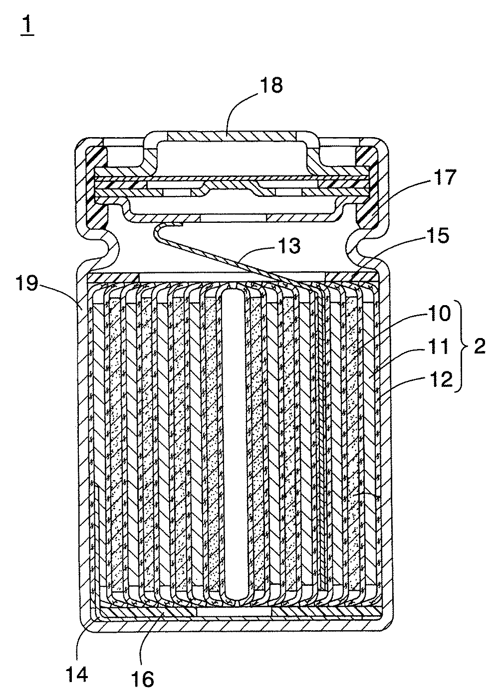
表1から、比較例1の正極板は厚さ増加量が顕著に大きいことが分かる。比較例1の正極板では、正極活物質層に含有されているバインダが、絶縁層ペーストに含有されている有機溶媒に対して高い溶解性を示す。このため、正極活物質層の表面に絶縁層ペーストを塗布する際に、バインダが有機溶媒により膨潤し、厚さ増加量が大きくなったものと考えられる。また、比較例1の正極板にシリンジにてNMPを滴下すると、NMPが瞬時に正極板に浸透する様子が観察された。また、厚さ増加量が大きいことから、電極群の径が大きくなり過ぎ、電極群を電池ケースに挿入することができず、電池を作製することができなかった。 From Table 1, it can be seen that the positive electrode plate of Comparative Example 1 has a significantly large increase in thickness. In the positive electrode plate of Comparative Example 1, the binder contained in the positive electrode active material layer exhibits high solubility in the organic solvent contained in the insulating layer paste. For this reason, it is considered that when the insulating layer paste was applied to the surface of the positive electrode active material layer, the binder was swollen by the organic solvent, and the increase in thickness was increased. Moreover, when NMP was dripped at the positive electrode plate of Comparative Example 1 with a syringe, it was observed that NMP instantaneously permeates the positive electrode plate. Further, since the thickness increase amount is large, the diameter of the electrode group becomes too large, and the electrode group cannot be inserted into the battery case, and the battery cannot be manufactured.
一方、実施例1〜6の正極板では、厚さ増加量が小さく、初期容量の低下が少ないことが分かる。これは、正極板をアニール処理することにより、バインダが結晶化し、溶媒による膨潤が抑制されたためと考えられる。しかしながら、アニール処理を行ったとしても、比較例2、3のように、アニールの処理温度が低いかまたは処理時間が短いと、厚さ増加量が大きい。これはバインダの結晶化が進行していないためと考えられる。 On the other hand, in the positive electrode plates of Examples 1 to 6, it can be seen that the amount of increase in thickness is small and the decrease in initial capacity is small. This is presumably because the binder crystallized by annealing the positive electrode plate, and swelling due to the solvent was suppressed. However, even if the annealing process is performed, as in Comparative Examples 2 and 3, if the annealing process temperature is low or the processing time is short, the thickness increase amount is large. This is probably because the crystallization of the binder has not progressed.
また、実施例7、8のように、アニールの処理時間が長すぎるかまたはアニール処理温度が高すぎると、正極板の厚さ増加量が小さくかつNMP浸透性も良好であるが、電池の初期容量が少し低下する。これは、アニール処理を過度に行うと、バインダが活物質を被覆する面積が大きくなるためであると考えられる。
なお、上記実施例では円筒型電池を用いたが、角型などの形状の電池を用いても同様の効果が得られる。
Further, as in Examples 7 and 8, if the annealing time is too long or the annealing temperature is too high, the amount of increase in the thickness of the positive electrode plate is small and the NMP permeability is good, but the initial battery The capacity drops a little. This is considered to be because if the annealing process is excessively performed, the area where the binder covers the active material increases.
In addition, although the cylindrical battery was used in the said Example, the same effect is acquired even if it uses batteries, such as a square shape.
本発明の非水系二次電池は、高い安全性と優れた電池特性に優とを併せ持っている。したがって、本発明の非水系二次電池は各種電子機器、高出力を要求される電力貯蔵用機器、電気自動車などの電源として有用である。電子機器には、たとえば、ノートブック型パーソナルコンピュータ、携帯電話、デジタルスチルカメラ、携帯用情報端末などがある。 The non-aqueous secondary battery of the present invention has both excellent safety and excellent battery characteristics. Therefore, the non-aqueous secondary battery of the present invention is useful as a power source for various electronic devices, power storage devices that require high output, and electric vehicles. Examples of the electronic device include a notebook personal computer, a mobile phone, a digital still camera, and a portable information terminal.
1 非水系二次電池
2 捲回型電極群
10 正極
11 負極
12 セパレータ
13 正極リード
14 負極リード
15 上部絶縁板
16 下部絶縁板
17 ガスケット
18 封口板
19 電池ケース
DESCRIPTION OF
Claims (5)
活物質層は、集電体表面に形成されかつ活物質およびアニール処理により少なくとも一部が結晶化されたバインダを含有し、アニール処理は活物質層を145℃以上の温度で加熱することにより行われ、
多孔質絶縁層は、活物質層に含有されるバインダの少なくとも一部がアニール処理により結晶化された後に活物質層表面に形成される非水系二次電池用電極。 Including a current collector, an active material layer and a porous insulating layer;
The active material layer contains a binder formed on the surface of the current collector and crystallized at least partly by the active material and the annealing treatment. The annealing treatment is performed by heating the active material layer at a temperature of 145 ° C. or higher. I,
The porous insulating layer is a non-aqueous secondary battery electrode formed on the surface of the active material layer after at least a part of the binder contained in the active material layer is crystallized by annealing.
活物質層形成工程では、活物質およびバインダを含有する活物質層を集電体の表面に形成し、
結晶化工程では、活物質層に含有されるバインダの少なくとも一部をアニール処理により結晶化し、
絶縁層形成工程では、活物質層の表面に多孔質絶縁層を形成する非水系二次電池用電極の製造方法。 Including an active material layer forming step, a crystallization step, and an insulating layer forming step,
In the active material layer forming step, an active material layer containing an active material and a binder is formed on the surface of the current collector,
In the crystallization step, at least a part of the binder contained in the active material layer is crystallized by annealing,
In the insulating layer forming step, a method for producing an electrode for a non-aqueous secondary battery, wherein a porous insulating layer is formed on the surface of the active material layer.
Priority Applications (1)
| Application Number | Priority Date | Filing Date | Title |
|---|---|---|---|
| JP2008323835A JP2010146887A (en) | 2008-12-19 | 2008-12-19 | Electrode for nonaqueous secondary battery and method of manufacturing the same, and nonaqueous secondary battery |
Applications Claiming Priority (1)
| Application Number | Priority Date | Filing Date | Title |
|---|---|---|---|
| JP2008323835A JP2010146887A (en) | 2008-12-19 | 2008-12-19 | Electrode for nonaqueous secondary battery and method of manufacturing the same, and nonaqueous secondary battery |
Publications (1)
| Publication Number | Publication Date |
|---|---|
| JP2010146887A true JP2010146887A (en) | 2010-07-01 |
Family
ID=42567073
Family Applications (1)
| Application Number | Title | Priority Date | Filing Date |
|---|---|---|---|
| JP2008323835A Pending JP2010146887A (en) | 2008-12-19 | 2008-12-19 | Electrode for nonaqueous secondary battery and method of manufacturing the same, and nonaqueous secondary battery |
Country Status (1)
| Country | Link |
|---|---|
| JP (1) | JP2010146887A (en) |
Cited By (3)
| Publication number | Priority date | Publication date | Assignee | Title |
|---|---|---|---|---|
| KR20160138959A (en) * | 2014-04-02 | 2016-12-06 | 니폰 제온 가부시키가이샤 | Positive electrode for secondary cell, method for manufacturing positive electrode secondary cell, and secondary cell |
| WO2023130910A1 (en) * | 2022-01-04 | 2023-07-13 | 宁德时代新能源科技股份有限公司 | Battery electrode sheet manufacturing method, battery electrode sheet, and secondary battery |
| US12015155B2 (en) | 2019-02-01 | 2024-06-18 | Samsung Sdi Co., Ltd. | Compositions for forming a porous insulating layer, electrode for non-aqueous electrolyte rechargeable battery, rechargeable battery including the electrode and method of manufacturing the electrode |
-
2008
- 2008-12-19 JP JP2008323835A patent/JP2010146887A/en active Pending
Cited By (4)
| Publication number | Priority date | Publication date | Assignee | Title |
|---|---|---|---|---|
| KR20160138959A (en) * | 2014-04-02 | 2016-12-06 | 니폰 제온 가부시키가이샤 | Positive electrode for secondary cell, method for manufacturing positive electrode secondary cell, and secondary cell |
| KR101993811B1 (en) * | 2014-04-02 | 2019-06-27 | 니폰 제온 가부시키가이샤 | Positive electrode for secondary cell, method for manufacturing positive electrode secondary cell, and secondary cell |
| US12015155B2 (en) | 2019-02-01 | 2024-06-18 | Samsung Sdi Co., Ltd. | Compositions for forming a porous insulating layer, electrode for non-aqueous electrolyte rechargeable battery, rechargeable battery including the electrode and method of manufacturing the electrode |
| WO2023130910A1 (en) * | 2022-01-04 | 2023-07-13 | 宁德时代新能源科技股份有限公司 | Battery electrode sheet manufacturing method, battery electrode sheet, and secondary battery |
Similar Documents
| Publication | Publication Date | Title |
|---|---|---|
| JP5313761B2 (en) | Lithium ion battery | |
| US8877377B2 (en) | Cathode active material, cathode, and non-aqueous electrolyte secondary battery | |
| JP3797197B2 (en) | Nonaqueous electrolyte secondary battery | |
| JP6258641B2 (en) | Non-aqueous electrolyte secondary battery | |
| JP5264099B2 (en) | Nonaqueous electrolyte secondary battery | |
| JP5264271B2 (en) | Non-aqueous electrolyte secondary battery and manufacturing method thereof | |
| JP5173181B2 (en) | Lithium ion secondary battery and method for producing negative electrode plate for lithium ion secondary battery | |
| EP1711971A1 (en) | Electrode additives coated with electro conductive material and lithium secondary comprising the same | |
| JP2012109123A (en) | Heat-resistant microporous film and separator for batteries | |
| JP2008300302A (en) | Nonaqueous electrolyte secondary battery and method for producing positive electrode for nonaqueous electrolyte secondary battery | |
| JP6687223B2 (en) | Lithium secondary battery | |
| JP5325227B2 (en) | Non-aqueous electrolyte secondary battery electrode plate, method for producing the same, and non-aqueous electrolyte secondary battery | |
| JPWO2006134684A1 (en) | Lithium secondary battery | |
| JPWO2010134258A1 (en) | Electrode plate for non-aqueous electrolyte secondary battery and non-aqueous electrolyte secondary battery | |
| CN102523761A (en) | Nonaqueous electrolyte for secondary battery and nonaqueous electrolyte secondary battery | |
| JP2023507825A (en) | Alkali metal electrode and its manufacturing method | |
| US9190647B2 (en) | Nonaqueous electrolyte secondary battery with high temperature and storage characteristics | |
| JP2013131427A (en) | Laminated battery | |
| US12278376B2 (en) | Method of preparing positive electrode active material for lithium secondary battery and positive electrode active material prepared by the same | |
| JP3501113B2 (en) | Non-aqueous secondary battery and method of manufacturing the same | |
| JP2019164965A (en) | Lithium ion secondary battery | |
| WO2012101693A1 (en) | Negative electrode collector for lithium ion batteries, and lithium ion battery | |
| JP4849291B2 (en) | Secondary battery | |
| JP2010010093A (en) | Manufacturing method of secondary battery electrode group and secondary battery | |
| US20260066259A1 (en) | Method Of Preparing Electrode For Secondary Battery |