JP2010146946A - Luminaire with reflecting mirror - Google Patents
Luminaire with reflecting mirror Download PDFInfo
- Publication number
- JP2010146946A JP2010146946A JP2008325679A JP2008325679A JP2010146946A JP 2010146946 A JP2010146946 A JP 2010146946A JP 2008325679 A JP2008325679 A JP 2008325679A JP 2008325679 A JP2008325679 A JP 2008325679A JP 2010146946 A JP2010146946 A JP 2010146946A
- Authority
- JP
- Japan
- Prior art keywords
- reflecting mirror
- discharge lamp
- central axis
- hole
- axis
- Prior art date
- Legal status (The legal status is an assumption and is not a legal conclusion. Google has not performed a legal analysis and makes no representation as to the accuracy of the status listed.)
- Withdrawn
Links
Images

Landscapes
- Non-Portable Lighting Devices Or Systems Thereof (AREA)
Abstract
【課題】 放電灯と反射鏡を用いる照明器具において、放電灯から出射する色むらを十分に除去することができ、照射面の色ばらつきを抑制する。
【解決手段】 照明器具1は、反射鏡2に設けられた孔部に挿通させる高輝度放電灯4を備え、前記孔部は、反射鏡2の中心軸を法線とする箇所と、該中心軸と交差する軸を法線とする箇所とに設けられていて、反射鏡2の中心軸が略水平に据付けられる場合には、高輝度放電灯4を、反射鏡2の中心軸と交差する軸を法線とする孔部に挿通させ、高輝度放電灯4の長手方向を略鉛直にした状態で使用することができる。これにより、高輝度放電灯4の沈殿物を電極付近に集めることができ、沈殿物を介して出射される光束も少なくなり、色ばらつきを抑制することができる。また、反射鏡2の中心軸が略鉛直に据付けられる場合には、高輝度放電灯4を、反射鏡2の中心軸を法線とする孔部に挿通させる。
【選択図】図4PROBLEM TO BE SOLVED: To sufficiently remove color unevenness emitted from a discharge lamp in a lighting fixture using a discharge lamp and a reflecting mirror, and to suppress color variation of an irradiated surface.
A luminaire includes a high-intensity discharge lamp that is inserted into a hole provided in a reflecting mirror. The hole includes a position having a central axis of the reflecting mirror as a normal and the center. When the central axis of the reflecting mirror 2 is installed substantially horizontally, the high-intensity discharge lamp 4 intersects with the central axis of the reflecting mirror 2. The high-intensity discharge lamp 4 can be used in a state where the longitudinal direction of the high-intensity discharge lamp 4 is made substantially vertical by being inserted through a hole having an axis as a normal line. Thereby, the deposit of the high-intensity discharge lamp 4 can be collected in the vicinity of the electrode, the amount of light emitted through the deposit is reduced, and color variation can be suppressed. When the central axis of the reflecting mirror 2 is installed substantially vertically, the high-intensity discharge lamp 4 is inserted through a hole having the normal axis as the central axis of the reflecting mirror 2.
[Selection] Figure 4
Description
本発明は、放電灯と反射鏡を用いたスポット照明に適した照明器具に関する。 The present invention relates to a lighting fixture suitable for spot lighting using a discharge lamp and a reflecting mirror.
従来の、この種の反射鏡付き照明器具としては、店舗、美術館等でのディスプレイ用のスポットライトがある。また、このスポットライトの光源には、高輝度・高演色性から高輝度放電灯(HIDランプ)が用いられている。このHIDは、発光管内部に封入されたヨウ化物等の揮発状態にないハロゲン化物が発光管の重力方向側の内面に沈殿する。この沈殿物は、通常、黄色みを有していて、ランプからの光は当該沈殿物を介して出射されるため、黄色みを帯びた光が出射されることとなる。そして、この黄色みを帯びた光は反射鏡で反射して、被照射面に到達する。 As a conventional lighting fixture with a reflector of this type, there is a spotlight for display in a store, a museum, or the like. As a light source for the spotlight, a high-intensity discharge lamp (HID lamp) is used because of its high luminance and high color rendering properties. In the HID, halides such as iodide sealed in the arc tube are not volatilized and precipitate on the inner surface of the arc tube on the gravity direction side. This precipitate usually has a yellowish color, and light from the lamp is emitted through the precipitate, so that a yellowish light is emitted. Then, the yellowish light is reflected by the reflecting mirror and reaches the irradiated surface.
このように、沈殿物を介して照射された光が被照射面に照射されると、被照射面を部分的に照射するため、被照射面において部分的に黄色みを帯びることで、色むらが生じ、従って、均斉のとれた照明効果を得ることが難しくなる。 In this way, when the irradiated surface is irradiated with the light irradiated through the deposit, the irradiated surface is partially irradiated. Therefore, it becomes difficult to obtain a uniform lighting effect.
この課題に着目した従来技術として、(1)ランプを改善する(例えば特許文献1参照)、(2)別途装置を用いる(例えば特許文献2参照)、(3)反射鏡に凹凸を付ける(例えば特許文献3参照)、といった解決手段がある。
特許文献1に示される技術においては、ランプ発光管内壁にフロスト部を設けることによって、色むらを少なくするようにしているが、色むらを十分に除去できていない。
As prior arts focusing on this problem, (1) improving the lamp (for example, see Patent Document 1), (2) using a separate device (for example, see Patent Document 2), and (3) making the reflecting mirror uneven (for example, There is a solution such as (see Patent Document 3).
In the technique disclosed in
特許文献2に示される技術においては、ランプを管軸中心に回転させながら点灯することで、発光管内壁の温度が一定となり、沈殿物を蒸発させることにより、色むらを除去している。ところが、この技術では、装置が大型化し、コスト増となる。
In the technique disclosed in
特許文献3に示される技術においては、リフレクタに微小な凹凸を設けたことで、この微小な凹凸で反射される光は適宜に散乱されて混じり合うので、反射光は白色に近くなる。ところが、この技術においては、狭角配光で色むらは改善されるが、広角配光では改善されない。
本発明は、上記のような従来技術の問題を解消するものであり、放電灯と反射鏡を用いる照明器具において、放電灯から出射する色むらを十分に除去することができ、照射面の色ばらつきを抑制することができる反射鏡付き照明器具を提供することを目的とする。 The present invention solves the problems of the prior art as described above, and in a lighting fixture using a discharge lamp and a reflecting mirror, it is possible to sufficiently remove the color unevenness emitted from the discharge lamp, and the color of the irradiated surface. It aims at providing the lighting fixture with a reflecting mirror which can suppress dispersion | variation.
請求項1の発明は、開放縁と、この開放縁の中心に直交する中心軸を回転軸とする反射面とを有する反射鏡と、この反射鏡を収容する筐体と、前記反射鏡に設けられた孔部に挿通させて前記筐体に装着される高輝度放電灯と、を備えた反射鏡付き照明器具であって、前記孔部は、前記中心軸を法線とする箇所と、前記中心軸と交差する軸を法線とする箇所とに設けられているものである。 According to a first aspect of the present invention, there is provided a reflecting mirror having an open edge and a reflecting surface having a central axis orthogonal to the center of the open edge as a rotation axis, a housing for housing the reflecting mirror, and the reflecting mirror. A high-intensity discharge lamp that is inserted into the hole and attached to the housing, and the hole includes a portion having the central axis as a normal line, It is provided at a location having an axis intersecting the central axis as a normal line.
請求項2の発明は、請求項1に記載の反射鏡付き照明器具において、前記孔部は、前記中心軸を法線とする箇所と、前記中心軸と交差する軸を法線とする箇所とが連続する長孔として設けられているものである。
The invention according to
請求項1の発明によれば、反射鏡の中心軸が略水平に据付けられる場合には、高輝度放電灯を、反射鏡の中心軸と交差する軸を法線とする孔部に挿通させることで、高輝度放電灯の長手方向を略鉛直にした状態で使用することができる。これにより、高輝度放電灯の沈殿物を電極付近に集めることができ、電極付近を通過して照射される光束が少ないことから、沈殿物を介して出射される光束も少なくなり、色ばらつきを抑制することができる。また、反射鏡の中心軸が略鉛直に据付けられる場合には、高輝度放電灯を、反射鏡の中心軸を法線とする孔部に挿通させることで、上記と同等の作用効果が得られる。 According to the first aspect of the present invention, when the central axis of the reflecting mirror is installed substantially horizontally, the high-intensity discharge lamp is inserted into the hole whose normal is the axis that intersects the central axis of the reflecting mirror. Thus, the high-intensity discharge lamp can be used in a state where the longitudinal direction is substantially vertical. As a result, the deposits of the high-intensity discharge lamp can be collected near the electrodes, and the amount of light emitted through the vicinity of the electrodes is small. Can be suppressed. Further, when the central axis of the reflecting mirror is installed substantially vertically, the same effect as described above can be obtained by inserting the high-intensity discharge lamp through the hole having the normal axis as the central axis of the reflecting mirror. .
請求項2の発明によれば、反射鏡の任意の据付角に対しても、高輝度放電灯の長手方向を略鉛直にした状態で使用することができ、色ばらつきを抑制することができる。
According to invention of
(第1の実施形態)
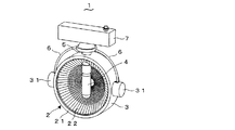
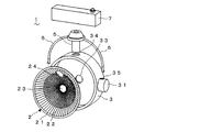
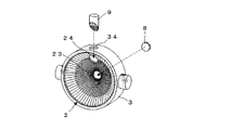
本発明の第1の実施形態に係る反射鏡付き照明器具1について図1乃至図4を参照して説明する。図1は照明器具1の反射鏡2の中心軸が略水平に据付けられる場合を示し、図2はその分解状態を示す。照明器具1は、反射鏡2と、この反射鏡2を収容する筐体3と、筐体3に装着されるHIDランプ等の高輝度放電灯4(以下、放電灯と略記する)と、を備えている。また、筐体3には、アーム部6及びソケット部5を介して安定器7が取り付けられている。
(First embodiment)
A
ソケット部5は、筐体3に設けられた孔部34(又は33)、さらには、反射鏡2の孔部24(又は23)を挿通して反射鏡2内に臨み、放電灯4の口金を装着可能としている。なお、本明細書では、このように放電灯4が、筐体3の孔部34(又は33)及び反射鏡2の孔部24(又は23)を挿通させたソケット部5を介して筐体3に装着されることを、放電灯4が反射鏡2の孔部24(又は23)を挿通して筐体3に装着される、と略記している。
The
反射鏡2は、開放縁21と、この開放縁21の中心に直交する中心軸を回転軸とする断面略放物線形状の反射面22とを有する。反射鏡2には、放電灯4(ソケット部5)が挿通される孔部23,24が設けられている。孔部23は、前記中心軸を法線とする箇所に設けられたものであり、孔部24は、前記中心軸と交差する軸を法線とする箇所に設けられたものである。なお、反射鏡2の反射面22の表面に凹凸形状があることで、散光効果が得られ、照射面の均斉度が上がる。
The reflecting
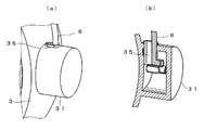
筐体3は、反射鏡2を固定し、保護するに必要な強度を持つ、樹脂、金属などの加工性が良い材料が好ましい。筐体3には、反射鏡2と同様に、孔部が、中心軸を法線とする箇所(33)と、中心軸と交差する軸を法線とする箇所(34)と、に設けられている。また、図3に示すように、筐体3の側面には、アーム連結用突部31が設けられ、この突部31には穴35が設けられていて、この穴35にアーム部6の端部が結合されるようになっている。アーム部6は、筐体3と安定器7を結合するもので、樹脂・金属などの部材で成り、図3に示した連結構造の場合、アーム部6を押し曲げる必要があるので、伸縮性を持つことが望ましい。
The
放電灯4は、透光性を有するセラミック製の容器内部に形成されている放電空間に一対の電極部が保持されるとともに、放電空間に希ガス及びハロゲン化物が封入された発光管を備えた、所謂セラミックメタルハライドランプを用いる。安定器7は、交流電源からの電圧・電流を照明光源に適した値に変換するものである。
The
この種の放電灯4は、発光により発光管内に沈殿物が発生し、照射光に影響を及ぼすことがあることから、鉛直方向に固定して設置して、その影響を少なくすることが望ましい。そこで、図1に示されるように、反射鏡2の中心軸が略水平に据付けられる場合には、放電灯4を反射鏡2の孔部24に挿通させることで、放電灯4の長手方向を略鉛直にした状態で使用することができる。
Since this kind of
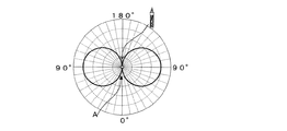
ここで、図5及び図6を参照して、放電灯4の配光曲線について説明する。図5は放電灯4の構成を示し、図6は放電灯4が鉛直配置状態での縦断面での配光曲線を示す。図5に示されるように、放電灯4は、発光管41と、その周囲の内外二重管42と、口金43を有し、発光管41の上下に電極がある。発光管41の発光部から出射される光のうち、電極付近を通過して外部に照射される光線は、その電極が影となり光束が少なくなる。このため、配光曲線は、図6に示されるように、上方及び下方(Aで示す)の光度が弱い。
Here, with reference to FIG.5 and FIG.6, the light distribution curve of the
従って、本実施形態のように、放電灯4を鉛直方向に設置した状態で使用すれば、沈殿物を電極付近に集めることができ、電極付近を通過して外部に照射される光束が少ないことから、沈殿物を介して外部に出射される黄色みを帯びた光束も少なくなる。その結果、照射面に色むらが発生しなくなる。
Therefore, if the
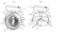
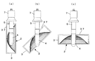
図4(a)(b)は、本実施形態の照明器具1において反射鏡2の据付け方向が回転された場合を示す。図4(a)は上述した図1と同じ状態、すなわち、反射鏡2の中心軸が略水平に据付けられる場合であり、図4(b)は反射鏡2の中心軸が略垂直に据付けられる場合を示す。図4(b)では、放電灯4(ソケット部5)を、反射鏡2の孔部23、筐体3の孔部33に挿通させることで、放電灯4の長手方向を略鉛直にしたまま使用することができる。このように、反射鏡2の据付け方向に係わらず、放電灯4の設置方向は鉛直方向とすることができ、コンパーチブルなものとなる。なお、アーム連結用突部31の穴は、図4(a)(b)のいずれでもアーム部6を結合できるように複数位置に設けられていて、適宜にアーム部6の連結位置を変更する。
4A and 4B show a case where the installation direction of the reflecting
図7は、本実施形態の照明器具1に使用される補助反射部材8,9を示す。反射鏡2及び筐体3の設置方向によって、放電灯4が挿通されていない孔部が常に存在する。この孔部から光が漏れ出し、グレアとなり、又は器具の動作効率が低下してしまう。補助反射部材8,9は、これらを防ぐためのもので、孔部に収まり孔部を隙間なく塞ぐ反射部材である。
FIG. 7 shows the
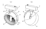
(第2の実施形態)
本発明の第2の実施形態に係る照明器具1について図8及び図9を参照して説明する。これらの図に示されるように、本実施形態の照明器具1においては、反射鏡2及び筐体3に、これらを回転し得るように、放電灯4(ソケット部5)が挿通される連続した長い孔部37が設けられている。孔部37は、反射鏡2の中心軸を法線とする箇所と、中心軸と直交する軸を法線とする箇所とが連続する長孔として設けられている。さらに、アーム部6は、筐体3が回転自在となるように、片持ちにて筐体3とソケット部5とを連結し、アーム部6の筐体3との結合部には、筐体3を回転自在とする機構を備えている。これらの構成により、反射鏡2及び筐体3が回転自在となる。
(Second Embodiment)
The
本実施形態においては、反射鏡2が回転自在であるため、簡単に光照射方向を変えることができる。また、反射鏡2を任意の角度に回転させても、放電灯4の長手方向を略鉛直にしたまま使用することができる。従って、第1の実施形態と同様に、照射面に色むらが発生しなくなる効果が得られる。
In the present embodiment, since the reflecting
本発明は、上記実施形態の構成に限られず、種々の変更が可能であり、例えば、上記実施形態では、筐体3が反射鏡2の背面の全てを覆い収容する形状のものを示したが、背面の全てを覆うことなく、例えば、反射鏡2の開放縁21の一部周囲に沿う枠のような形状であっても構わない。また、アーム部6は必要に応じて用いればよく、また、安定器7の取り付け位置は任意に選択することができる。
The present invention is not limited to the configuration of the above embodiment, and various modifications are possible. For example, in the above embodiment, the
1 照明器具
2 反射鏡
21 開放縁
22 反射面
23、24 反射鏡2の孔部
3 筐体
4 高輝度放電灯
DESCRIPTION OF
Claims (2)
前記孔部は、前記中心軸を法線とする箇所と、前記中心軸と交差する軸を法線とする箇所とに設けられていることを特徴とする反射鏡付き照明器具。 A reflecting mirror having an open edge and a reflecting surface having a central axis orthogonal to the center of the open edge as a rotation axis, a housing for housing the reflecting mirror, and a hole provided in the reflecting mirror A high-intensity discharge lamp mounted on the housing, and a reflector-equipped lighting fixture comprising:
The said lighting part is provided in the location which makes the said central axis a normal line, and the location which makes the axis | shaft which cross | intersects the said central axis a normal line, The lighting fixture with a reflector characterized by the above-mentioned.
Priority Applications (1)
| Application Number | Priority Date | Filing Date | Title |
|---|---|---|---|
| JP2008325679A JP2010146946A (en) | 2008-12-22 | 2008-12-22 | Luminaire with reflecting mirror |
Applications Claiming Priority (1)
| Application Number | Priority Date | Filing Date | Title |
|---|---|---|---|
| JP2008325679A JP2010146946A (en) | 2008-12-22 | 2008-12-22 | Luminaire with reflecting mirror |
Publications (1)
| Publication Number | Publication Date |
|---|---|
| JP2010146946A true JP2010146946A (en) | 2010-07-01 |
Family
ID=42567121
Family Applications (1)
| Application Number | Title | Priority Date | Filing Date |
|---|---|---|---|
| JP2008325679A Withdrawn JP2010146946A (en) | 2008-12-22 | 2008-12-22 | Luminaire with reflecting mirror |
Country Status (1)
| Country | Link |
|---|---|
| JP (1) | JP2010146946A (en) |
Cited By (2)
| Publication number | Priority date | Publication date | Assignee | Title |
|---|---|---|---|---|
| CN104456212A (en) * | 2014-12-09 | 2015-03-25 | 苏州科利亚照明科技有限公司 | Directional illuminating lamp |
| KR20180064109A (en) * | 2016-12-05 | 2018-06-14 | 양평섭 | Spotlight device |
-
2008
- 2008-12-22 JP JP2008325679A patent/JP2010146946A/en not_active Withdrawn
Cited By (2)
| Publication number | Priority date | Publication date | Assignee | Title |
|---|---|---|---|---|
| CN104456212A (en) * | 2014-12-09 | 2015-03-25 | 苏州科利亚照明科技有限公司 | Directional illuminating lamp |
| KR20180064109A (en) * | 2016-12-05 | 2018-06-14 | 양평섭 | Spotlight device |
Similar Documents
| Publication | Publication Date | Title |
|---|---|---|
| JP4080543B2 (en) | lighting equipment | |
| CA2247233C (en) | Triple tube scoop lighting fixture | |
| US8680756B2 (en) | Optical system for a luminaire | |
| JP5010433B2 (en) | lighting equipment | |
| JP2010146946A (en) | Luminaire with reflecting mirror | |
| JP2001076505A (en) | Lighting equipment | |
| JP4787610B2 (en) | High pressure discharge lamp with a base on one side | |
| JP4465113B2 (en) | lighting equipment | |
| JP4989696B2 (en) | Wall washer-type lighting fixture | |
| JP4736965B2 (en) | Tunnel lighting | |
| CN1251663A (en) | Lighting device for projector | |
| US7621649B2 (en) | Light distribution control type Illuminator | |
| JP5313059B2 (en) | lighting equipment | |
| JP2006120426A (en) | lighting equipment | |
| JP4577273B2 (en) | Lighting equipment for high-intensity discharge lamps | |
| CN103843108B (en) | Metal halide lamp and the headlamp with described lamp for car headlamp | |
| JP5032816B2 (en) | Tunnel lighting method | |
| JP4577454B2 (en) | Lighting equipment for high-intensity discharge lamps | |
| JP4577453B2 (en) | Lighting equipment for high-intensity discharge lamps | |
| JP4334283B2 (en) | Display shelf lighting | |
| KR200350543Y1 (en) | the light coated a light-reflective material | |
| JP4923034B2 (en) | Fluorescent lamp | |
| JP5122913B2 (en) | lighting equipment | |
| JP2007073461A (en) | High intensity discharge lamp or high intensity discharge lamp with reflector | |
| JP2001216801A (en) | Closed lighting equipment |
Legal Events
| Date | Code | Title | Description |
|---|---|---|---|
| A300 | Withdrawal of application because of no request for examination |
Free format text: JAPANESE INTERMEDIATE CODE: A300 Effective date: 20120306 |