JP2010162995A - Seat belt device - Google Patents
Seat belt device Download PDFInfo
- Publication number
- JP2010162995A JP2010162995A JP2009005858A JP2009005858A JP2010162995A JP 2010162995 A JP2010162995 A JP 2010162995A JP 2009005858 A JP2009005858 A JP 2009005858A JP 2009005858 A JP2009005858 A JP 2009005858A JP 2010162995 A JP2010162995 A JP 2010162995A
- Authority
- JP
- Japan
- Prior art keywords
- seat
- webbing
- occupant
- bag body
- fluid
- Prior art date
- Legal status (The legal status is an assumption and is not a legal conclusion. Google has not performed a legal analysis and makes no representation as to the accuracy of the status listed.)
- Granted
Links
- 239000012530 fluid Substances 0.000 claims abstract description 77
- 238000009423 ventilation Methods 0.000 claims description 6
- 230000000452 restraining effect Effects 0.000 claims description 3
- 239000000463 material Substances 0.000 description 23
- 230000003014 reinforcing effect Effects 0.000 description 5
- 230000002093 peripheral effect Effects 0.000 description 4
- 230000000694 effects Effects 0.000 description 3
- 230000001133 acceleration Effects 0.000 description 2
- 230000015572 biosynthetic process Effects 0.000 description 2
- 238000001514 detection method Methods 0.000 description 2
- 230000002787 reinforcement Effects 0.000 description 2
- 238000013459 approach Methods 0.000 description 1
- 239000007788 liquid Substances 0.000 description 1
- 230000004048 modification Effects 0.000 description 1
- 238000012986 modification Methods 0.000 description 1
- 230000000149 penetrating effect Effects 0.000 description 1
Images






Landscapes
- Automotive Seat Belt Assembly (AREA)
Abstract
Description
本発明は、ウエビングベルトによって車両のシートに着座した乗員の身体を拘束するシートベルト装置に関する。 The present invention relates to a seat belt device for restraining the body of an occupant seated on a vehicle seat by a webbing belt.
下記特許文献1に開示されたシートベルト装置では、シートの幅方向を軸方向とする軸周りに回動可能に設けられたシートベルト装置のバックルをシートの背もたれ部に形成した格納部に格納している。また、このシートベルト装置では、シートのシート部に可撓性を有する長尺のパウル作動部材を配置している。パウル作動部材の先端はパウルに繋がっており、乗員がシート部に着座した際の荷重でパウル作動部材がパウルを引っ張ってパウルを回動させると、ロック部材と支持レバーの係合凹部との係合が解消される。 In the seatbelt device disclosed in Patent Document 1 below, the buckle of the seatbelt device provided so as to be rotatable around an axis whose axial direction is the width direction of the seat is stored in a storage portion formed in the backrest portion of the seat. ing. Further, in this seat belt device, a long pawl operating member having flexibility is disposed in the seat portion of the seat. The front end of the pawl operating member is connected to the pawl. The match is resolved.
これにより、支持レバーがスプリングの付勢力で回動すると、支持レバーの先端に取り付けられたバックルが格納部から抜け出る。このように、乗員がシート部に着座した際には、背もたれ部に形成した格納部からバックルが抜け出るので乗員はウエビングベルトに設けられたタングを容易にバックルに装着でき、また、乗員がシート部に着座していない状態では背もたれ部に形成した格納部にバックルが格納されているので、乗員がシート部に着座するに際してバックルが乗員の身体に干渉しにくい。 Thereby, when the support lever is rotated by the biasing force of the spring, the buckle attached to the tip of the support lever comes out of the storage portion. Thus, when the occupant sits on the seat part, the buckle comes out of the storage part formed in the backrest part, so the occupant can easily attach the tongue provided on the webbing belt to the buckle, and the occupant can When the seat is not seated on the seat, the buckle is stored in the storage portion formed on the backrest portion, so that the buckle hardly interferes with the body of the passenger when the passenger sits on the seat portion.
一方、下記特許文献2に開示された乗物用シートを構成するシートバックには、可動部材がシートバックの前方側へスライド可能に設けられている。また、シートバックにはエアポンプと駆動モータが設けられており、シートクッションに設けられた圧力センサが、シートクッションに乗員が着座したことを検知すると、駆動モータが作動し、駆動モータの駆動力でエアポンプが作動する。エアポンプから送られたエアは、シート前方に空気袋が伸びるように空気袋を膨張させる。 On the other hand, the seat back constituting the vehicle seat disclosed in Patent Document 2 below is provided with a movable member slidably forward of the seat back. Also, the seat back is provided with an air pump and a drive motor. When the pressure sensor provided on the seat cushion detects that an occupant is seated on the seat cushion, the drive motor is activated, and the drive force of the drive motor The air pump is activated. The air sent from the air pump inflates the air bag so that the air bag extends in front of the seat.
このようにして膨張した空気袋は上記の可動部材を押圧してシートバックから突出させる。このようにしてシートバックの前方に突出する可動部材の先端にはウエビングベルト(アウタベルト)が接しており、可動部材がシートバックの前方に突出することで、ウエビングベルトの可動部材との当接部分がシートバックの前面から前方へ離間するように移動する。 The air bag inflated in this manner presses the movable member and protrudes from the seat back. The webbing belt (outer belt) is in contact with the tip of the movable member protruding in front of the seat back in this way, and the movable member protrudes in front of the seat back, so that the webbing belt is in contact with the movable member. Moves away from the front of the seat back.
このようにウエビングベルトの一部が前方へ移動することで、シートに着座した乗員はウエビングベルトを容易に掴むことができ、ひいては、ウエビングベルトを容易に装着できる。しかも、シートに乗員が着座していない状態では、可動部材はシートバックに格納され、ウエビングベルトはシートバックの前面に接しているので、乗員がシート部に着座するに際して可動部材やウエビングベルトが乗員の身体に干渉しにくい。 Thus, a part of the webbing belt moves forward, so that an occupant seated on the seat can easily grasp the webbing belt, and thus can easily wear the webbing belt. In addition, when the passenger is not seated on the seat, the movable member is stored in the seat back, and the webbing belt is in contact with the front surface of the seat back. It is hard to interfere with the body.
しかしながら、特許文献1に開示された構成では、乗員がシートに着座するたびにパウル作動部材に荷重がかかるうえ、乗員がシートから離間すればパウル作動部材が元の状態になるように引っ張られる。このため、パウル作動部材は可撓性のほかに荷重や引っ張りに対する充分な耐久性を有していなくては長期に亘る良好な動作性を確保できない。しかも、シートの座面の下側にパウル作動部材や荷重作用部材等を配置している。このような各種部材を配置するため、シートのクッションが薄くなり座り心地が悪くなる。また、このような各種部材を配置しつつもシートのクッションに充分な厚さを確保すると、シートが厚くなってしまう。 However, in the configuration disclosed in Patent Document 1, a load is applied to the pawl operating member every time the occupant sits on the seat, and when the occupant moves away from the seat, the pawl operating member is pulled to the original state. Therefore, the pawl actuating member cannot secure good operability over a long period of time unless it has flexibility and sufficient durability against load and tension. Moreover, a pawl actuating member, a load acting member, and the like are disposed below the seat surface of the seat. Since such various members are arranged, the seat cushion becomes thin and the sitting comfort is deteriorated. Further, if a sufficient thickness is secured for the cushion of the seat while arranging such various members, the seat becomes thick.
一方、特許文献2に開示された構成では、可動部材の押し出しに駆動モータとエアポンプを要するので、コストが高くなる。 On the other hand, in the configuration disclosed in Patent Document 2, a drive motor and an air pump are required to push out the movable member, which increases the cost.
本発明は、上記事実を考慮して、シートに着座した乗員がウエビングベルトを容易に装着でき、しかも、そのための構成を安価なコストで実現でき、長期に亘り良好な動作性を確保できるシートベルト装置を得ることが目的である。 In consideration of the above facts, the present invention allows a passenger seated in a seat to easily attach a webbing belt, and can realize a configuration for the seat belt at a low cost and ensure good operability over a long period of time. The purpose is to obtain a device.
請求項1に記載の本発明に係るシートベルト装置は、シートを構成するシートバックの後方又は下方に設けられて、前記シートにおける乗員の着座位置の側方から前記シートに着座した乗員の身体に装着されることで前記乗員の身体を拘束可能な長尺帯状のウエビングベルトと、前記着座位置の側方で且つ前記シートバックの上側の初期位置に設けられて、前記初期位置を通過する前記ウエビングベルトを支持するウエビング支持体と、前記着座位置の側方の初期位置に設けられて、前記乗員の身体に前記ウエビングベルトが装着される際には前記ウエビングベルトに設けられたタングが装着されるバックルと、前記シートに設けられて前記シートに着座した前記乗員からの荷重で萎んで内部の流体を放出し、この放出した流体の圧力で前記ウエビング支持体及びバックルの少なくとも何れかの一方を、その初期位置に対して所定の向きに離間した装着アシスト位置へ移動させる袋体と、前記袋体の内部に設けられ、前記荷重を受けることで圧縮されると共に前記荷重が解消されることで弾性により復元し、復元することで萎んだ前記袋体を膨らませて前記袋体に流体を吸入させる弾性体と、を備えている。 The seat belt device according to the first aspect of the present invention is provided on the rear or lower side of the seat back constituting the seat, on the body of the occupant seated on the seat from the side of the seating position of the occupant in the seat. A long belt webbing belt capable of restraining the occupant's body by being mounted, and the webbing provided at an initial position on the side of the seating position and above the seat back and passing through the initial position A webbing support for supporting the belt, and a tongue provided on the webbing belt is provided at an initial position on the side of the seating position and when the webbing belt is worn on the occupant's body. A buckle and a load from the occupant seated on the seat provided on the seat are deflated to release an internal fluid, and the pressure of the released fluid A bag body that moves at least one of the ebbing support body and the buckle to a mounting assist position that is spaced in a predetermined direction with respect to the initial position; and a bag body that is provided inside the bag body and receives the load. An elastic body that is compressed and is restored by elasticity when the load is eliminated, and that the bag body that has been deflated by the restoration is inflated to suck the fluid into the bag body.
請求項1に記載の本発明に係るシートベルト装置では、シートに乗員が着座することで袋体に荷重を付与すると、袋体と袋体内の弾性体が萎んで袋体から流体が放出される。袋体から放出された流体の圧力はウエビング支持体及びバックルの少なくとも何れか一方が受けると、その初期位置から所定の向きに離間した装着アシスト位置に移動させられる。 In the seat belt device according to the first aspect of the present invention, when a load is applied to the bag body by an occupant sitting on the seat, the bag body and the elastic body in the bag body are deflated and fluid is released from the bag body. . When the pressure of the fluid discharged from the bag is received by at least one of the webbing support and the buckle, the fluid is moved from the initial position to a mounting assist position spaced apart in a predetermined direction.
ウエビング支持体はシートにおける乗員の着座位置の側方で且つシートを構成するシートバックの上側が初期位置とされており、この初期位置を通過するウエビングベルトを支持している。このウエビング支持体が袋体からの流体の圧力を受けて初期位置から所定の向き、例えば、シート前方側へ離間した装着アシスト位置に移動すると、ウエビング支持体によるウエビングベルトの支持位置が装着アシスト位置の側(例えば、シートの前方側)に変位する。これにより、シートに着座した乗員はウエビングベルトを把持しやすくなり、ウエビングベルトの装着が容易になる。 The webbing support body has an initial position at the side of the seating position of the occupant and the upper side of the seat back constituting the seat, and supports the webbing belt passing through the initial position. When the webbing support receives the pressure of the fluid from the bag and moves from the initial position to a mounting assist position separated from the initial position, for example, toward the seat front side, the webbing belt support position by the webbing support becomes the mounting assist position. (For example, the front side of the seat). As a result, an occupant seated on the seat can easily grip the webbing belt, and the webbing belt can be easily attached.
一方、バックルはシートにおける乗員の着座位置の側方が初期位置とされる。このバックルが袋体からの流体の圧力を受けて初期位置から所定の向き、例えば、シート前方側やシート上方側へ離間した装着アシスト位置に移動すると、シートに着座した乗員はバックルを確認しやすくなると共に、ウエビングベルトに設けられたタングをバックルに装着する際の作業が容易になる。 On the other hand, the buckle has an initial position lateral to the seating position of the occupant. When this buckle receives the pressure of the fluid from the bag body and moves from the initial position to a predetermined orientation, for example, a seating assist position separated from the front side of the seat or the upper side of the seat, the occupant seated on the seat can easily check the buckle. At the same time, the work for attaching the tongue provided on the webbing belt to the buckle becomes easy.
このように、乗員がシートに着座することで、ウエビング支持体及びバックルの少なくとも何れか一方がその初期位置から装着アシスト位置に移動させられるので、ウエビングベルトの装着が容易になる。 Thus, when the occupant is seated on the seat, at least one of the webbing support and the buckle is moved from the initial position to the mounting assist position, so that the webbing belt can be easily mounted.
一方、乗員がシートから離れると、それまで袋体に作用していた荷重が解消される。このように、袋体への荷重が解消されると、袋体と共に萎んでいた弾性体は自らの弾性で圧縮状態から復元し、萎んでいる袋体を内側から膨らませて袋体に流体を吸入させる。これにより、袋体が復元し、乗員が再度シートに着座した際には、その荷重で袋体が萎んで袋体から流体が放出される。 On the other hand, when the occupant leaves the seat, the load that has been applied to the bag body is eliminated. In this way, when the load on the bag body is removed, the elastic body that has withered together with the bag body recovers from its compressed state by its own elasticity, and inflates the deflated bag body from the inside and sucks fluid into the bag body Let Thereby, when the bag body is restored and the occupant sits on the seat again, the bag body is deflated by the load and the fluid is discharged from the bag body.
このように、本発明では、ウエビング支持体及びバックルの少なくとも何れか一方への流体の供給源が袋体であるので、構造が簡単であると共に、荷重センサ等の荷重を電気的に検出する検出手段が不要であるので、更に、構造を簡単にできる。しかも、萎んだ袋体は弾性体の弾性で復元されるので、袋体を復元させるための構成も簡単である。 As described above, according to the present invention, since the fluid supply source to at least one of the webbing support and the buckle is a bag, the structure is simple and the detection is performed to electrically detect the load such as a load sensor. Since no means is required, the structure can be further simplified. In addition, since the deflated bag body is restored by the elasticity of the elastic body, the configuration for restoring the bag body is also simple.
さらに、袋体は乗員の荷重で萎むように変形させられるものの、過剰な引っ張り力が作用するような構成ではなく、しかも、萎んだ状態からの復元は弾性体の弾性であるので、復元の際も過剰な引っ張り力が作用しない。このため、袋体の強度を特別高く設定しなくても、充分な耐久性を袋体は有しており、長期に亘り良好な動作性を確保できる。しかも、この弾性体は、萎んだ袋体を元の形状に復元できればよいので、弾性体にシートのクッションと同等の特性を持たせることができる。このため、袋体や弾性体をシートに設けてもシートが大型化することなく、また、座り心地も悪くなることがない。 Furthermore, although the bag body is deformed so as to wither due to the load of the occupant, it is not a configuration in which excessive tensile force acts, and since restoration from the withered state is the elasticity of the elastic body, Excessive pulling force does not work. For this reason, even if the strength of the bag body is not set to be particularly high, the bag body has sufficient durability, and good operability can be ensured over a long period of time. In addition, since the elastic body only needs to restore the deflated bag body to its original shape, the elastic body can have the same characteristics as the cushion of the seat. For this reason, even if a bag or an elastic body is provided on the seat, the seat does not increase in size and the sitting comfort does not deteriorate.
なお、本発明では、袋体からの流体の圧力により初期位置から装着アシスト位置に移動するのは、ウエビング支持体及びバックルの少なくとも何れか一方であればよい。すなわち、袋体からの流体の圧力により初期位置から装着アシスト位置に移動するのは、ウエビング支持体だけであってもよいし、バックルだけであってもよく、更には、ウエビング支持体及びバックルの双方であってもよい。 In the present invention, the movement from the initial position to the mounting assist position by the pressure of the fluid from the bag body may be at least one of the webbing support and the buckle. That is, only the webbing support or only the buckle may be moved from the initial position to the mounting assist position due to the pressure of the fluid from the bag, and further, the webbing support and the buckle may be moved. Both may be sufficient.
また、本発明では、袋体はシートに着座した乗員からの荷重を受けて流体を放出する構成であるが、袋体が受けるシートに着座した乗員からの荷重は、シートに乗員が着座することでシートを構成するシートクッションが受ける荷重であってもよく、また、シートに着座した乗員がシートバックに凭れ掛かることでシートバックが受ける荷重であってもよい。 Further, in the present invention, the bag body is configured to release a fluid upon receiving a load from an occupant seated on the seat, but the load from the occupant seated on the seat received by the bag body is that the occupant sits on the seat. The load received by the seat cushion constituting the seat may be the load received by the seat back when the occupant seated on the seat leans on the seat back.
さらに、本発明において弾性体は弾性による復元で萎んだ袋体を復元できればよく、その具体的な構成に関しては特に限定されるものではない。しかしながら、弾性体が収容される袋体はシートに設けられて、シートに着座した乗員の荷重を受けて萎むという観点からすると、シートに着座した乗員の身体に対して、弾性体が不要に干渉しないことが好ましい。この意味からすれば、シートなどに適用されるクッション材等が弾性体として好ましい。 Furthermore, in the present invention, the elastic body is not particularly limited as long as the elastic body can restore the deflated bag body by elastic restoration. However, from the standpoint that the bag body in which the elastic body is accommodated is provided on the seat and receives the load of the occupant seated on the seat, the elastic body is unnecessary for the body of the occupant seated on the seat. It is preferable not to interfere. In this sense, a cushion material applied to a seat or the like is preferable as the elastic body.
請求項2に記載の本発明に係るシートベルト装置は、請求項2に記載の本発明において、前記シートを構成するシートクッションに前記袋体を設けると共に、車両急減速状態で作動して前記袋体に流体を供給し、前記袋体を膨張させる流体供給手段を備えている。 A seat belt device according to a second aspect of the present invention is the seat belt device according to the second aspect of the present invention, wherein the bag body is provided on a seat cushion constituting the seat, and the bag is operated in a vehicle sudden deceleration state. Fluid supply means for supplying fluid to the body and inflating the bag body is provided.
請求項2に記載の本発明に係るシートベルト装置では、シートを構成するシートクッションに袋体が設けられる。シートに乗員が着座すると、袋体は乗員からの荷重を受けて萎み、袋体が放出した流体の圧力でウエビング支持体及びバックルの少なくとも何れか一方を、その初期位置から装着アシスト位置に移動させる。 In the seat belt device according to the second aspect of the present invention, the bag body is provided on the seat cushion constituting the seat. When the occupant sits on the seat, the bag body receives the load from the occupant and is deflated, and at least one of the webbing support and the buckle is moved from the initial position to the mounting assist position by the pressure of the fluid discharged from the bag body. Let
このように、乗員が着座することで萎んだ袋体には、車両急減速状態になると流体供給手段から流体が供給される。このように流体供給手段からの流体が袋体に供給されると、萎んでいる袋体が膨張してシートクッションの少なくとも座面を押し上げる。これにより、シートにおける乗員の着座姿勢が強制的に変えられ、ウエビングベルトによる乗員の身体の拘束性が向上する。 As described above, the fluid supplied from the fluid supply means is supplied to the bag body that is deflated when the occupant is seated when the vehicle suddenly decelerates. Thus, when the fluid from the fluid supply means is supplied to the bag body, the deflated bag body expands and pushes up at least the seat surface of the seat cushion. As a result, the seating posture of the occupant on the seat is forcibly changed, and the restraint of the occupant's body by the webbing belt is improved.
請求項3に記載の本発明に係るシートベルト装置は、請求項1又は請求項2に記載の本発明において、前記シートバックの上端部又は当該上端部の後方側で前記シートの上下方向を軸方向とする軸周りに回動可能に設けられると共に、回動中心よりも前記シートの前方側へ向けて先端が開口した前記ウエビング支持体を前記シートバックの上端部又は前記シートバックの後方で車体前記ウエビング支持体及び前記バックルのうち前記袋体から放出された流体の圧力で移動する方と前記袋体とを繋ぎ、前記袋体から放出された流体が通過する管状の第1接続手段と、前記第1接続手段の中間部と前記流体供給手段とを繋ぎ、前記流体供給手段からの流体が通過する管状の第2接続手段と、前記第1接続手段と前記第2接続手段との接続部分に設けられ、通常は前記第1接続手段と前記第2接続手段との間を閉止して前記第1接続手段を開放すると共に、前記車両急減速状態では前記第1接続手段と前記第2接続手段との接続部分と前記ウエビング支持体及び前記バックルのうち前記袋体から放出された流体の圧力で移動する方との間を閉止して前記第1接続手段と前記第2接続手段との接続部分と前記袋体との間を開放する弁と、を備えている。 A seat belt device according to a third aspect of the present invention is the seat belt device according to the first or second aspect of the present invention, wherein the seat belt device is pivoted in the up-down direction of the seat at the upper end portion of the seat back or the rear side of the upper end portion. The webbing support body which is provided so as to be rotatable around an axis in a direction and whose front end is open toward the front side of the seat from the center of rotation is disposed at the upper end of the seatback or at the rear of the seatback. A tubular first connection means for connecting the bag body and the one that moves with the pressure of the fluid discharged from the bag body of the webbing support body and the buckle, and through which the fluid discharged from the bag body passes; A tubular second connection means for connecting the intermediate portion of the first connection means and the fluid supply means, and a fluid from the fluid supply means passes through, and a connection portion between the first connection means and the second connection means Set in Normally, the first connection means and the second connection means are closed to open the first connection means, and in the vehicle sudden deceleration state, the first connection means and the second connection means A connection portion between the first connection means and the second connection means by closing a connection portion between the webbing support body and the buckle that moves with the pressure of the fluid discharged from the bag body. And a valve that opens between the bag body.
請求項3に記載の本発明に係るシートベルト装置では、ウエビング支持体及びバックルのうち袋体から放出された流体の圧力で移動する方と袋体とが管状の第1接続手段によって繋がれており、シートに着座した乗員からの荷重で袋体が萎んで袋体から流体が放出されると、この流体は第1接続手段の内部に送り込まれる。これにより、第1接続手段内の流体の圧力が上昇して、ウエビング支持体及びバックルの少なくとも何れかの一方(すなわち、ウエビング支持体及びバックルのうち袋体から放出された流体の圧力で移動する方)が装着アシスト位置の側へ移動する。 In the seat belt device according to the third aspect of the present invention, the bag body and the one that moves with the pressure of the fluid discharged from the bag body of the webbing support body and the buckle are connected by the tubular first connecting means. When the bag body is deflated by the load from the occupant seated on the seat and the fluid is discharged from the bag body, the fluid is sent into the first connecting means. As a result, the pressure of the fluid in the first connecting means rises and moves with at least one of the webbing support and the buckle (that is, the pressure of the fluid released from the bag of the webbing support and the buckle). Move to the side of the wearing assist position.
一方、この第1接続手段の中間部には管状の第2接続手段が接続されており、この第2接続手段を介して流体供給手段が第1接続手段に接続される。この第1接続手段と第2接続手段との接続部分には弁が設けられており、通常は第1接続手段と第2接続手段との間が閉止されて、前記第1接続手段が開放される。これにより、袋体から放出された流体が第2接続手段の側へ流れ込むことが防止又は抑制されるので、袋体から放出された流体の圧力を効率よくウエビング支持体やバックルの移動に供することができる。 On the other hand, a tubular second connection means is connected to an intermediate portion of the first connection means, and the fluid supply means is connected to the first connection means via the second connection means. A valve is provided at the connecting portion between the first connecting means and the second connecting means, and normally the first connecting means and the second connecting means are closed and the first connecting means is opened. The Accordingly, since the fluid discharged from the bag body is prevented or suppressed from flowing to the second connecting means side, the pressure of the fluid discharged from the bag body is efficiently used for the movement of the webbing support and the buckle. Can do.
これに対し、車両急減速状態になると弁は第1接続手段と第2接続手段との接続部分と、ウエビング支持体及びバックルのうち袋体から放出された流体の圧力で移動する方との間を閉止すると共に、第1接続手段と第2接続手段との接続部分と袋体との間を開放する。これにより、流体供給手段から供給された流体がウエビング支持体及びバックルの側へ流れることを防止又は抑制でき、流体供給手段から供給された流体の圧力を袋体の膨張に効果的に供することができる。 On the other hand, when the vehicle is suddenly decelerated, the valve moves between the connecting portion between the first connecting means and the second connecting means and the one that moves with the pressure of the fluid discharged from the bag body among the webbing support and the buckle. Is closed and the space between the connecting portion between the first connecting means and the second connecting means and the bag body is opened. Thereby, the fluid supplied from the fluid supply means can be prevented or suppressed from flowing toward the webbing support and the buckle, and the pressure of the fluid supplied from the fluid supply means can be effectively used for the expansion of the bag body. it can.
請求項4に記載の本発明に係るシートベルト装置は、請求項3に記載の本発明において、前記弁は、前記第1接続手段と前記第2接続手段との間を閉止する向きに付勢され、前記流体供給手段から送られる流体の圧力で前記付勢に抗して移動し、前記第1接続手段と前記第2接続手段との接続部分と前記ウエビング支持体及び前記バックルのうち前記袋体から放出された流体の圧力で移動する方との間を閉止すると共に前記第1接続手段と前記第2接続手段との接続部分と前記袋体との間を開放する。 A seat belt device according to a fourth aspect of the present invention is the seat belt device according to the third aspect, wherein the valve is urged in a direction to close between the first connecting means and the second connecting means. The bag moves out of the urging force by the pressure of the fluid sent from the fluid supply means, the connection portion between the first connection means and the second connection means, the webbing support and the bag. It closes between the one that moves with the pressure of the fluid discharged from the body and opens between the bag and the connecting portion between the first connecting means and the second connecting means.
請求項4に記載の本発明に係るシートベルト装置では、弁が第1接続手段と第2接続手段との間を閉止する向きに付勢されるので、通常は第1接続手段が開放される。これに対し、車両急減速状態になって流体供給手段から第2接続手段に流体が送られると、この流体の圧力で弁は第1接続手段と第2接続手段との間を閉止する向きへの付勢に抗して移動する。この弁の移動によって第1接続手段と第2接続手段との接続部分とウエビング支持体及びバックルのうち袋体から放出された流体の圧力で移動する方との間が閉止されて、第1接続手段と第2接続手段との接続部分と袋体との間を開放される。 In the seat belt device according to the fourth aspect of the present invention, since the valve is biased in a direction to close between the first connecting means and the second connecting means, the first connecting means is normally opened. . On the other hand, when the vehicle is suddenly decelerated and fluid is sent from the fluid supply means to the second connection means, the pressure of the fluid causes the valve to close between the first connection means and the second connection means. Move against the energies of. The movement of the valve closes the connection between the connecting portion of the first connecting means and the second connecting means and the webbing support body and the buckle that moves with the pressure of the fluid discharged from the bag body, so that the first connection is established. The space between the connecting portion between the means and the second connecting means and the bag body is opened.
このように、弁は流体供給手段から送られる流体の圧力で移動するので、弁の電磁気的な制御が不要で、構成が簡単である。 Thus, since the valve moves with the pressure of the fluid sent from the fluid supply means, the electromagnetic control of the valve is unnecessary and the configuration is simple.
請求項5に記載の本発明に係るシートベルト装置は、請求項1から請求項4の何れか1項に記載の本発明において、先端側が開口した筒形状に形成されて先端側及びその反対の底部側へ摺動可能に前記ウエビング支持体が収容され、前記底部の側から前記流体が供給されることで内圧が上昇して前記ウエビング支持体を先端側へ摺動させると共に、前記ウエビング支持体よりも前記底部の側で内外を連通する通気部が形成されたシリンダと、前記ウエビング支持体の初期位置に対応して前記シートバックの上端部又は当該上端部の近傍に設けられ、前記シリンダの先端が底部よりも前記シートの前方を向いた状態で、前記シリンダを前記シートの上下方向を軸方向とする軸周りに揺動可能に支持し、更に、前記通気部を閉止すると共に、前記乗員が前記ウエビングベルトを装着するにあたり前記ウエビングベルト及び前記ウエビング支持体を介して前記シリンダを引っ張り、前記シートの上下方向を軸方向とする軸周りに前記シリンダを揺動させることで前記通気部を開放する支持部材と、前記ウエビング支持体を前記シリンダの底部側へ付勢すると共に、前記乗員が前記ウエビングベルトを装着するにあたり前記ウエビングベルト及び前記ウエビング支持体を介して前記シリンダを引っ張った際の前記シリンダの揺動方向とは反対向きに前記ウエビング支持体を付勢する付勢手段と、備えている。 A seat belt device according to a fifth aspect of the present invention is the seat belt device according to any one of the first to fourth aspects of the present invention, wherein the seat belt device is formed in a cylindrical shape having an open front end side, and the front end side and vice versa. The webbing support is accommodated so as to be slidable to the bottom side, and the fluid is supplied from the bottom side to increase the internal pressure and slide the webbing support to the tip side. A cylinder formed with a ventilation portion communicating on the inside and outside on the bottom side, and provided at the upper end portion of the seat back or in the vicinity of the upper end portion corresponding to the initial position of the webbing support, With the front end facing the front of the seat rather than the bottom, the cylinder is supported so as to be swingable about an axis whose axial direction is the vertical direction of the seat, and further, the vent is closed, When an operator wears the webbing belt, the air-flowing portion is formed by pulling the cylinder via the webbing belt and the webbing support, and swinging the cylinder about an axis whose axial direction is the vertical direction of the seat. A support member to be opened; and urging the webbing support to the bottom side of the cylinder, and when the occupant pulls the cylinder through the webbing belt and the webbing support when the webbing belt is mounted. Biasing means for biasing the webbing support in a direction opposite to the swinging direction of the cylinder;
請求項6に記載の本発明に係るシートベルト装置によれば、ウエビングベルトを支持するシートにおける乗員の着座位置の側方で且つ前記シートバックの上側においてウエビングベルトを支持するウエビング支持体はシリンダに収容される。このシリンダはウエビング支持体の初期位置に対応してシートバックの上端部又はこの上端部の近傍に設けられた支持手段によってその先端側が底部側よりもシートの前方を向く状態で支持される。 According to the seat belt device of the present invention as set forth in claim 6, the webbing support for supporting the webbing belt on the side of the seating position of the occupant in the seat for supporting the webbing belt and on the upper side of the seat back is the cylinder. Be contained. The cylinder is supported by the support means provided at or near the upper end of the seat back corresponding to the initial position of the webbing support so that the front end of the cylinder faces the front of the seat rather than the bottom.
乗員がシートに着座することで放出された流体がシリンダに供給されると、シリンダの内圧が上昇し、この内圧の上昇によりウエビング支持体がシリンダの先端側へ摺動する。上記のように、シリンダの先端側は底部側よりもシートの前方側に位置するので、シリンダの内圧の上昇でウエビング支持体が移動することにより、ウエビング支持体によるウエビングベルトの支持位置がシートの前方側へ移動する。これにより、シートに着座した乗員はウエビングベルトを把持しやすくなり、この結果、乗員がウエビングベルトを装着する際の作業性が向上する。 When the fluid released by the occupant sitting on the seat is supplied to the cylinder, the internal pressure of the cylinder rises, and the webbing support slides toward the tip side of the cylinder due to the increase of the internal pressure. As described above, since the front end side of the cylinder is located on the front side of the seat with respect to the bottom side, the webbing support is moved by the increase of the internal pressure of the cylinder, so that the webbing belt is supported by the webbing support. Move forward. This makes it easier for the occupant seated on the seat to grip the webbing belt, and as a result, the workability when the occupant wears the webbing belt is improved.
また、上記の支持手段は、シートの上下方向を軸方向とする軸周りにシリンダを回動可能に支持している。しかも、支持手段は、ウエビング支持体の初期位置に対応して設けられているため、シートの幅方向に沿ってシートにおける乗員の着座位置の中央側よりも外側に位置している。乗員はウエビングベルトを装着するに際してウエビングベルトを身体の前方側へ引っ張るので、乗員によりウエビングベルトが引っ張られると、ウエビングベルト及びウエビング支持体を介してシリンダはその先端側が、シートの幅方向に沿ってシートにおける乗員の着座位置の中央側へ引っ張られ、これにより、シリンダが支持手段での支持位置を中心に揺動する。 Further, the supporting means supports the cylinder so as to be rotatable around an axis whose axial direction is the vertical direction of the seat. Moreover, since the support means is provided corresponding to the initial position of the webbing support, it is located outside the center side of the seating position of the occupant in the seat along the width direction of the seat. Since the occupant pulls the webbing belt toward the front side of the body when the webbing belt is worn, when the webbing belt is pulled by the occupant, the front end side of the cylinder passes along the width direction of the seat via the webbing belt and the webbing support. The seat is pulled toward the center of the seating position of the occupant, whereby the cylinder swings around the support position of the support means.
このようにシリンダが揺動すると、それまで支持手段によって閉止されていたシリンダの通気部が開放される。さらに、ウエビング支持体はシリンダの先端側から底部側へ向けて付勢手段により付勢されているので、上記のように通気部が開放されると、付勢手段の付勢力でシリンダの底部側へ摺動するウエビング支持体によってシリンダ内の流体が通気部からシリンダの外部へ放出される。このようにして、ウエビング支持体シリンダの底部側へ戻る。 When the cylinder swings in this way, the ventilation portion of the cylinder that has been closed by the support means is released. Furthermore, since the webbing support is urged by the urging means from the tip side to the bottom side of the cylinder, when the vent is opened as described above, the urging force of the urging means causes the bottom side of the cylinder to be The fluid in the cylinder is released from the vent to the outside of the cylinder by the webbing support that slides toward the outside. Thus, it returns to the bottom side of the webbing support cylinder.
さらに、ウエビング支持体は上記の付勢手段の付勢力によって、乗員がウエビングベルトを装着するにあたりウエビングベルト及びウエビング支持体を介してシリンダを引っ張った際の前記シリンダの揺動方向とは反対向きに付勢されている。このため、シリンダの底部側へウエビング支持体が戻ると共にシリンダが揺動すると、通気部は再び支持手段によって閉止される。これにより、再度シートに乗員が着座した際には、流体の圧力でウエビング支持体がシリンダの先端側、すなわち、シート前方へ摺動できる。 Further, the webbing support is moved in the direction opposite to the swinging direction of the cylinder when the occupant pulls the cylinder through the webbing belt and the webbing support when the webbing belt is mounted by the biasing force of the biasing means. It is energized. For this reason, when the webbing support returns to the bottom side of the cylinder and the cylinder swings, the ventilation portion is closed again by the support means. As a result, when the occupant sits on the seat again, the webbing support can slide to the tip end side of the cylinder, that is, the front of the seat by the pressure of the fluid.
以上説明したように、本発明に係るシートベルト装置は、ウエビングベルトを装着する際の作業性を向上させることができる。 As described above, the seat belt device according to the present invention can improve the workability when the webbing belt is mounted.
<第1の実施の形態の構成>
(ショルダ側装着アシスト装置12の構成)
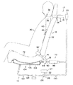
図1には本発明の第1の実施の形態に係るシートベルト装置10の構成が概略的な側面図により示されている。
<Configuration of First Embodiment>
(Configuration of shoulder side mounting assist device 12)
FIG. 1 is a schematic side view showing a configuration of a
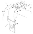
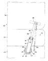
この図に示されるようにシートベルト装置10はショルダ側装着アシスト手段として装着アシスト手段の一態様を成すショルダ側装着アシスト装置12を備えている。図2及び図3に示されるように、ショルダ側装着アシスト装置12はシリンダ14を備えている。シリンダ14は筒状部16を備えている。筒状部16は軸方向がシート18の上下方向に対して交差した向き(例えば、シート18の前後方向)に沿った円筒形状に形成されている。この筒状部16の軸方向基端側には、略球形状又は、軸方向がシート18の上下方向に沿った円筒形状の軸部20が形成されている。図2に示されるように、軸部20は中空形状に形成されており、その内部は筒状部16の内部に連通している。
As shown in this figure, the
一方、上記のシート18を構成するシートバック22の後方には、支持手段としてのベース部26が設けられている。ベース部26は、シートバック22の後方でパッケージトレイトリム24上に配置されており、例えば、パッケージトレイトリム24を貫通したボルト等の締結手段によってパッケージトレイトリム24の下側の車両の骨格部材やこの骨格部材を補強する補強部材に締結固定されている。
On the other hand, a
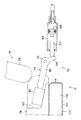
ベース部26は軸方向がシート18の上下方向に沿った円筒形状に形成されており、その内径寸法は軸部20の外径寸法よりも極僅かに大きい。また、ベース部26には窓部28が形成されており、この窓部28においてベース部26の内外が連通している。ベース部26の上下方向に沿った窓部28の開口幅は筒状部16の外径寸法よりも僅かに大きく、また、ベース部26の周方向に沿った窓部28の開口幅は筒状部16の外径寸法よりも充分に大きい。
The
ベース部26の内側にはシリンダ14の軸部20が収容されており、シリンダ14の筒状部16が窓部28を通過してベース部26の外部へ延出されている。軸部20は、ベース部26の周方向両側の窓部28の端部に筒状部16が干渉されるまでベース部26の中心軸線周りにシート18の左右方向へ揺動できる。
The
ベース部26の周方向に沿った窓部28の一端部(図2における左側の端部)に筒状部16が干渉された状態(以下、このようなシリンダ14の揺動位置を便宜上「引っ張り揺動位置」と称する)では、筒状部16はその基端部(軸部20側の端部)に対して先端部がシート18の幅方向に沿ってシート18のおける乗員30の着座位置の中央側へ傾くように窓部28が設定されている。また、ベース部26の周方向に沿った窓部28の他端部(図2における右側の端部)に筒状部16が干渉された状態(以下、このようなシリンダ14の揺動位置を便宜上「揺動初期位置」と称する)では、筒状部16はその基端部に対して先端部がシート18の幅方向に沿ってシート18のおける乗員30の着座位置の外側へ傾くように窓部28が設定されている。
A state in which the
このようにベース部26に取り付けられている筒状部16の内側には、筒状部16の軸方向に沿って摺動可能にピストン32が収容されている。筒状部16の先端側を向くピストン32の端面からは連続してウエビング支持体34のアーム36が筒状部16の先端側へ向けて延出されている。アーム36の先端側は筒状部16の先端から突出しており、その先端部にはスライドアンカ38が一体的に取り付けられている。スライドアンカ38にはアンカ孔40が形成されている。
In this manner, the
アンカ孔40はアーム36の長手方向にスライドアンカ38を貫通している。また、アンカ孔40はアーム36の長手方向及びベース部26の軸方向の双方に対して概ね直交する向きに沿って長手のスリット状に形成されており、そのアンカ孔40の長手方向寸法は、長尺帯状に形成されたウエビングベルト42の幅寸法よりも大きく、アンカ孔40をウエビングベルト42が通過している。ウエビングベルト42のアンカ孔40の通過部分よりも長手方向基端側は、パッケージトレイトリム24の裏面側やシートバック22の内部に設けられたウエビング巻取装置のスプール(図示省略)に係止されている。
The
これに対し、アンカ孔40を通過した部分よりもウエビングベルト42の先端側は、シートバック22の前面に倣ってシート18の下方へ延びており、その先端はシート18の下方で車体を構成する骨格部材やこのような骨格部材を補強するための補強部材、更には、骨格部材や補強部材と共に車体を構成する構造部材に固定されたアンカに保持されている。また、シートバック22の前面に倣ってシート18の下方へ延びたウエビングベルト42の中間部にはタング48が設けられている。シート18に着座した乗員30は、ウエビングベルト42を装着するに際してタング48を把持してタング48を引っ張ることで、ウエビングベルト42を引っ張って、ウエビングベルト42のうち上記のウエビング巻取装置のスプールに巻き取られている部分を引き出す。
On the other hand, the front end side of the
一方、図2に示されるように、軸部20の周壁には通気孔50が形成されており、通気孔50を介して軸部20の内外が連通している。但し、上記のように、軸部20はベース部26に収容されているため、軸部20の外面側の通気孔50の開口は、基本的にベース部26の周壁に閉止されている。この通気孔50に対応して、ベース部26の周壁には通気孔52が形成されており、通気孔52を介してベース部26の内外が連通している。
On the other hand, as shown in FIG. 2, a
ベース部26の軸方向に沿った通気孔52の形成位置は、通気孔50の形成位置に対応しており、図10に示されるように、引っ張り揺動位置にシリンダ14が揺動した状態では、ベース部26の中心軸線を中心とする半径方向(放射方向)に通気孔50と通気孔52とが対向し、これにより、軸部20の内側とベース部26の外側とが連通する。
The formation position of the
また、ベース部26には係止片54が形成されている。係止片54はベース部26よりもシート18の幅方向外側に設けられており、その先端側は更にシート18の幅方向外側へ延出されている。この係止片54の先端側には付勢手段としての引っ張りコイルばね56の一端が係止されている。引っ張りコイルばね56の他端部がアーム36の先端部近傍に係止されており、筒状部16の先端側へピストン32が摺動した状態では、アーム36を軸部20の側へ付勢すると共に、ベース部26の中心軸線周りシリンダ14が揺動初期位置の側へ揺動するようにアーム36を付勢する。
A locking
(バックル側装着アシスト装置72の構成)
一方、図1に示されるように、本シートベルト装置10は、バックル側装着アシスト手段として装着アシスト手段の一態様を成すバックル側装着アシスト装置72を備えている。バックル側装着アシスト装置72はアーム74を備えている。アーム74は基部76を備えている。基部76はシート18を構成するシートクッション78の後端部近傍で、シート18における乗員30の着座位置を介してショルダ側装着アシスト装置12が設けられた側やウエビングベルト42の先端部が係止されているアンカとは反対側に設けられている。
(Configuration of Buckle Side Mounting Assist Device 72)
On the other hand, as shown in FIG. 1, the
アーム74はシートクッション78の後方に設けられた車体を構成する骨格部材やこのような骨格部材を補強するための補強部材、更には、骨格部材や補強部材と共に車体を構成する構造部材にシート18の幅方向を軸方向とする軸周りに回動自在に支持されている。基部76の外周部からは、概ね、シート18の前方側へ向けてバックル支持片80が延出されている。バックル支持片80の先端部にはバックル82が固定されている。
The
上記のように、シート18に着座した乗員30は、タング48を引っ張ることで、ウエビングベルト42を引っ張って身体の前方にウエビングベルト42を掛け回してからタング48をバックル82に装着すると、タング48よりもウエビングベルト42の長手方向基端側は乗員30の肩部から胸部を介して腰部近傍までを拘束するショルダベルトとなり、タング48よりもウエビングベルト42の先端側は乗員30の腰部を拘束するラップベルトになる。
As described above, when the
また、基部76におけるアーム74の回動中心周りにシリンダ86から所定角度離間した位置では、基部76の外周部から被押圧片84が延出されており、シート18の前後方向に沿った被押圧片84の後ろ側から被押圧片84が押圧されると、基部76における回動中心周りにアーム74が回動して、バックル支持片80の先端に固定されたバックル82が上昇するように基部76における回動中心周りに回動する。
Further, at a position spaced apart from the
以上の構成のアーム74は、基部76における回動中心周りにバックル82が上昇するような回動方向とは反対方向(すなわち、図1における左周り方向)に捩じりコイルばね等の付勢部材により付勢されており、このため、被押圧片84の後ろ側からの押圧力が被押圧片84に付与されていない状態では、図1及び図4に示されるように、シートクッション78の座面(上面)よりもバックル82が下側、例えば、シートクッション78に形成されたポケット83内に位置している。
The
一方、被押圧片84の後方にはシリンダ86が設けられている。シリンダ86は軸方向が概ねシート18の前後方向に沿った筒形状に形成されており、図4に示されるように、その内部にはピストン88がシリンダ86の軸方向に沿って摺動可能に収容されている。シート18の前方側を向くピストン88の端部からはロッド90がシリンダ86の軸方向先端側へ向けて延出されている。ロッド90の先端側はシリンダ86の先端部からシリンダ86の外部へ突出しており、更に、ロッド90の先端部は被押圧片84と対向している。このため、ピストン88がシリンダ86の先端側へ摺動すると、ロッド90の先端部が被押圧片84をシート18の前方側へ押圧し、これにより、アーム74が回動する。
On the other hand, a
(アシストガス供給装置102の構成)
一方、図1に示されるように、シートベルト装置10はショルダ側装着アシスト装置12やバックル側装着アシスト装置72と共に装着アシスト手段を構成するアシストガス供給装置102を備えている。アシストガス供給装置102は袋体104を備えている。袋体104はシートクッション78を構成するクッション材の下側に設けられている。
(Configuration of assist gas supply device 102)
On the other hand, as shown in FIG. 1, the
アシストガス供給装置102の内部には弾性体としてのクッション材106が設けられている。クッション材106は上記のシートクッション78を構成するクッション材よりも柔らかい材料により形成されている。クッション材106はその弾性により袋体104を膨張させている。しかしながら、クッション材106の弾性に抗する荷重が袋体104に荷重が作用すると、クッション材106は圧縮されるように弾性変形し、更に、袋体104が萎む。また、このような荷重が解消されると、クッション材106は弾性により復元すると共に、クッション材106の復元により袋体104が再度膨張する。
A
(流路機構122の構成)
さらに、図1に示されるように、シートベルト装置10は流路機構122を備えており、この流路機構122によって上記のショルダ側装着アシスト装置12、バックル側装着アシスト装置72、及びアシストガス供給装置102が繋がっている。
(Configuration of flow path mechanism 122)
Further, as shown in FIG. 1, the
詳細には、流路機構122は第1接続手段を構成するチューブ124を備えている。チューブ124の一端は袋体104に接続されており、袋体104の内部に連通している。このため、上記のように、袋体104に荷重が作用して袋体104が萎むと、特許請求の範囲で言う「流体」の一態様である袋体104内の空気はチューブ124に送り込まれる。これに対し、チューブ124の他端は三方弁126の筐体128に繋がっており、この筐体128の内部に連通している。
Specifically, the
一方、流路機構122はチューブ124と共に第1接続手段を構成するチューブ130を備えている。チューブ130の一端は筐体128に繋がっており、筐体128の内部に連通している。チューブ130は他端側における中間部で二股に分かれており、チューブ130の一方の他端はベース部26を貫通して軸部20に繋がり、軸部20の内部に連通している。
On the other hand, the
これに対し、チューブ130の他方の他端はシリンダ86に繋がり、シリンダ86の内部に連通している。このため、袋体104に荷重が作用して萎むことで、袋体104からチューブ124へ空気が放出されると、チューブ130内の空気の一部が軸部20に供給されて軸部20の内圧を上昇させ、チューブ130内の空気の他の一部がシリンダ86に供給されてシリンダ86の内圧を上昇させる。
On the other hand, the other end of the
一方、流路機構122は第2接続手段としてのチューブ132を備えている。チューブ132の一端は筐体128に接続されており、筐体128の内部に連通している。チューブ132の他端は流体供給手段としてのインフレータ134に接続されており、インフレータ134の内部に連通している。インフレータ134の内部には、燃焼することで瞬時に特許請求の範囲で言う流体の一態様であるガスを発生させるガス発生剤や、このガス発生剤を燃焼させる着火剤、更には、この着火剤を着火する着火装置が収容されている。
On the other hand, the
着火装置は図示しない制御手段としてのECUに接続されており、シート18を構成するシートクッション78や、シートバック22に設けられた圧力センサ等の荷重検出手段が、シート18への乗員30の着座を検出した状態で、車両に搭載された加速度センサ等の車両急減速状態検出手段が、車両の急減速状態を検出すると、ECUが着火装置を作動させる。着火装置が作動して着火剤が着火されると、ガス発生剤が燃焼されてガスが発生する。このようにして発生されたガスは、チューブ132に送り込まれて、更に、筐体128の内部に送りこまれる。
The ignition device is connected to an ECU (not shown) as control means, and a
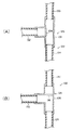
図5に示されるように、筐体128の内部には弁体136が設けられている。弁体136は図5の(A)に示されるように、流路機構122とチューブ130との間を開放してチューブ132の側を閉塞するように図示しない捩じりコイルばね等の弁体付勢手段によって付勢されている。
As shown in FIG. 5, a
しかしながら、上記のように、インフレータ134にて発生したガスがチューブ132に送り込まれると、このガスの圧力により弁体付勢手段の付勢力に抗して弁体136が筐体128内で回動する。図5の(B)に示されるように、このように回動した弁体136は、チューブ130とチューブ124との間を閉止して、チューブ132とチューブ124との間を開放する。これにより、インフレータ134にて発生したガスがチューブ124を通過して袋体104に供給される。
However, as described above, when the gas generated in the
<第1の実施の形態の作用、効果>
図1に示される乗員30がシート18に着座していない状態では、図2及び図3に示されるように、アーム36がシリンダ14に収容されて、スライドアンカ38はシートバック22の上側に位置しているため、スライドアンカ38よりも先端側では、ウエビングベルト42がシートバック22の前面の近傍でシートバック22に倣って下方へ延びている。
<Operation and Effect of First Embodiment>
In the state where the
しかも、筒状部16は揺動初期位置にあり、引っ張りコイルばね56の付勢力でベース部26の周方向に沿った窓部28の他端部(図2における右側の端部)に筒状部16が干渉されるまでシリンダ14が揺動しており、このため、筒状部16はその基端部に対して先端部がシート18の幅方向に沿ってシート18のおける乗員30の着座位置の外側へ傾いている。このため、乗員30がシート18に着座するに際してウエビング支持体34やウエビングベルト42が乗員30の身体に干渉し辛い。このため、乗員30はシート18に円滑に着座できる。
Moreover, the
また、この状態では、図4に示されるように、バックル82はポケット83内等、シートクッション78の座面(上面)よりも下方に位置しているので、シート18に乗員30が着座するに際して乗員30の身体にバックル82が干渉し辛い。したがっても、これによっても乗員30はシート18に円滑に着座できる。
In this state, as shown in FIG. 4, the
一方、図6に示されるように、乗員30がシート18に着座すると、乗員30の体重がシートクッション78に作用する。クッション材106はシートクッション78のクッション材よりも柔らかいので、シートクッション78のクッション材が乗員30の体重で圧縮されるよりも先に袋体104が乗員30の体重で萎みながら、クッション材106が圧縮される。
On the other hand, as shown in FIG. 6, when the
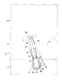
このように袋体104が萎む際には、袋体104内の空気がチューブ124に放出される。図5の(A)に示されるように、通常は筐体128内の弁体136が流路機構122とチューブ130との間を開放してチューブ132の側を閉塞しているため、チューブ124に袋体104内の空気が放出されると、チューブ130の内圧が上昇し、更に、チューブ130の一方の他端に繋がっているシリンダ14の内圧が上昇する。シリンダ14の内圧が上昇すると、筒状部16の先端側へピストン32が摺動し、これにより、図7及び図8に示されるように、ウエビング支持体34がシートバック22の前方側へ移動する。
Thus, when the
これにより、スライドアンカ38でのウエビングベルト42の折り返し位置がシートバック22の前方側に移動するので、シートバック22の前面に倣うように下方へ延びているウエビングベルト42は、少なくともスライドアンカ38の近傍でシートバック22の前面よりも前側に離間する。このように、ウエビングベルト42がシートバック22の前面よりも前側に離間することで、シート18に着座した乗員30はウエビングベルト42に設けられたタング48を把持しやすくなる。これにより、乗員30は簡単にタング48を把持して、ウエビングベルト42を装着するためにタング48を引っ張ることができる。
As a result, the folding position of the
一方、上記のように、チューブ124に袋体104内の空気が放出されることでチューブ130の内圧が上昇すると、チューブ130の他方の他端に繋がっているシリンダ86の内圧が上昇する。シリンダ86の内圧が上昇すると、シリンダ86の先端側へピストン88が摺動し、これにより、図9に示されるように、ロッド90が前方へ移動して、被押圧片84を後方から押圧する。このように被押圧片84が後方から押圧されることで、基部76におけるアーム74の回動中心周りにアーム74が回動すると、バックル支持片80の先端が上昇するように回動し、これにより、バックル82が上昇するように回動する。
On the other hand, as described above, when the internal pressure of the
このようにして、バックル82が上昇することで、シートクッション78の座面(上面)よりも上側にバックル82が位置するので、乗員30はバックル82を確認しやすく、しかも、上記のように引っ張ったタング48をバックル82に簡単に装着できる。
As the
また、上記のように、ウエビングベルト42を身体に掛け回すためにバックル82の側へタング48を引っ張ると、アンカ孔40を通過しているウエビングベルト42がスライドアンカ38、ひいては、ウエビング支持体34をシート18における乗員30の着座位置の幅方向中央側へ引っ張る。このようにウエビング支持体34が引っ張られることで、図10に示されるように、シリンダ14はベース部26の中心軸線を中心に引っ張り揺動位置まで揺動する。これにより、スライドアンカ38が乗員30の肩部に接近するので、ウエビングベルト42を乗員30の身体に適した状態で装着できる。
Further, as described above, when the
さらに、このようにシリンダ14が引っ張り揺動位置まで揺動すると、図10に示されるように、軸部20の通気孔50とベース部26の通気孔52とが連通し、軸部20の内部とベース部26の外部とが連通する。この状態では、軸部20内の空気は通気孔50、52を介してベース部26の外部へ抜け出ることができるので、軸部20の内圧が引っ張りコイルばね56の付勢力に抗することができない。したがって、この状態では、引っ張りコイルばね56の付勢力でウエビング支持体34がシリンダ14の内側に引き込まれる。これにより、スライドアンカ38がシートバック22の上側に戻るので、スライドアンカ38が乗員30の身体(例えば、肩部)に干渉することがない。
Further, when the
このように、本シートベルト装置10では、乗員30がシート18に着座した際の荷重で袋体104から放出された空気によって、ウエビング支持体34やバックル82を移動させ、簡単にタング48を把持してバックル82にタング48を装着できる。しかも、このようにウエビング支持体34やバックル82を移動させるに際してモータを用いないので、複雑な制御が不要である。
As described above, in the
これにより、コストを安価にできる。さらに、このようにモータを用いないので、乗員30がシート18に着座したことを検出するセンサも不要であるので、この意味でも複雑な制御が不要でコストを安価にできる。さらに、乗員30がシート18から離れることで、袋体104に乗員30の体重が作用しなくなれば、クッション材106がその弾性で復元し、袋体104を再度膨張させるので、袋体104を復元させるための特別な流体供給源も不要である。このため、更にコストを安価にできる。
Thereby, the cost can be reduced. Further, since the motor is not used in this way, a sensor for detecting that the
さらに、乗員30がシート18に着座した際の荷重で袋体104は萎むものの、特に大きな引っ張り荷重が袋体104に作用することはない。また、萎んだ袋体104はクッション材106によって膨張させられるが、この際にも特に大きな引っ張り荷重が袋体104に作用することはない。このため、袋体104に特に高い強度を付与しなくても、充分な耐久性を有しているので、長期に亘り良好な動作性を安価に確保できる。
Furthermore, although the
一方、車両急減速状態になったことを車両に搭載された加速度センサ等の車両急減速状態検出手段が検出すると、ECUがインフレータ134内の着火装置を作動させる。着火装置が作動して着火剤が着火されると、ガス発生剤が燃焼されてガスが発生する。このようにしてインフレータ134で発生したガスは、チューブ132に送り込まれて、更に、筐体128の内部に送りこまれる。
On the other hand, when the vehicle sudden deceleration state detecting means such as an acceleration sensor mounted on the vehicle detects that the vehicle is suddenly decelerated, the ECU activates the ignition device in the
インフレータ134内で発生したガスが筐体128に送り込まれると、弁体136はこのガスの圧力で弁体付勢手段の付勢力に抗して回動する。これにより、図5の(B)に示されるように、弁体136がチューブ130とチューブ124との間を閉止して、チューブ132とチューブ124との間を開放すると、インフレータ134にて発生したガスは袋体104に送り込まれて袋体104を強制的に膨張させる。これにより、図12に示されるように、シートクッション78の座面が上昇すると、シート18での乗員30の着座姿勢が変化し、所謂「サブマリン現象」の発生を防止又は防止する等、ウエビングベルト42による乗員30の身体の拘束性が向上する。
When the gas generated in the
しかも、上記特許文献1に開示された乗員拘束装置とは異なり、インフレータ134にて発生したガスの圧力で膨張して乗員30の着座姿勢を変化させる袋体104を、車両急減速時のみならず、通常時にウエビング支持体34やバックル82を移動させるためのガス圧の供給源として有効に利用できる。
Moreover, unlike the occupant restraint device disclosed in Patent Document 1, the
また、本実施の形態では、上記のように、袋体104はインフレータ134から供給されたガスの圧力に耐え得る強度を有しているので、乗員30がシート18に着座した際の荷重やクッション材106によって膨張させられる際の荷重にのみ耐えられるような強度よりも充分に高い強度を有することになる。したがって、この意味でも袋体104に特に高い強度を付与しなくても、充分な耐久性を有しているので、長期に亘り良好な動作性を安価に確保できる。しかも、乗員30がシート18に着座することで萎んだ袋体104を復元させる構成が、シートクッション78を構成するクッション材よりも柔らかい材料により形成されたクッション材106であるので、乗員30がシート18に着座した際の座り心地が悪くなることはない。
In the present embodiment, as described above, since the
なお、本実施の形態では、ショルダ側装着アシスト装置12とシートクッション78の双方を備える構成であるが、ショルダ側装着アシスト装置12又はシートクッション78を備えない構成としてもよい。
In addition, in this Embodiment, although it is the structure provided with both the shoulder side mounting
また、本実施の形態は、インフレータ134を備える構成であったが、インフレータ134を備えない構成としてもよい。
Moreover, although this Embodiment was the structure provided with the
さらに、本実施の形態では、アシストガス供給装置102をシートクッション78のクッション材の下側に設けた構成であったが、アシストガス供給装置102をシートバック22のクッション材の後ろ側に設けて、乗員30がシートバック22に凭れ掛かった際の荷重でショルダ側装着アシスト装置12やバックル側装着アシスト装置72を作動させる構成としてもよい。
Further, in the present embodiment, the assist
また、本実施の形態では、袋体104から放出される空気、及び、インフレータ134から放出されるガスを特許請求の範囲で言うところの「流体」の一態様としたが、流体がこのような空気やガスに限定されるものではなく、液体等の他の流体を利用してもよい。
In the present embodiment, the air discharged from the
<第2の実施の形態の構成>
次に、本発明の第2の実施の形態について説明する。なお、本実施の形態を説明するにあたり、前記第1の実施の形態と基本的に同一の部位に関しては同一の符号を付与してその詳細な説明を省略する。また、本実施の形態は、上記のバックル側装着アシスト装置72の変形例であるので、ショルダ側装着アシスト装置12やアシストガス供給装置102、流路機構122等に関しては基本的に変更がないものとしてその詳細な説明は省略する。
<Configuration of Second Embodiment>
Next, a second embodiment of the present invention will be described. In the description of the present embodiment, the same reference numerals are assigned to the same parts as those in the first embodiment, and the detailed description thereof is omitted. Further, since the present embodiment is a modification of the buckle side mounting assist
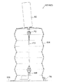
図13には、本実施の形態に係るシートベルト装置160においてショルダ側装着アシスト手段として装着アシスト手段の一態様を成すバックル側装着アシスト装置162の構成の概略が側面断面図によって示されている。この図に示されるように、バックル側装着アシスト装置162は蛇腹筒164を備えている。蛇腹筒164は上下方向に伸縮可能に形成されており、その下端はシート18のシートクッション78の下側で車体を構成する構造部材166に固定された状態で閉止されている。蛇腹筒164の内側にはアンカプレート168が設けられている。アンカプレート168は上記の構造部材166に固定されている。また、アンカプレート168には連結部材170の一端が係止されている。連結部材170は上記のウエビングベルト42やワイヤ等の可撓性を有する部材により形成されている。
FIG. 13 is a side sectional view schematically showing a configuration of a buckle side mounting
一方、蛇腹筒164の上端部の上側にはバックル82が設けられており、バックル82のタング48が挿入される側とは反対側から延出された固定プレート172が蛇腹筒164の上端を貫通して蛇腹筒164の内側に入り込んでいる。このように、蛇腹筒164の内側に入り込んだ固定プレート172には、上記の連結部材170の他端が係止されている。ここで、連結部材170の長さは、蛇腹筒164が上端部と下端部とが最も離間して蛇腹筒164が伸びた状態でのアンカプレート168での連結部材170の係止位置と、固定プレート172での連結部材170の係止位置との間隔との間隔と同じかそれ以上に設定されている。
On the other hand, a
また、蛇腹筒164の下端部近傍には接続部174が形成されており、チューブ130の他方の他端部が接続される。
Further, a
<第2の実施の形態の作用、効果>
以上の構成の本実施の形態では、乗員30がシート18に着座する前の状態では、蛇腹筒164が縮んだ状態になっており、この状態では、バックル82がポケット83内等、シートクッション78の座面(上面)よりも下方に位置しているので、シート18に乗員30が着座するに際して乗員30の身体にバックル82が干渉し辛い。したがっても、これによっても乗員30はシート18に円滑に着座できる。
<Operation and Effect of Second Embodiment>
In the present embodiment having the above-described configuration, the
一方、乗員30がシート18に着座することで袋体104が萎んで袋体104内の空気がチューブ124に放出されると、チューブ130の内圧が上昇し、チューブ130の他方の他端に繋がっている蛇腹筒164の内圧が上昇する。蛇腹筒164の内圧が上昇すると、図14に示されるように、蛇腹筒164の下端部から蛇腹筒164の上端部が離間するように蛇腹筒164が伸び、これにより、バックル82が持ち上げられて上昇する。
On the other hand, when the
これにより、シートクッション78の座面(上面)よりも上側にバックル82が位置するので、乗員30はバックル82を確認しやすく、しかも、上記のように引っ張ったタング48をバックル82に簡単に装着できる。このように、本実施の形態でも、前記第1の実施の形態と同様の効果を得ることができる。
As a result, the
10 シートベルト装置
14 シリンダ
18 シート
22 シートバック
26 ベース部(支持手段)
34 ウエビング支持体
42 ウエビングベルト
48 タング
104 袋体
106 クッション材(付勢手段)
124 チューブ(第1接続手段)
126 三方弁(弁)
130 チューブ(第1接続手段)
132 チューブ(第2接続手段)
160 シートベルト装置
DESCRIPTION OF
34
124 Tube (first connecting means)
126 Three-way valve (valve)
130 Tube (first connecting means)
132 Tube (second connection means)
160 Seat belt device
Claims (5)
前記着座位置の側方で且つ前記シートバックの上側の初期位置に設けられて、前記初期位置を通過する前記ウエビングベルトを支持するウエビング支持体と、
前記着座位置の側方の初期位置に設けられて、前記乗員の身体に前記ウエビングベルトが装着される際には前記ウエビングベルトに設けられたタングが装着されるバックルと、
前記シートに設けられて前記シートに着座した前記乗員からの荷重で萎んで内部の流体を放出し、この放出した流体の圧力で前記ウエビング支持体及びバックルの少なくとも何れかの一方を、その初期位置に対して所定の向きに離間した装着アシスト位置へ移動させる袋体と、
前記袋体の内部に設けられ、前記荷重を受けることで圧縮されると共に前記荷重が解消されることで弾性により復元し、復元することで萎んだ前記袋体を膨らませて前記袋体に流体を吸入させる弾性体と、
を備えるシートベルト装置。 A long length provided behind or below the seat back constituting the seat and capable of restraining the occupant's body by being attached to the occupant's body seated on the seat from the side of the seating position of the occupant in the seat A belt webbing belt;
A webbing support provided at an initial position on the side of the seating position and on the upper side of the seat back to support the webbing belt passing through the initial position;
A buckle that is provided at an initial position on the side of the seating position and on which a tongue provided on the webbing belt is worn when the webbing belt is worn on the body of the occupant;
It is deflated by a load from the occupant seated on the seat and is released from the internal fluid, and at least one of the webbing support and the buckle is moved to its initial position by the pressure of the released fluid. A bag body that is moved to a mounting assist position separated in a predetermined direction with respect to
It is provided inside the bag body, is compressed by receiving the load and is restored by elasticity when the load is eliminated, and the bag body that has been deflated by inflating is inflated to supply fluid to the bag body. An elastic body to be inhaled;
A seat belt device comprising:
前記第1接続手段の中間部と前記流体供給手段とを繋ぎ、前記流体供給手段からの流体が通過する管状の第2接続手段と、
前記第1接続手段と前記第2接続手段との接続部分に設けられ、通常は前記第1接続手段と前記第2接続手段との間を閉止して前記第1接続手段を開放すると共に、前記車両急減速状態では前記第1接続手段と前記第2接続手段との接続部分と前記ウエビング支持体及び前記バックルのうち前記袋体から放出された流体の圧力で移動する方との間を閉止して前記第1接続手段と前記第2接続手段との接続部分と前記袋体との間を開放する弁と、
を備える請求項1又は請求項2に記載のシートベルト装置。 A tubular first connection means for connecting the bag body and the one that moves with the pressure of the fluid discharged from the bag body of the webbing support body and the buckle, and through which the fluid discharged from the bag body passes;
A tubular second connecting means for connecting the intermediate portion of the first connecting means and the fluid supply means, and through which the fluid from the fluid supply means passes;
Provided at a connection portion between the first connection means and the second connection means, and normally closes the space between the first connection means and the second connection means to open the first connection means, and In the vehicle sudden deceleration state, the connection portion between the first connection means and the second connection means is closed between the webbing support body and the buckle that moves with the pressure of the fluid discharged from the bag body. A valve that opens between the bag and the connecting portion between the first connecting means and the second connecting means,
The seatbelt apparatus of Claim 1 or Claim 2 provided with this.
前記ウエビング支持体の初期位置に対応して前記シートバックの上端部又は当該上端部の近傍に設けられ、前記シリンダの先端が底部よりも前記シートの前方を向いた状態で、前記シリンダを前記シートの上下方向を軸方向とする軸周りに揺動可能に支持し、更に、前記通気部を閉止すると共に、前記乗員が前記ウエビングベルトを装着するにあたり前記ウエビングベルト及び前記ウエビング支持体を介して前記シリンダを引っ張り、前記シートの上下方向を軸方向とする軸周りに前記シリンダを揺動させることで前記通気部を開放する支持部材と、
前記ウエビング支持体を前記シリンダの底部側へ付勢すると共に、前記乗員が前記ウエビングベルトを装着するにあたり前記ウエビングベルト及び前記ウエビング支持体を介して前記シリンダを引っ張った際の前記シリンダの揺動方向とは反対向きに前記ウエビング支持体を付勢する付勢手段と、
を備える請求項1から請求項4の何れか1項に記載のシートベルト装置。 The webbing support is accommodated so as to be slidable to the tip side and the opposite bottom side, and the internal pressure rises by supplying the fluid from the bottom side. A cylinder in which a webbing support is slid to the tip side, and a ventilation part is formed on the bottom side of the webbing support to communicate inside and outside;
Corresponding to the initial position of the webbing support, the seat back is provided at or near the upper end of the seat back, and the cylinder is placed in the seat with the front end of the cylinder facing the front of the seat rather than the bottom. Is supported so as to be swingable around an axis having an up-and-down direction as an axial direction, and further, the ventilation portion is closed, and the occupant wears the webbing belt through the webbing belt and the webbing support. A support member that opens the ventilation part by pulling the cylinder and swinging the cylinder about an axis whose axial direction is the vertical direction of the seat;
The urging direction of the cylinder when the occupant pulls the cylinder via the webbing belt and the webbing support when the occupant attaches the webbing belt while urging the webbing support to the bottom side of the cylinder Biasing means for biasing the webbing support in the opposite direction;
The seat belt device according to any one of claims 1 to 4, further comprising:
Priority Applications (1)
| Application Number | Priority Date | Filing Date | Title |
|---|---|---|---|
| JP2009005858A JP5226543B2 (en) | 2009-01-14 | 2009-01-14 | Seat belt device |
Applications Claiming Priority (1)
| Application Number | Priority Date | Filing Date | Title |
|---|---|---|---|
| JP2009005858A JP5226543B2 (en) | 2009-01-14 | 2009-01-14 | Seat belt device |
Publications (2)
| Publication Number | Publication Date |
|---|---|
| JP2010162995A true JP2010162995A (en) | 2010-07-29 |
| JP5226543B2 JP5226543B2 (en) | 2013-07-03 |
Family
ID=42579528
Family Applications (1)
| Application Number | Title | Priority Date | Filing Date |
|---|---|---|---|
| JP2009005858A Expired - Fee Related JP5226543B2 (en) | 2009-01-14 | 2009-01-14 | Seat belt device |
Country Status (1)
| Country | Link |
|---|---|
| JP (1) | JP5226543B2 (en) |
Cited By (1)
| Publication number | Priority date | Publication date | Assignee | Title |
|---|---|---|---|---|
| JP2016030496A (en) * | 2014-07-28 | 2016-03-07 | 株式会社東海理化電機製作所 | Seat belt device |
Citations (3)
| Publication number | Priority date | Publication date | Assignee | Title |
|---|---|---|---|---|
| JPS6332053U (en) * | 1986-08-19 | 1988-03-01 | ||
| JP2004017686A (en) * | 2002-06-12 | 2004-01-22 | Takata Corp | Occupant protection device |
| JP2004299657A (en) * | 2003-04-01 | 2004-10-28 | Araco Corp | Vehicle seat |
-
2009
- 2009-01-14 JP JP2009005858A patent/JP5226543B2/en not_active Expired - Fee Related
Patent Citations (3)
| Publication number | Priority date | Publication date | Assignee | Title |
|---|---|---|---|---|
| JPS6332053U (en) * | 1986-08-19 | 1988-03-01 | ||
| JP2004017686A (en) * | 2002-06-12 | 2004-01-22 | Takata Corp | Occupant protection device |
| JP2004299657A (en) * | 2003-04-01 | 2004-10-28 | Araco Corp | Vehicle seat |
Cited By (1)
| Publication number | Priority date | Publication date | Assignee | Title |
|---|---|---|---|---|
| JP2016030496A (en) * | 2014-07-28 | 2016-03-07 | 株式会社東海理化電機製作所 | Seat belt device |
Also Published As
| Publication number | Publication date |
|---|---|
| JP5226543B2 (en) | 2013-07-03 |
Similar Documents
| Publication | Publication Date | Title |
|---|---|---|
| JP6269619B2 (en) | Vehicle seat belt device and occupant protection device | |
| JP2007125972A (en) | Occupant restraining system | |
| JP2002264700A (en) | Seat rail device with position detection mechanism | |
| JP2007137181A (en) | Air belt device | |
| JP2023161946A (en) | Seat-mounted airbag device | |
| JP6401625B2 (en) | Airbag device | |
| JP5952680B2 (en) | Airbag device | |
| JP2009154745A (en) | Vehicle seat belt device | |
| JP5226543B2 (en) | Seat belt device | |
| JP3907895B2 (en) | Airbag system | |
| JPH11268608A (en) | Air belt device | |
| JP2001213256A (en) | Air belt | |
| JP2009184646A (en) | Side airbag device | |
| JP4581942B2 (en) | Crew restraint system | |
| JP4631776B2 (en) | Airbag device for passenger seat | |
| JP2007106355A (en) | Seat belt device | |
| JP2023183143A (en) | Occupant protection device | |
| JP3922259B2 (en) | Vehicle headrest device | |
| JP2011140269A (en) | Side airbag device and vehicle seat | |
| JP2010052622A (en) | Occupant crash protector | |
| JPH092190A (en) | Vehicle airbag device | |
| JP7380624B2 (en) | Occupant protection device | |
| JP4428334B2 (en) | Crew restraint system | |
| JP2007022437A (en) | Crew restraint system | |
| JP2011168134A (en) | Occupant protection device |
Legal Events
| Date | Code | Title | Description |
|---|---|---|---|
| A621 | Written request for application examination |
Free format text: JAPANESE INTERMEDIATE CODE: A621 Effective date: 20110808 |
|
| A977 | Report on retrieval |
Free format text: JAPANESE INTERMEDIATE CODE: A971007 Effective date: 20121122 |
|
| A131 | Notification of reasons for refusal |
Free format text: JAPANESE INTERMEDIATE CODE: A131 Effective date: 20121204 |
|
| A521 | Written amendment |
Free format text: JAPANESE INTERMEDIATE CODE: A523 Effective date: 20130204 |
|
| TRDD | Decision of grant or rejection written | ||
| A01 | Written decision to grant a patent or to grant a registration (utility model) |
Free format text: JAPANESE INTERMEDIATE CODE: A01 Effective date: 20130312 |
|
| A61 | First payment of annual fees (during grant procedure) |
Free format text: JAPANESE INTERMEDIATE CODE: A61 Effective date: 20130314 |
|
| R150 | Certificate of patent or registration of utility model |
Ref document number: 5226543 Country of ref document: JP Free format text: JAPANESE INTERMEDIATE CODE: R150 Free format text: JAPANESE INTERMEDIATE CODE: R150 |
|
| FPAY | Renewal fee payment (event date is renewal date of database) |
Free format text: PAYMENT UNTIL: 20160322 Year of fee payment: 3 |
|
| LAPS | Cancellation because of no payment of annual fees |