JP2010200436A - Driving device - Google Patents
Driving device Download PDFInfo
- Publication number
- JP2010200436A JP2010200436A JP2009040707A JP2009040707A JP2010200436A JP 2010200436 A JP2010200436 A JP 2010200436A JP 2009040707 A JP2009040707 A JP 2009040707A JP 2009040707 A JP2009040707 A JP 2009040707A JP 2010200436 A JP2010200436 A JP 2010200436A
- Authority
- JP
- Japan
- Prior art keywords
- pair
- piezoelectric element
- pressing
- pressing bodies
- drive device
- Prior art date
- Legal status (The legal status is an assumption and is not a legal conclusion. Google has not performed a legal analysis and makes no representation as to the accuracy of the status listed.)
- Granted
Links
- 230000008602 contraction Effects 0.000 claims abstract description 10
- 230000036316 preload Effects 0.000 claims description 25
- CNQCVBJFEGMYDW-UHFFFAOYSA-N lawrencium atom Chemical compound [Lr] CNQCVBJFEGMYDW-UHFFFAOYSA-N 0.000 abstract description 30
- 238000005452 bending Methods 0.000 abstract description 10
- 230000003247 decreasing effect Effects 0.000 description 3
- 230000005484 gravity Effects 0.000 description 1
- 230000001939 inductive effect Effects 0.000 description 1
- 230000010287 polarization Effects 0.000 description 1
Images


Landscapes
- General Electrical Machinery Utilizing Piezoelectricity, Electrostriction Or Magnetostriction (AREA)
Abstract
Description
本発明は、スムーズインパクト駆動機構を用いた駆動装置に関する。 The present invention relates to a drive device using a smooth impact drive mechanism.
近年、スムーズインパクト駆動機構を用いた駆動装置が開発されている。スムーズインパクト駆動機構は、移動体の慣性と摩擦力とを利用しつつ、圧電素子の伸縮の一方を緩やかに駆動し、他方を急峻に駆動することで移動体を繰り出すものである。このような駆動機構を利用した位置決め装置等が提案されている(たとえば、特許文献1および特許文献2参照)。 In recent years, drive devices using a smooth impact drive mechanism have been developed. The smooth impact driving mechanism is a mechanism that drives the moving body by gently driving one of the expansion and contraction of the piezoelectric element and abruptly driving the other while utilizing the inertia and frictional force of the moving body. A positioning device using such a drive mechanism has been proposed (see, for example, Patent Document 1 and Patent Document 2).
特許文献1記載の位置決め装置は、移動体と衝撃力発生機構を用いて目標物体を位置決めする。この装置では、移動体が衝撃間隙を介して目標物体に対向する衝撃面を備えている。また、衝撃力発生機構が移動体に一端を固定した圧電素子と圧電素子の他端に設けられた慣性体とから構成されている。このようにして正確な微小移動を行っている。 The positioning device described in Patent Document 1 positions a target object using a moving body and an impact force generation mechanism. In this apparatus, the moving body includes an impact surface that faces the target object via an impact gap. Further, the impact force generation mechanism is composed of a piezoelectric element having one end fixed to the moving body and an inertial body provided at the other end of the piezoelectric element. In this way, accurate minute movement is performed.
特許文献2記載の駆動装置は、容量性負荷に直列に接続され、容量性負荷とともに直列共振回路を構成する誘導性素子および抵抗素子と、直列共振回路に矩形波形の電圧を印加する電圧印加手段とを備える。その結果、簡単な構成で容量性負荷に鋸波形の電圧を印加できるようにしている。 The driving device described in Patent Document 2 is connected in series to a capacitive load, and an inductive element and a resistance element that form a series resonance circuit together with the capacitive load, and a voltage applying unit that applies a rectangular waveform voltage to the series resonance circuit With. As a result, a sawtooth waveform voltage can be applied to the capacitive load with a simple configuration.
しかしながら、上記の特許文献に記載されている装置では、移動体側の重力等で予圧をかけて摩擦力を調整しスムーズインパクト駆動を可能にしており、予圧調整が困難である。また、従来の装置では、予圧の方向が偏っており、圧電素子が伸縮する際に曲げや引っ張りの応力が生じ圧電素子の損傷を招きかねない。本発明は、このような事情に鑑みてなされたものであり、被駆動体側の状況に応じた予圧調整が容易で、圧電素子に曲げ応力等の負担がかからない駆動装置を提供することを目的とする。 However, in the apparatus described in the above-mentioned patent document, it is difficult to adjust the preload because the preload is applied by gravity or the like on the moving body to adjust the frictional force and enable the smooth impact drive. Further, in the conventional apparatus, the direction of the preload is biased, and when the piezoelectric element expands and contracts, bending or tensile stress is generated, which may cause damage to the piezoelectric element. The present invention has been made in view of such circumstances, and it is an object of the present invention to provide a driving device in which preload adjustment according to the situation on the driven body side is easy and the piezoelectric element is not burdened with bending stress or the like. To do.
(1)上記の目的を達成するため、本発明の駆動装置は、スムーズインパクト駆動機構を有する駆動装置であって、一端を固定され、電圧の印加により伸縮する圧電素子と、前記圧電素子の他端に設けられ、前記圧電素子の伸縮方向に垂直でそれぞれ逆向きに押圧力を有する一対の押圧体と、前記一対の押圧体に押圧される一対の壁部を有する被駆動体と、を備え、前記圧電素子の伸縮により、前記一対の押圧体が前記被駆動体をスムーズインパクト駆動することを特徴としている。 (1) In order to achieve the above object, a drive device according to the present invention is a drive device having a smooth impact drive mechanism, which is fixed at one end and expands and contracts by application of a voltage; A pair of pressing bodies provided at the ends and having a pressing force perpendicular to the expansion and contraction direction of the piezoelectric element and opposite to each other; and a driven body having a pair of wall portions pressed by the pair of pressing bodies. The pair of pressing bodies smoothly drives the driven body by the expansion and contraction of the piezoelectric element.
このように本発明の駆動装置は、圧電素子の伸縮の際に駆動側からの押圧力に基づく摩擦を利用して被駆動体を駆動する。これにより、移動体側の状況に応じて調整がし易くなる。そして、複雑な予圧機構も必要なくなる。また、圧電素子の伸縮方向に垂直で対称な方向に押圧力がかかるため、予圧の方向にバランスが取れており、圧電素子に曲げなどの応力がかかりにくい。したがって、圧電素子への負担が軽減される。 Thus, the drive device of the present invention drives the driven body using friction based on the pressing force from the drive side when the piezoelectric element expands and contracts. Thereby, it becomes easy to adjust according to the situation by the side of a moving body. Further, a complicated preload mechanism is not necessary. In addition, since a pressing force is applied in a direction that is perpendicular to and symmetrical with respect to the expansion / contraction direction of the piezoelectric element, the preload direction is balanced and stress such as bending is not easily applied to the piezoelectric element. Therefore, the burden on the piezoelectric element is reduced.
(2)また、本発明の駆動装置は、前記一対の押圧体が、互いに対称な力で押圧することを特徴としている。これにより、圧電素子に曲げ応力がかからず、圧電素子にかかる負担を低減できる。 (2) Moreover, the drive device of the present invention is characterized in that the pair of pressing bodies press with a force symmetrical to each other. Thereby, a bending stress is not applied to the piezoelectric element, and the burden on the piezoelectric element can be reduced.
(3)また、本発明の駆動装置は、前記一対の押圧体が、板バネであることを特徴としている。これにより、駆動部分の先端を軽量化することができる。また、予圧の強さを容易に調整することができる。 (3) Moreover, the drive device of the present invention is characterized in that the pair of pressing bodies are leaf springs. Thereby, the front-end | tip of a drive part can be reduced in weight. In addition, the strength of the preload can be easily adjusted.
(4)また、本発明の駆動装置は、前記一対の押圧体の押圧力として弾性力を与える弾性体を更に備えることを特徴としている。これにより、一対の壁部と圧電素子との距離が変わっても、一対の壁部の間隔が変わらなければ圧電素子に負担をかけることなく予圧を保てる。したがって、様々な被駆動体の形態に適用可能である。また、一対の壁部に多様な形態を採用することができる。なお、弾性体には、たとえばコイルバネを使うことができる。 (4) Moreover, the drive apparatus of this invention is further provided with the elastic body which gives an elastic force as pressing force of a pair of said press body. As a result, even if the distance between the pair of wall portions and the piezoelectric element changes, if the distance between the pair of wall portions does not change, the preload can be maintained without imposing a burden on the piezoelectric element. Therefore, the present invention can be applied to various forms of driven bodies. Various forms can be adopted for the pair of wall portions. For example, a coil spring can be used as the elastic body.
(5)また、本発明の駆動装置は、前記被駆動体が、前記一対の押圧体に対する一対の壁部の予圧を調整できる予圧調整機構を有していることを特徴としている。これにより、予圧を微調整することができる。押圧体によっても予圧を調整することはできるが、さらに微調整等を行うことができる。 (5) Moreover, the drive apparatus of this invention is characterized by the said to-be-driven body having a preload adjustment mechanism which can adjust the preload of a pair of wall part with respect to a pair of said press body. Thereby, the preload can be finely adjusted. Although the preload can be adjusted by the pressing body, fine adjustment and the like can be further performed.
(6)また、本発明の駆動装置は、前記被駆動体の一対の壁部は、曲線状に形成されていることを特徴としている。これにより、曲線状の経路に沿った駆動が可能となる。たとえば回転運動や蛇行運動も可能となる。 (6) Moreover, the drive device of the present invention is characterized in that the pair of wall portions of the driven body are formed in a curved shape. This enables driving along a curved path. For example, rotational movement and meandering movement are also possible.
本発明によれば、移動体側の状況に応じて調整がし易くなり、複雑な予圧機構が必要なくなる。また、圧電素子の伸縮方向に垂直で対称な方向に押圧力がかかるため、予圧の方向にバランスが取れており、圧電素子に曲げなどの応力がかかりにくい。 According to the present invention, it becomes easy to adjust according to the situation on the moving body side, and a complicated preload mechanism is not necessary. In addition, since a pressing force is applied in a direction that is perpendicular to and symmetrical with respect to the expansion / contraction direction of the piezoelectric element, the preload direction is balanced and stress such as bending is not easily applied to the piezoelectric element.
次に、本発明の実施の形態について、図面を参照しながら説明する。説明の理解を容易にするため、各図面において同一の構成要素に対しては同一の参照番号を付し、重複する説明は省略する。 Next, embodiments of the present invention will be described with reference to the drawings. In order to facilitate understanding of the description, the same reference numerals are given to the same components in the respective drawings, and duplicate descriptions are omitted.
[実施形態1]
(駆動装置の構成)
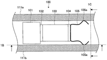
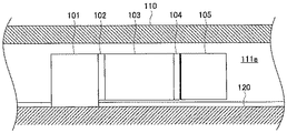
図1A〜図1Cは、駆動装置100を示す平断面図、側断面図および正断面図である。図1A中に示す断面1Bおよび1Cをそれぞれ矢印の向きから見た図が、図1Bおよび図1Cに対応している。駆動装置100は、スムーズインパクト駆動により被駆動体110を駆動する。駆動装置100は、図1A〜図1Cに示すように、固定部101、圧電素子103、一対の押圧体105、被駆動体110、ベース台120、ベアリング125a、125bを備えている。
[Embodiment 1]
(Configuration of drive unit)
1A to 1C are a plan cross-sectional view, a side cross-sectional view, and a front cross-sectional view showing the
固定部101は、ベース台120に固定され、圧電素子103の一端を固定する。圧電素子103は、連結部102により一端を固定部101に固定され、他端は連結部104により一対の押圧体105に連結されている。圧電素子103は、電圧の印加により伸縮し、一対の押圧体105を駆動する。
The
一対の押圧体105は、圧電素子103の他端に設けられ、圧電素子103の伸縮方向に垂直でそれぞれ逆向きに押圧力を有している。すなわち、壁部111a、111bをバランスよく押圧し、摩擦力が生じていることでスムーズインパクト駆動が可能となる。このように、圧電素子103の伸縮の際に駆動側からの押圧力に基づく摩擦を利用しているため、被駆動側の状況に応じて調整がし易くなる。また、圧電素子103の伸縮方向に垂直で対称な方向に押圧力がかかるため、予圧の方向にバランスが取れており、圧電素子103に曲げなどの応力がかかりにくい。したがって、圧電素子103への負担が軽減される。一対の押圧体105には、図1Aに示すように板バネを用いることができ、板バネは壁部111a、111bに対して外向きの弾性力を有している。板バネを用いることにより予圧の強さを容易に調整することができる。また、駆動部分の先端を軽量化することができる。
The pair of
一対の押圧体105は、互いに対称な力で押圧することが好ましい。たとえば、一対の押圧体105の押圧方向は、水平逆向きとし、強さは同じとする。これにより、圧電素子103に曲げ応力がかからず、圧電素子103にかかる負担を低減できる。さらには対称な形状を有していることが好ましい。また、一対の押圧体105は外向きに凸になるように湾曲していることが好ましい。凸状部105aが、壁部111a、111bに当接することで、スムーズインパクト駆動に適した摩擦と滑りの調整が容易になる。
The pair of
被駆動体110は、壁部111a、111bを有しており、ベース台120によりベアリング125a、125bを介して支持されている。一対の壁部111a、111bは、少なくとも互いの間隔が一定であることが好ましく、平行な一直線の壁を形成していることが好ましい。被駆動体110を位置決め用のテーブルに用いることは好適である。ベース台120は、動かない固定された台である。被駆動体110を移動可能に支持している。
The driven
ベアリング125a、125bは、一種のボールベアリングであり、ベース台120に対して被駆動体110を移動可能にしている。なお、微小な制御を可能にするためには、ベアリングを採用することが好ましいが、ベース台120が被駆動体110を移動可能に支持できるのであれば、必ずしもベアリングを用いる必要はない。
The
(駆動装置の動作)
次に、上記のように構成された駆動装置100の動作を説明する。図2Aおよび図2Bは、駆動装置100の動作を示す平断面図である。たとえば、圧電素子103に電圧が印加されると、図2Aに示すように圧電素子103が伸張する。圧電素子103に印加する電圧は、徐々に増加させ、急激には変化させない。その結果、押圧されている壁部111a、111bが滑ることなく一対の押圧体105に追従して移動する。
(Operation of drive unit)
Next, the operation of the
その後、圧電素子103を徐々に伸張させて、所定の電圧に至ると、電圧を急激に下げて圧電素子103を収縮させる。たとえば、電圧の正負を反転させることで急峻な変化を生じさせることができる。その場合には、最も大きい変化幅で急峻な変化を与えることが、スムーズインパクト駆動にとっては効率的である。ただし、必ずしも電圧の正負を反転させる必要はなく、あらかじめ決めた所定値まで電圧を一挙に下げてもよい。そのとき、被駆動体110と一対の押圧体の凸状部105aとの間に滑りが生じ、送られた被駆動体110は慣性によりほぼそのままの状態を維持する。そして、一対の押圧体105は元の位置まで戻る。このようにして、被駆動体110をスムーズインパクト駆動により移動させることができる。
After that, when the
なお、上記の例では、電圧の印加により圧電素子103を徐々に伸張させ、急激に収縮させているが、徐々に収縮させ急激に伸張させる場合であっても同様である。圧電素子103の分極方向にも依存するが、スムーズインパクト駆動を行う場合の印加電圧は、徐々に上げて急激に下げるか、徐々に下げて急激に上げるかのいずれかとなり、時間に対する印加電圧の関係は鋸波型のグラフで表される。
In the above example, the
[実施形態2]
上記の実施形態では、一対の押圧体の例として板バネを挙げているが、一対の押圧体自体には押圧力を付与せず、伸張力のある弾性体を一対の押圧体の間に設けることで各押圧体に押圧力を付与することができる。その場合には、設けられた弾性体の伸張力を利用することで、逆向きの方向の押圧力を生じさせることができる。
[Embodiment 2]
In the above embodiment, a leaf spring is cited as an example of the pair of pressing bodies, but a pressing force is not applied to the pair of pressing bodies themselves, and an elastic body having an extension force is provided between the pair of pressing bodies. Thus, a pressing force can be applied to each pressing body. In that case, a pressing force in the opposite direction can be generated by utilizing the stretching force of the provided elastic body.
図3は、押圧力にコイルバネ230(弾性体)を用いた駆動装置200を示す平断面図である。駆動装置200は、駆動装置100とほぼ同様に構成されているが、駆動装置200では、一対の押圧体105の間にコイルバネ230が設けられている。駆動装置200は、コイルバネ230の弾性力により壁部111a、111bへの押圧力を維持し、スムーズインパクト駆動を可能にしている。通常、壁部111a、111bの一方と圧電素子103との距離が、他方と圧電素子103との距離と異なるアンバランスな状態で駆動すると、圧電素子103に曲げ応力等の負担がかかる。しかし、上記のような構成をとることで、柔軟に押圧力を伝えることができ、圧電素子103に負担を与えることなくスムーズインパクト駆動させることが可能になる。
FIG. 3 is a cross-sectional plan view showing a
[実施形態3]
上記の実施形態では、一対の押圧体105により予圧を得ており、特に被駆動体110側の調整は必要ない。しかし、微調整が必要な場合もあるため、被駆動体110は、一対の押圧体105に対する壁部111a、111bからの予圧を調整できる予圧調整機構340を有していてもよい。図4は、予圧調整機構340を有する駆動装置300を示す平面図である。図4では、模式的にネジのような記号で予圧調整機構340を示している。たとえば、壁部111a、111bの外側にそれぞれもう一つの壁がある場合には、その壁の貫通孔にネジを螺合させ、ねじ込んで貫通させた先端を壁部111a、111bに当てて壁部111a、111bへの圧力を調整することができる。これにより、予圧を微調整することができる。
[Embodiment 3]
In the above embodiment, the preload is obtained by the pair of
[実施形態4]
上記の実施形態では、壁部111a、111bは、平行で直線的に形成されているが、曲線状に形成されていてもよい。図5は、壁部が曲線状に形成された駆動装置400を示す平面図である。図5に示すように、駆動装置400の構成は、駆動装置100の構成とほぼ同様であるが、壁部411a、411bは互いの間隔を一定に保持しつつ曲線状に形成されている。これにより、曲線状の経路に沿った駆動が可能となる。たとえばステージに回転運動や蛇行運動をさせることもできる。ただし正確に駆動させるためには、壁部111a、111bの間隔は一定であることが好ましい。また、この場合には、一対の押圧体105が壁部411a、411bの内面に垂直に当接することが好ましいため、壁部411a、411bが直線状に形成されている場合より間隔を広くとることが好ましい。
[Embodiment 4]
In the above embodiment, the
100 駆動装置
101 固定部
102 連結部
103 圧電素子
104 連結部
105 一対の押圧体
105a 凸状部
110 被駆動体
111a、111b 壁部
120 ベース台
125a、125bベアリング
200 駆動装置
230 コイルバネ
300 駆動装置
340 予圧調整機構
400 駆動装置
411a、411b 壁部
DESCRIPTION OF
Claims (6)
一端を固定され、電圧の印加により伸縮する圧電素子と、
前記圧電素子の他端に設けられ、前記圧電素子の伸縮方向に垂直でそれぞれ逆向きに押圧力を有する一対の押圧体と、
前記一対の押圧体に押圧される一対の壁部を有する被駆動体と、を備え、
前記圧電素子の伸縮により、前記一対の押圧体が前記被駆動体をスムーズインパクト駆動することを特徴とする駆動装置。 A drive device having a smooth impact drive mechanism,
A piezoelectric element that is fixed at one end and expands and contracts by application of a voltage;
A pair of pressing bodies provided at the other end of the piezoelectric element, each having a pressing force perpendicular to the expansion and contraction direction of the piezoelectric element and opposite to each other;
A driven body having a pair of wall portions pressed against the pair of pressing bodies,
The driving device according to claim 1, wherein the pair of pressing bodies smoothly drives the driven body by expansion and contraction of the piezoelectric element.
Priority Applications (1)
| Application Number | Priority Date | Filing Date | Title |
|---|---|---|---|
| JP2009040707A JP5426897B2 (en) | 2009-02-24 | 2009-02-24 | Drive device |
Applications Claiming Priority (1)
| Application Number | Priority Date | Filing Date | Title |
|---|---|---|---|
| JP2009040707A JP5426897B2 (en) | 2009-02-24 | 2009-02-24 | Drive device |
Publications (2)
| Publication Number | Publication Date |
|---|---|
| JP2010200436A true JP2010200436A (en) | 2010-09-09 |
| JP5426897B2 JP5426897B2 (en) | 2014-02-26 |
Family
ID=42824560
Family Applications (1)
| Application Number | Title | Priority Date | Filing Date |
|---|---|---|---|
| JP2009040707A Expired - Fee Related JP5426897B2 (en) | 2009-02-24 | 2009-02-24 | Drive device |
Country Status (1)
| Country | Link |
|---|---|
| JP (1) | JP5426897B2 (en) |
Cited By (1)
| Publication number | Priority date | Publication date | Assignee | Title |
|---|---|---|---|---|
| CN113746366A (en) * | 2021-09-18 | 2021-12-03 | 上海隐冠半导体技术有限公司 | Piezoelectric inertia driving device |
Citations (7)
| Publication number | Priority date | Publication date | Assignee | Title |
|---|---|---|---|---|
| JPH02228265A (en) * | 1989-02-28 | 1990-09-11 | Okuma Mach Works Ltd | Linear actuator drive controller |
| JPH06186485A (en) * | 1992-12-22 | 1994-07-08 | Olympus Optical Co Ltd | Quickly deformable piezoelectric actuator |
| JPH0795782A (en) * | 1993-09-21 | 1995-04-07 | Seiko Instr Inc | Two-dimensional travelling mechanism |
| JPH11191967A (en) * | 1997-12-25 | 1999-07-13 | Minolta Co Ltd | Driver |
| JP2004153999A (en) * | 2004-01-21 | 2004-05-27 | Olympus Corp | Piezoelectric actuator |
| JP2008220097A (en) * | 2007-03-06 | 2008-09-18 | Fujinon Corp | Drive arrangement |
| JP2008220171A (en) * | 2004-06-24 | 2008-09-18 | Miniswys Sa | Drive device |
-
2009
- 2009-02-24 JP JP2009040707A patent/JP5426897B2/en not_active Expired - Fee Related
Patent Citations (7)
| Publication number | Priority date | Publication date | Assignee | Title |
|---|---|---|---|---|
| JPH02228265A (en) * | 1989-02-28 | 1990-09-11 | Okuma Mach Works Ltd | Linear actuator drive controller |
| JPH06186485A (en) * | 1992-12-22 | 1994-07-08 | Olympus Optical Co Ltd | Quickly deformable piezoelectric actuator |
| JPH0795782A (en) * | 1993-09-21 | 1995-04-07 | Seiko Instr Inc | Two-dimensional travelling mechanism |
| JPH11191967A (en) * | 1997-12-25 | 1999-07-13 | Minolta Co Ltd | Driver |
| JP2004153999A (en) * | 2004-01-21 | 2004-05-27 | Olympus Corp | Piezoelectric actuator |
| JP2008220171A (en) * | 2004-06-24 | 2008-09-18 | Miniswys Sa | Drive device |
| JP2008220097A (en) * | 2007-03-06 | 2008-09-18 | Fujinon Corp | Drive arrangement |
Cited By (1)
| Publication number | Priority date | Publication date | Assignee | Title |
|---|---|---|---|---|
| CN113746366A (en) * | 2021-09-18 | 2021-12-03 | 上海隐冠半导体技术有限公司 | Piezoelectric inertia driving device |
Also Published As
| Publication number | Publication date |
|---|---|
| JP5426897B2 (en) | 2014-02-26 |
Similar Documents
| Publication | Publication Date | Title |
|---|---|---|
| Ho et al. | A piezoelectric motor for precision positioning applications | |
| US7567012B2 (en) | Drive unit | |
| JP5022705B2 (en) | Rolled electroactive polymer | |
| CN106849743B (en) | Stick-slip linear actuator based on piezoelectric fabric | |
| JP2014018027A (en) | Vibration type actuator, imaging apparatus, and stage | |
| Yong | A new preload mechanism for a high-speed piezoelectric stack nanopositioner | |
| Yokose et al. | Resonance frequency ratio control with an additional inductor for a miniaturized resonant-type SIDM actuator | |
| KR100777630B1 (en) | Driving machanism | |
| JP5387811B2 (en) | Driving method of driving device | |
| JP5426897B2 (en) | Drive device | |
| US10510944B2 (en) | Vibration actuator reduced in cost and size, and electronic device | |
| JP6021559B2 (en) | Vibration type driving device and imaging device | |
| US20120228996A1 (en) | Driving apparatus | |
| JP6650637B2 (en) | Actuator and stage device | |
| JP6638124B2 (en) | Stage device and drive mechanism used for same | |
| KR100957190B1 (en) | Stage device using piezoelectric linear motor | |
| JP2016032351A (en) | Vibration type actuator, optical equipment, and imaging apparatus | |
| JPH07274543A (en) | Driving gear using electromechanical transducer | |
| CN206759337U (en) | Stick-slip linear actuator based on piezoelectric fabric | |
| CN116015097B (en) | Piezoelectric driving assembly, rotary motor and electronic device | |
| WO2019159389A1 (en) | Vibration actuator | |
| CN104578898B (en) | Inertial piezoelectric ultrasonic motor and control method thereof | |
| JP6145674B2 (en) | Actuator | |
| JP2007336623A (en) | Drive device | |
| KR100710140B1 (en) | Nano Positioning Actuator |
Legal Events
| Date | Code | Title | Description |
|---|---|---|---|
| A621 | Written request for application examination |
Free format text: JAPANESE INTERMEDIATE CODE: A621 Effective date: 20120104 |
|
| A977 | Report on retrieval |
Free format text: JAPANESE INTERMEDIATE CODE: A971007 Effective date: 20130529 |
|
| A131 | Notification of reasons for refusal |
Free format text: JAPANESE INTERMEDIATE CODE: A131 Effective date: 20130604 |
|
| A521 | Request for written amendment filed |
Free format text: JAPANESE INTERMEDIATE CODE: A523 Effective date: 20130705 |
|
| TRDD | Decision of grant or rejection written | ||
| A01 | Written decision to grant a patent or to grant a registration (utility model) |
Free format text: JAPANESE INTERMEDIATE CODE: A01 Effective date: 20131126 |
|
| A61 | First payment of annual fees (during grant procedure) |
Free format text: JAPANESE INTERMEDIATE CODE: A61 Effective date: 20131129 |
|
| R150 | Certificate of patent or registration of utility model |
Free format text: JAPANESE INTERMEDIATE CODE: R150 Ref document number: 5426897 Country of ref document: JP Free format text: JAPANESE INTERMEDIATE CODE: R150 |
|
| S111 | Request for change of ownership or part of ownership |
Free format text: JAPANESE INTERMEDIATE CODE: R313113 |
|
| R350 | Written notification of registration of transfer |
Free format text: JAPANESE INTERMEDIATE CODE: R350 |
|
| S111 | Request for change of ownership or part of ownership |
Free format text: JAPANESE INTERMEDIATE CODE: R313113 |
|
| R350 | Written notification of registration of transfer |
Free format text: JAPANESE INTERMEDIATE CODE: R350 |
|
| R250 | Receipt of annual fees |
Free format text: JAPANESE INTERMEDIATE CODE: R250 |
|
| R250 | Receipt of annual fees |
Free format text: JAPANESE INTERMEDIATE CODE: R250 |
|
| R250 | Receipt of annual fees |
Free format text: JAPANESE INTERMEDIATE CODE: R250 |
|
| R250 | Receipt of annual fees |
Free format text: JAPANESE INTERMEDIATE CODE: R250 |
|
| R250 | Receipt of annual fees |
Free format text: JAPANESE INTERMEDIATE CODE: R250 |
|
| R250 | Receipt of annual fees |
Free format text: JAPANESE INTERMEDIATE CODE: R250 |
|
| S531 | Written request for registration of change of domicile |
Free format text: JAPANESE INTERMEDIATE CODE: R313531 |
|
| R350 | Written notification of registration of transfer |
Free format text: JAPANESE INTERMEDIATE CODE: R350 |
|
| R250 | Receipt of annual fees |
Free format text: JAPANESE INTERMEDIATE CODE: R250 |
|
| LAPS | Cancellation because of no payment of annual fees |