JP2010200907A - Bed - Google Patents
Bed Download PDFInfo
- Publication number
- JP2010200907A JP2010200907A JP2009048380A JP2009048380A JP2010200907A JP 2010200907 A JP2010200907 A JP 2010200907A JP 2009048380 A JP2009048380 A JP 2009048380A JP 2009048380 A JP2009048380 A JP 2009048380A JP 2010200907 A JP2010200907 A JP 2010200907A
- Authority
- JP
- Japan
- Prior art keywords
- bed
- hole
- horizontal
- vertical hole
- screw
- Prior art date
- Legal status (The legal status is an assumption and is not a legal conclusion. Google has not performed a legal analysis and makes no representation as to the accuracy of the status listed.)
- Pending
Links
- 208000019901 Anxiety disease Diseases 0.000 description 2
- 230000036506 anxiety Effects 0.000 description 2
Images




Classifications
-
- A—HUMAN NECESSITIES
- A47—FURNITURE; DOMESTIC ARTICLES OR APPLIANCES; COFFEE MILLS; SPICE MILLS; SUCTION CLEANERS IN GENERAL
- A47C—CHAIRS; SOFAS; BEDS
- A47C31/00—Details or accessories for chairs, beds, or the like, not provided for in other groups of this subclass, e.g. upholstery fasteners, mattress protectors, stretching devices for mattress nets
- A47C31/002—Anti-earthquake means
-
- A—HUMAN NECESSITIES
- A47—FURNITURE; DOMESTIC ARTICLES OR APPLIANCES; COFFEE MILLS; SPICE MILLS; SUCTION CLEANERS IN GENERAL
- A47C—CHAIRS; SOFAS; BEDS
- A47C19/00—Bedsteads
- A47C19/20—Multi-stage bedsteads; Bedsteads stackable to multi-stage bedsteads
-
- A—HUMAN NECESSITIES
- A47—FURNITURE; DOMESTIC ARTICLES OR APPLIANCES; COFFEE MILLS; SPICE MILLS; SUCTION CLEANERS IN GENERAL
- A47C—CHAIRS; SOFAS; BEDS
- A47C19/00—Bedsteads
- A47C19/20—Multi-stage bedsteads; Bedsteads stackable to multi-stage bedsteads
- A47C19/202—Stacking or nesting bedsteads
Landscapes
- Business, Economics & Management (AREA)
- Engineering & Computer Science (AREA)
- Emergency Management (AREA)
- Environmental & Geological Engineering (AREA)
- Invalid Beds And Related Equipment (AREA)
Abstract
Description
本発明は、ベッドに関する。 The present invention relates to a bed.
従来、上ベッドの4隅の上支柱と下ベッドの4隅の下支柱とを相互に連結する支柱連結構造を備えたベッドに於て、支柱連結構造には、連結ピンが用いられている(例えば、特許文献1参照)。 2. Description of the Related Art Conventionally, in a bed provided with a strut connection structure that interconnects the upper struts at the four corners of the upper bed and the lower struts at the four corners of the lower bed, a connection pin is used for the strut connection structure ( For example, see Patent Document 1).
しかし、連結ピンは丸棒という単純な形状であって、ベッドに振動が加わると上下ベッドががたがたと音がするという欠点があった。そして、ベッドを使用するにあたり、不安感を与えるという欠点があった。特に、地震に対して不安を抱かせるものであった。 However, the connecting pin has a simple shape of a round bar, and there is a drawback that when the bed is vibrated, the upper and lower beds rattle. And there was the fault of giving an anxiety in using a bed. In particular, they were anxious about the earthquake.
解決しようとする課題は、ベッドに振動が加わると上下ベッドががたがたと音がする点である。そして、ベッドを使用するにあたり、不安感を与える点である。特に、地震に対して不安を抱かせる点である。 The problem to be solved is that when the bed is vibrated, the upper and lower beds make a rattling sound. And it is a point that gives anxiety when using the bed. In particular, it is a point of concern for earthquakes.
そこで、本発明に係るベッドは、上ベッドの4隅の上支柱と、下ベッドの4隅の下支柱とを相互に連結する支柱連結構造を備えたベッドに於て、上記上支柱の下端面から第1縦孔を形成し、かつ、上記下支柱の上端面から第2縦孔を形成し、上端及び下端に横ネジ孔を設けた丸棒状の連結ピンを、上記第1縦孔と第2縦孔に挿入し、かつ、上記上支柱の第1縦孔に通ずる第1横孔を形成し、かつ、上記下支柱の第2縦孔に通ずる第2横孔を形成し、ネジを上記第1横孔及び第2横孔の各々から挿入して、上記連結ピンの横ネジ孔に螺着するものである。
また、上記第1横孔は、上記上支柱の横断面の長辺側でかつベッド内面側から形成され、かつ、上記第2横孔は、上記下支柱の横断面の長辺側でかつベッド内面側から形成されているものである。
Therefore, the bed according to the present invention is a bed provided with a strut connection structure that interconnects the upper struts of the four corners of the upper bed and the lower struts of the four corners of the lower bed, and the lower end surface of the upper strut The first vertical hole is formed, and the second vertical hole is formed from the upper end surface of the lower support column, and the round bar-shaped connecting pin having the horizontal screw holes at the upper end and the lower end is connected to the first vertical hole and the first vertical hole. A first horizontal hole that is inserted into the two vertical holes and communicates with the first vertical hole of the upper column, and a second horizontal hole that communicates with the second vertical hole of the lower column is formed; It is inserted from each of the first horizontal hole and the second horizontal hole and screwed into the horizontal screw hole of the connecting pin.
The first horizontal hole is formed on the long side of the cross section of the upper column and the bed inner surface side, and the second horizontal hole is on the long side of the cross section of the lower column and the bed. It is formed from the inner surface side.
本発明のベッドによれば、ベッドに振動が加わった際にがたつき音が発生することを防止できる。そして、安全性に優れ、ベッドを使用する人に安心感を与えることができる。さらに、地震対策となる。また、外観上スマートである。 According to the bed of the present invention, it is possible to prevent the rattling sound from being generated when vibration is applied to the bed. And it is excellent in safety and can give a sense of security to the person using the bed. Furthermore, it will be an earthquake countermeasure. Moreover, it is smart in appearance.
図1・図2は、本発明の実施の一形態を示す。このベッドは、上ベッド1の4隅の上支柱2と、下ベッド3の4隅の下支柱4とを相互に連結する支柱連結構造Wを備えている。支柱連結構造Wは、次のように構成される。
1 and 2 show an embodiment of the present invention. This bed includes a column connection structure W that connects the
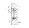
図3〜図6(図3は図1の部分Cを矢印A方向から見た要部拡大図である。)に示すように、上支柱2の下端面5から第1縦孔6が形成され、かつ、下支柱4の上端面7から第2縦孔8が形成されている。上支柱2の第1縦孔6に通ずる第1横孔9が形成され、かつ、下支柱4の第2縦孔8に通ずる第2横孔10が形成されている。第1横孔9は、上支柱2の横断面の長辺11側でかつベッド内面E側から形成され、かつ、第2横孔10は、下支柱4の横断面の長辺12側でかつベッド内面E側から形成されている。
As shown in FIG. 3 to FIG. 6 (FIG. 3 is an enlarged view of the main part of the portion C of FIG. 1 viewed from the direction of arrow A), the first
図7・図8に示すように、上端13及び下端14に横ネジ孔15を設けた丸棒状の連結ピン16を、備える。連結ピン16の横ネジ孔15は、貫通しており、軸心を含む一縦断面に関して対称状となっている。これにより、連結ピン16を軸心廻りに180°回転させた向きとしても使用することができ、至便である。連結ピン16は、横ネジ孔15の開口部17に誘導勾配面18を有する。誘導勾配面18により、後述のようにネジ19(図3〜図6参照)を挿入する際、ネジ19の先端部20が誘導されてネジ19を容易・迅速に挿入することができる。
As shown in FIGS. 7 and 8, a round bar-like connecting
上ベッド1と下ベッド3を連結するには、図3〜図6に示すように、連結ピン16を、第1縦孔6と第2縦孔8に挿入する。その後、ネジ19を第1横孔9及び第2横孔10の各々から挿入して、連結ピン16の横ネジ孔15に螺着する。
In order to connect the
なお、本発明は、設計変更可能であって、例えば、全体が3段ベッドであっても良い、この場合、相互に連結される2つのベッド部に注目して上側のベッドを上ベッド1、下側のベッドを下ベッド3とみなす。
The present invention can be modified in design, for example, the whole may be a three-stage bed. In this case, paying attention to two bed parts connected to each other, the upper bed is the
以上のように、本発明は、上ベッド1の4隅の上支柱2と、下ベッド3の4隅の下支柱4とを相互に連結する支柱連結構造Wを備えたベッドに於て、上支柱2の下端面5から第1縦孔6を形成し、かつ、下支柱4の上端面7から第2縦孔8を形成し、上端13及び下端14に横ネジ孔15を設けた丸棒状の連結ピン16を、第1縦孔6と第2縦孔8に挿入し、かつ、上支柱2の第1縦孔6に通ずる第1横孔9を形成し、かつ、下支柱4の第2縦孔8に通ずる第2横孔10を形成し、ネジ19を第1横孔9及び第2横孔10の各々から挿入して、連結ピン16の横ネジ孔15に螺着するので、ベッドに振動が加わった際にがたつき音が発生することを防止できる。そして、安全性に優れ、ベッドを使用する人に安心感を与えることができる。さらに、上ベッド1が脱落する危険性を無くして、地震対策となる。
As described above, according to the present invention, in the bed provided with the strut connection structure W that interconnects the
また、第1横孔9は、上支柱2の横断面の長辺11側でかつベッド内面E側から形成され、かつ、第2横孔10は、下支柱4の横断面の長辺12側でかつベッド内面E側から形成されているので、外観上スマートである。
The first
1 上ベッド
2 上支柱
3 下ベッド
4 下支柱
5 下端面
6 第1縦孔
7 上端面
8 第2縦孔
9 第1横孔
10 第2横孔
11 長辺
12 長辺
13 上端
14 下端
15 横ネジ孔
16 連結ピン
19 ネジ
E ベッド内面
DESCRIPTION OF
10 Second side hole
11 Long side
12 Long side
13 Top
14 Bottom
15 Horizontal screw hole
16 Connecting pin
19 Screw E Bed inside
Claims (2)
上記上支柱(2)の下端面(5)から第1縦孔(6)を形成し、かつ、上記下支柱(4)の上端面(7)から第2縦孔(8)を形成し、上端(13)及び下端(14)に横ネジ孔(15)を設けた丸棒状の連結ピン(16)を、上記第1縦孔(6)と第2縦孔(8)に挿入し、かつ、上記上支柱(2)の第1縦孔(6)に通ずる第1横孔(9)を形成し、かつ、上記下支柱(4)の第2縦孔(8)に通ずる第2横孔(10)を形成し、ネジ(19)を上記第1横孔(9)及び第2横孔(10)の各々から挿入して、上記連結ピン(16)の横ネジ孔(15)に螺着することを特徴とするベッド。 In a bed provided with a strut connection structure (W) for interconnecting the upper struts (2) at the four corners of the upper bed (1) and the lower struts (4) at the four corners of the lower bed (3),
Forming a first vertical hole (6) from the lower end surface (5) of the upper support column (2), and forming a second vertical hole (8) from the upper end surface (7) of the lower support column (4); Insert a round bar-like connecting pin (16) having a horizontal screw hole (15) at the upper end (13) and the lower end (14) into the first vertical hole (6) and the second vertical hole (8), and Forming a first horizontal hole (9) communicating with the first vertical hole (6) of the upper column (2) and communicating with the second vertical hole (8) of the lower column (4) (10) is formed, and a screw (19) is inserted from each of the first lateral hole (9) and the second lateral hole (10), and screwed into the lateral screw hole (15) of the connecting pin (16). A bed characterized by wearing.
Priority Applications (1)
| Application Number | Priority Date | Filing Date | Title |
|---|---|---|---|
| JP2009048380A JP2010200907A (en) | 2009-03-02 | 2009-03-02 | Bed |
Applications Claiming Priority (1)
| Application Number | Priority Date | Filing Date | Title |
|---|---|---|---|
| JP2009048380A JP2010200907A (en) | 2009-03-02 | 2009-03-02 | Bed |
Publications (1)
| Publication Number | Publication Date |
|---|---|
| JP2010200907A true JP2010200907A (en) | 2010-09-16 |
Family
ID=42963032
Family Applications (1)
| Application Number | Title | Priority Date | Filing Date |
|---|---|---|---|
| JP2009048380A Pending JP2010200907A (en) | 2009-03-02 | 2009-03-02 | Bed |
Country Status (1)
| Country | Link |
|---|---|
| JP (1) | JP2010200907A (en) |
Cited By (1)
| Publication number | Priority date | Publication date | Assignee | Title |
|---|---|---|---|---|
| DK201600644A1 (en) * | 2016-10-18 | 2018-05-07 | Jensen Furn Aps | Bed entry for bunk and loft beds |
Citations (3)
| Publication number | Priority date | Publication date | Assignee | Title |
|---|---|---|---|---|
| JPS627504U (en) * | 1985-07-01 | 1987-01-17 | ||
| JPH07150638A (en) * | 1993-10-07 | 1995-06-13 | Kaneko Seisakusho:Kk | Connecting structure for column and horizontal member in wooden building |
| JP2008023301A (en) * | 2006-07-25 | 2008-02-07 | Shimooka:Kk | Connector for bunk bed |
-
2009
- 2009-03-02 JP JP2009048380A patent/JP2010200907A/en active Pending
Patent Citations (3)
| Publication number | Priority date | Publication date | Assignee | Title |
|---|---|---|---|---|
| JPS627504U (en) * | 1985-07-01 | 1987-01-17 | ||
| JPH07150638A (en) * | 1993-10-07 | 1995-06-13 | Kaneko Seisakusho:Kk | Connecting structure for column and horizontal member in wooden building |
| JP2008023301A (en) * | 2006-07-25 | 2008-02-07 | Shimooka:Kk | Connector for bunk bed |
Cited By (1)
| Publication number | Priority date | Publication date | Assignee | Title |
|---|---|---|---|---|
| DK201600644A1 (en) * | 2016-10-18 | 2018-05-07 | Jensen Furn Aps | Bed entry for bunk and loft beds |
Similar Documents
| Publication | Publication Date | Title |
|---|---|---|
| US10349751B2 (en) | Bunk bed frame | |
| US11071392B2 (en) | Structure for connecting a stand pole and a beam of a bunk bed and a bunk bed using the structure | |
| JP2010200907A (en) | Bed | |
| JP2017131632A (en) | Bracket assembly | |
| JP4590478B2 (en) | Assembly shelf | |
| KR20140110359A (en) | Lower part and upper part pipe connecting structure of fixing pole | |
| KR101894269B1 (en) | Frame connector | |
| KR100965297B1 (en) | Device for supporting a bed mattress | |
| CN103137106A (en) | Integrated type violin sound system | |
| KR20140005570U (en) | A pipe supporter for green house | |
| JP2016087260A (en) | Desktop frame, covering device, and desk system | |
| CN201106602Y (en) | connector for table | |
| CN104112315A (en) | Support structure of vending machine | |
| KR20140005380U (en) | Bar fixing apparatus of fence | |
| JP6557818B2 (en) | Adapter for connecting unit members | |
| CN203118428U (en) | Integrated violin sound system | |
| JP3216779U (en) | Handrail device and pedestal part of handrail device | |
| KR20130004809U (en) | Lower part and upper part pipe connecting structure of fixing pole | |
| CN104787231B (en) | A kind of ship storehouse steel plate base | |
| CN209603826U (en) | Multifunctional stainless steel decorative anti-theft net | |
| CN201403911Y (en) | Connecting structure between screens | |
| JP2008023301A (en) | Connector for bunk bed | |
| CN107626152A (en) | A kind of novel metal screen pack | |
| CN107774033A (en) | A kind of small area metal filter screen | |
| JP2011038357A (en) | Handrail |
Legal Events
| Date | Code | Title | Description |
|---|---|---|---|
| A977 | Report on retrieval |
Free format text: JAPANESE INTERMEDIATE CODE: A971007 Effective date: 20120213 |
|
| A131 | Notification of reasons for refusal |
Free format text: JAPANESE INTERMEDIATE CODE: A131 Effective date: 20120221 |
|
| A02 | Decision of refusal |
Free format text: JAPANESE INTERMEDIATE CODE: A02 Effective date: 20120724 |