JP2010201364A - Air filter - Google Patents
Air filter Download PDFInfo
- Publication number
- JP2010201364A JP2010201364A JP2009050691A JP2009050691A JP2010201364A JP 2010201364 A JP2010201364 A JP 2010201364A JP 2009050691 A JP2009050691 A JP 2009050691A JP 2009050691 A JP2009050691 A JP 2009050691A JP 2010201364 A JP2010201364 A JP 2010201364A
- Authority
- JP
- Japan
- Prior art keywords
- beam member
- movement
- suction nozzle
- suction
- air filter
- Prior art date
- Legal status (The legal status is an assumption and is not a legal conclusion. Google has not performed a legal analysis and makes no representation as to the accuracy of the status listed.)
- Pending
Links
Images


Landscapes
- Filtering Of Dispersed Particles In Gases (AREA)
Abstract
Description
本発明は、ケーシングに固定された集塵フィルタに付着した塵埃を吸込み口から吸引除去する吸引ノズルを、左右方向、及び、上方向に移動させて、前記塵埃の吸引除去を実行するエアフィルタ装置に関する。 The present invention relates to an air filter device that performs suction and removal of dust by moving a suction nozzle that sucks and removes dust adhering to a dust collection filter fixed to a casing from a suction port in a horizontal direction and an upward direction. About.
近年、ビルや地下鉄、工場などの空調用に、集塵フィルタに付着した塵埃を吸引ノズルで自動的に吸引除去(以降清掃と称する場合がある)するようにした自動クリーニング機能付エアフィルタ装置が広く利用されている(例えば、特許文献1参照)。
このようなエアフィルタ装置は、集塵フィルタの洗浄・交換等の保守作業の必要がなく、集塵フィルタが塵埃の付着量が少ない状態に常時保たれるため、塵埃の捕集効率が安定するという利点がある。
2. Description of the Related Art In recent years, an air filter device with an automatic cleaning function that automatically sucks and removes dust adhering to a dust collecting filter with a suction nozzle (hereinafter sometimes referred to as cleaning) for air conditioning in buildings, subways, factories, etc. Widely used (see, for example, Patent Document 1).
Such an air filter device does not require maintenance work such as cleaning and replacement of the dust collecting filter, and the dust collecting filter is always kept in a state where the amount of dust adhering is small, so that dust collecting efficiency is stabilized. There is an advantage.
例えば、特許文献1に開示のエアフィルタ装置は、正面視四角形のケーシングと、ケーシングの中央開口部に組み付けられる集塵フィルタと、ケーシングの左右両側部に配される昇降ガイドレールに沿って案内される横梁部材と、横梁部材を昇降駆動する昇降移動用駆動手段と、集塵フィルタに吸込み口を臨ませた状態で左右方向に移動自在な状態で横梁部材に保持される吸引ノズルと、横梁部材に内設され、吸引ノズルを左右方向に往復駆動する左右移動用駆動手段と、昇降移動用駆動手段と左右移動用駆動手段との作動を制御する制御手段とを備えて構成されている。
For example, the air filter device disclosed in
そして、吸引ノズルがフレキシブルホースや配管継手等を介して吸引装置に接続されており、この吸引装置が作動している状態で、上記エアフィルタ装置が吸引ノズルを左右移動用駆動手段にて左右方向に移動させ、且つ、昇降移動用駆動手段にて上下方向に移動させることにより、集塵フィルタに付着した塵埃を除去して、この集塵フィルタを清掃できるように構成されている。 The suction nozzle is connected to the suction device via a flexible hose, a pipe joint, etc., and the air filter device moves the suction nozzle in the left-right direction with the left-right movement drive means while the suction device is operating. The dust collecting filter can be cleaned by removing the dust adhering to the dust collecting filter by moving it up and down and moving it up and down by the driving means for moving up and down.
このようなエアフィルタ装置は、例えば、吸引装置の作動音が大きいこと等の理由により、工場や地下鉄等の操業が停止している間(例えば夜間等)に清掃を実行することが多い。従って、装置を信頼性の高いものとするとともに、合理的で無駄のないクリーニングを自動的に行えるエアフィルタ装置とする必要がある。 Such an air filter device often performs cleaning while the operation of a factory, a subway, or the like is stopped (for example, at night) due to, for example, a large operating sound of the suction device. Therefore, it is necessary to make the apparatus highly reliable and to be an air filter apparatus capable of automatically performing rational and lean cleaning.
〔信頼性の確保〕
例えば、集塵フィルタの全面を清掃しながらその清掃時間を極力短くするために、エアフィルタ装置に吸引ノズルの位置を検出するセンサ類(例えば、リミットスイッチやエンコーダ等)を設け、このセンサ類により吸引ノズルの現在位置を検出して、集塵フィルタにおける一つの角部をクリーニングの開始位置としその対角となる角部がクリーニングの終了位置となるように、吸引ノズルを移動操作する構成が考えられる。
しかしながら、エアフィルタ装置の内部は塵埃がたまり易いものであるため、センサ類に塵埃が堆積或いは付着して吸引ノズルの現在の位置の正確な検出が困難となり易く、また、それらを補修する等のメンテナンスも必要となる等、使い勝手の悪いものとなる。
[Ensuring reliability]
For example, in order to shorten the cleaning time as much as possible while cleaning the entire surface of the dust collection filter, the air filter device is provided with sensors (for example, a limit switch and an encoder) for detecting the position of the suction nozzle. A configuration is considered in which the current position of the suction nozzle is detected, and the suction nozzle is moved so that one corner of the dust collection filter is the cleaning start position and the opposite corner is the cleaning end position. It is done.
However, since the dust inside the air filter device is likely to accumulate, it is difficult to accurately detect the current position of the suction nozzle due to the accumulation or adhesion of the dust on the sensors, and repairing them, etc. Maintenance becomes necessary and it becomes inconvenient.
〔無駄のないクリーニング〕
また、例えば、エアフィルタ装置に上記のようなセンサ類を使用せず、タイマによって吸引ノズルが左右移動に要する時間と上下移動に要する時間とを管理して、集塵フィルタの全面を清掃するに要する所定時間の間、吸引ノズルを左右及び上下に移動操作するようにして、集塵フィルタを清掃する構成を採用することも考えられている。
しかしながら、エアフィルタ装置をそのように構成した場合、吸引ノズルの現在の位置を把握することが困難となり、吸引ノズルの移動の開始位置及び終了位置を特定することができず、以下のような問題を生じるおそれがある。
[Cleaning without waste]
In addition, for example, the above-described sensors are not used in the air filter device, and the entire time of the dust collection filter is cleaned by managing the time required for the suction nozzle to move left and right and the time required for vertical movement by a timer. It is also considered to adopt a configuration in which the dust collection filter is cleaned by moving the suction nozzle to the left and right and up and down for a predetermined time required.
However, when the air filter device is configured as such, it becomes difficult to grasp the current position of the suction nozzle, and the start position and the end position of the movement of the suction nozzle cannot be specified. May occur.
上記所定時間としての集塵フィルタ103の全面をクリーニングするのに必要な時間を単位クリーニングの時間とすると、その最小時間は、吸引ノズルを左右方向でフィルタ103の片側端から反対側端まで(例えば左側端から右側端まで)、つまり左右方向に片道分の距離の移動操作をし、その左右方向の移動操作の後に、吸引ノズルを所定の高さ移動させることを順次繰り返しながら、吸引ノズルをフィルタ103の上下方向の片側端から反対側端まで(例えば下端から上端まで)、つまり上下方向に片道分の距離の移動操作をして、集塵フィルタ103を清掃するのに要する時間である。
このように移動操作する場合において、図6(a)に示すように、集塵フィルタ103の最上部あるいは最下部から離れた開始位置(図6(a)におけるSの位置)からクリーニングを開始する形態で、集塵フィルタ103の最上部方向に上記最小時間だけクリーニングした場合、集塵フィルタ103の全面(特に、開始位置Sよりも下部領域の集塵フィルタ103)をクリーニングできないものとなる。尚、図6(a)では集塵フィルタ103の左右方向の端部から離れた位置からクリーニングを開始しているが、吸引ノズルを左右方向で片道分の距離だけ移動操作させる場合には、さらに左右方向においてもクリーニングされていない部分が残るものとなる。
一方、単位クリーニングの時間を上記最小時間の2倍の時間として、この最小時間の2倍の時間の間クリーニングした場合、吸引ノズルは左右方向に片道分、且つ、上下方向に往復分の移動操作をすることとなり、図6(b)に示すように、集塵フィルタ103の上下方向にて全面のクリーニングを行うことができるものの、クリーニングの完了に長い時間を要するものとなる。
ここで、吸引ノズルを、集塵フィルタ103の左右方向で往復分の距離だけ移動操作させ、且つ、集塵フィルタ103の上下方向で往復分の距離だけ移動操作させるようにすれば、集塵フィルタ103の全面を漏れなくクリーニングできるものとなるが、この場合、単位クリーニングの時間として上記最小時間の4倍の時間を要することとなり、クリーニングの完了にさらに長い時間を要するものとなる。
Assuming that the time required for cleaning the entire surface of the
In the case of such a moving operation, as shown in FIG. 6A, the cleaning is started from the start position (the position of S in FIG. 6A) away from the uppermost part or the lowermost part of the
On the other hand, when the unit cleaning time is set to twice the minimum time, and the cleaning is performed for twice the minimum time, the suction nozzle is moved one way in the left-right direction and reciprocated in the up-down direction. As shown in FIG. 6B, although the entire surface can be cleaned in the vertical direction of the
Here, if the suction nozzle is moved by a distance corresponding to the reciprocation in the left-right direction of the
本発明は、上記の課題に鑑みてなされたものであり、その目的は、装置を信頼性の高いものとするとともに、合理的で無駄のないクリーニングを自動的に行えるエアフィルタ装置を得ることにある。 The present invention has been made in view of the above problems, and an object of the present invention is to obtain an air filter device that can automatically perform rational and wasteless cleaning while making the device highly reliable. is there.
上記目的を達成するための本発明に係るエアフィルタ装置の
特徴構成は、ケーシングに固定された集塵フィルタに付着した塵埃を吸込み口から吸引除去する吸引ノズルと、前記吸引ノズルを左右方向に移動自在に保持し且つ前記ケーシングの上下方向に移動自在に保持される横梁部材と、前記吸引ノズルを左右方向に移動操作する左右移動用駆動手段と、前記横梁部材を上方向に移動操作する上昇移動用駆動手段と、前記左右移動用駆動手段にて前記吸引ノズルを左右方向に往復移動させ、且つ、前記上昇移動用駆動手段にて前記横梁部材を上方向に移動させて前記塵埃の吸引除去を実行させる制御手段とが設けられ、
前記制御手段が、前記吸引ノズルの左右移動及び前記横梁部材の上昇移動に伴って前記塵埃の吸引除去を実行する吸引除去制御を実行した後、前記上昇移動用駆動手段による前記横梁部材の上下方向位置保持を解除して、前記横梁部材を前記ケーシングの最下部に移動させる横梁復帰制御を実行する点にある。
In order to achieve the above object, the air filter device according to the present invention is characterized by a suction nozzle that sucks and removes dust adhering to a dust collection filter fixed to a casing from a suction port, and moves the suction nozzle in the left-right direction. A horizontal beam member that is freely held and is movable in the vertical direction of the casing, a left / right drive means for moving the suction nozzle in the left / right direction, and an upward movement for moving the horizontal beam member in the upward direction The suction nozzle is reciprocated in the left-right direction by the drive means for moving and the drive means for moving left and right, and the horizontal beam member is moved upward by the drive means for lifting movement to remove the dust by suction. Control means to be executed,
After the control means performs suction removal control for performing suction removal of the dust in accordance with the lateral movement of the suction nozzle and the upward movement of the horizontal beam member, the vertical direction of the horizontal beam member by the upward movement drive means The position holding is released and the transverse beam return control for moving the transverse beam member to the lowermost part of the casing is executed.
上記特徴構成によれば、吸引ノズルの左右移動及び横梁部材の上昇移動に伴って塵埃の吸引除去を実行する吸引除去制御を実行した後、上昇移動用駆動手段による横梁部材の上下方向位置保持を解除する事によって、横梁部材は例えば自重によりケーシングの最下部、つまり、集塵フィルタの最下部に移動する。すなわち、塵埃の吸引除去が終了したときには、その都度、横梁部材に保持された吸引ノズルは集塵フィルタの最下部に移動されることとなり、その集塵フィルタの最下部にて、次の清掃に備えて待機する状態となる。 According to the above characteristic configuration, after the suction removal control for performing the suction removal of the dust in accordance with the horizontal movement of the suction nozzle and the upward movement of the horizontal beam member is performed, the vertical beam position holding of the horizontal beam member by the upward movement driving means is performed. By releasing, the cross beam member moves to the lowermost part of the casing, that is, the lowermost part of the dust collecting filter, for example, by its own weight. That is, each time the dust removal is completed, the suction nozzle held by the cross beam member is moved to the lowermost part of the dust collecting filter, and the next cleaning is performed at the lowermost part of the dust collecting filter. It will be in a state of preparing and waiting.
そして、次回の清掃においては、常に集塵フィルタの最下部から吸引ノズルの上昇移動を開始させることとなるので、吸引ノズルが集塵フィルタの最下部から最上部まで移動するために必要な最小限の時間(少なくとも上下方向の移動に関し片道分の時間)である単位クリーニングの時間だけ吸引ノズルによる清掃を実行することにより、集塵フィルタを清掃することができることとなる。
従って、吸引ノズルの位置を検出するセンサを使わない構成としながらも、極力短い時間で集塵フィルタ全面を清掃することが可能となるエアフィルタ装置を提供することができ、信頼性が高く、且つ、合理的で無駄のないクリーニングを自動的に行えるエアフィルタ装置が得られるものとなった。
In the next cleaning, the suction nozzle always starts to move upward from the bottom of the dust collection filter, so the minimum necessary for the suction nozzle to move from the bottom to the top of the dust collection filter. The dust collection filter can be cleaned by executing the cleaning by the suction nozzle for the unit cleaning time which is the time (at least one way for the vertical movement).
Accordingly, it is possible to provide an air filter device that can clean the entire surface of the dust collection filter in a time as short as possible while having a configuration that does not use a sensor that detects the position of the suction nozzle. Thus, an air filter device capable of automatically performing rational and lean cleaning can be obtained.
本発明に係るエアフィルタ装置の更なる特徴構成は、前記制御手段が前記吸引除去制御において、前記左右移動用駆動手段により前記吸引ノズルを前記横梁部材に沿って、起点から前記集塵フィルタの左右端の一方を経て前記起点に戻り、当該起点から前記左右端の他方を経て当該起点に戻るように左右移動させ、その後、前記上昇移動用駆動手段により前記横梁部材を上昇移動させる制御を繰り返し実行するように構成されている点にある。 According to a further characteristic configuration of the air filter device according to the present invention, in the suction removal control, the control means moves the suction nozzle along the horizontal beam member from the starting point by the left and right movement drive means from the starting point to the left and right of the dust collection filter. Return to the starting point through one of the ends, move left and right from the starting point to return to the starting point through the other of the left and right ends, and then repeatedly execute control to move the cross beam member up and down by the driving means for moving up and down The point is that it is configured to do.
上記特徴構成によれば、制御手段が吸引除去制御において、左右移動用駆動手段により吸引ノズルを横梁部材に沿って、起点から集塵フィルタの左右端の一方を経て起点に戻り、当該起点から左右端の他方を経て当該起点に戻るように左右移動させ、その後、上昇移動用駆動手段により横梁部材を上昇移動させるものであるから、集塵フィルタの最下部から最上部までにおける左端から右端に亘って、全面をほとんど漏れのない状態で確実に清掃を行うことができるものとなった。 According to the above characteristic configuration, in the suction removal control, the control means returns the suction nozzle from the starting point to the starting point through one of the left and right ends of the dust collecting filter along the cross beam member by the right and left movement driving means, and from the starting point to the left and right The horizontal beam member is moved left and right so as to return to the starting point through the other end of the end, and then the horizontal beam member is moved up and down by the driving means for moving up and down. Thus, the entire surface can be reliably cleaned with almost no leakage.
本発明に係るエアフィルタ装置の更なる特徴構成は、前記横梁部材の上昇移動による前記吸引ノズルの上昇移動に関し、上昇移動前の前記吸引ノズルの吸引領域と上昇移動後の前記吸引ノズルの吸引領域とに重複する領域を有する点にある。 A further characteristic configuration of the air filter device according to the present invention relates to the upward movement of the suction nozzle due to the upward movement of the cross beam member, and the suction area of the suction nozzle before the upward movement and the suction area of the suction nozzle after the upward movement. And have overlapping areas.
上記特徴構成によれば、横梁部材の上昇移動による吸引ノズルの上昇移動に関し、上昇移動前の吸引ノズルの吸引領域と上昇移動後の吸引ノズルの吸引領域とに重複する領域を有する、すなわち、上昇移動前に吸引ノズルが、左右移動用駆動手段による左右移動によって集塵フィルタを清掃した領域の上端部分と、上昇移動後に吸引ノズルが、左右移動用駆動手段による左右移動によって集塵フィルタを清掃した領域の下端部分とに重複する領域を有することになる。
従って、横梁部材の上昇移動による吸引ノズルの上昇移動を実行した場合であっても、その上昇移動前後の集塵フィルタの清掃領域に漏れのない状態で、確実に清掃を行うことができるものとなった。
According to the above characteristic configuration, with respect to the upward movement of the suction nozzle by the upward movement of the cross beam member, the suction nozzle has a region overlapping with the suction region of the suction nozzle before the upward movement and the suction region of the suction nozzle after the upward movement, that is, the upward movement The upper part of the area where the suction nozzle cleaned the dust collection filter by moving left and right by the right and left movement driving means before the movement, and the suction nozzle cleaned the dust collection filter by moving left and right by the right and left movement driving means after the upward movement An area overlapping with the lower end portion of the area is provided.
Accordingly, even when the suction nozzle is moved upward by the upward movement of the cross beam member, the cleaning can be surely performed with no leakage in the cleaning area of the dust collection filter before and after the upward movement. became.
本発明に係るエアフィルタ装置の更なる特徴構成は、前記左右移動用駆動手段が、少なくとも横送りモータと、その横送りモータにて循環駆動される左右移動用ローラチェーンとを備えて構成され、且つ、前記上昇移動用駆動手段が、少なくとも縦送りモータと、その縦送りモータにて循環駆動される昇降用ローラチェーンとを備えて構成されている点にある。 A further characteristic configuration of the air filter device according to the present invention is such that the left-right movement driving means includes at least a lateral feed motor and a lateral movement roller chain that is circulated and driven by the lateral feed motor. In addition, the ascending and moving driving means includes at least a vertical feed motor and a lifting roller chain that is circulated and driven by the vertical feed motor.
上記特徴構成によれば、左右移動用駆動手段が、少なくとも横送りモータとその横送りモータにて循環駆動される左右移動用ローラチェーンとを備えるものであるので、横送りモータで回転駆動されるスプロケットと左右移動用ローラチェーンとの噛み合いによって、滑りのない状態で確実に左右移動用駆動手段を駆動することが可能となる。同様に、上昇移動用駆動手段が、少なくとも縦送りモータとその縦送りモータにて循環駆動される昇降用ローラチェーンとを備えるものであるので、縦送りモータで回転駆動されるスプロケットと昇降用ローラチェーンとの噛み合いによって、滑りのない状態で確実に上昇移動用駆動手段を駆動することが可能となる。
つまり、本発明のエアフィルタ装置の置かれる環境においては、塵埃が蓄積し易く、プーリとベルトを使用するような構成では、そのプーリとベルトの間に塵埃を挟みこんで滑りが発生したり、ベルトが脱落するような状態が発生し得るのであるが、ローラチェーンを用いる構成とすることによって、そのような滑りや脱落を抑制する状態で、横送りモータ及び縦送りモータの回転を確実に横梁部材及び吸引ノズルの上昇移行および左右移動に用いることができるものとなる。よって、エアフィルタ装置内において塵埃が存在する場合であっても、吸引ノズルの移動を確実に行うことが可能となった。
According to the above characteristic configuration, the left-right movement driving means includes at least the lateral feed motor and the left-right movement roller chain that is circulated and driven by the lateral feed motor, and is therefore rotationally driven by the lateral feed motor. By engaging the sprocket and the lateral movement roller chain, it is possible to reliably drive the lateral movement drive means without slipping. Similarly, since the ascending and moving drive means includes at least a vertical feed motor and a lift roller chain that is circulated by the vertical feed motor, the sprocket and the lift roller that are rotationally driven by the vertical feed motor. By engaging with the chain, it is possible to reliably drive the drive means for ascending movement without slipping.
In other words, in the environment where the air filter device of the present invention is placed, dust is likely to accumulate, and in a configuration in which a pulley and a belt are used, slipping occurs due to dust being sandwiched between the pulley and the belt, Although the belt may drop off, the configuration using the roller chain ensures that the transverse feed motor and the longitudinal feed motor rotate in a state that prevents such slipping and dropping. The member and the suction nozzle can be used for upward movement and left-right movement. Therefore, even when dust is present in the air filter device, the suction nozzle can be reliably moved.
本発明に係るエアフィルタ装置の更なる特徴構成は、前記上昇移動用駆動手段が、前記横梁部材の一端側に係合されて前記横梁部材を上下駆動し、且つ、前記横梁部材の他端側には、前記上昇移動用駆動手段による前記横梁部材の上下駆動と釣り合いをとるカウンターウェイト機構が設けられている点にある。 According to a further characteristic configuration of the air filter device according to the present invention, the driving means for moving up and down is engaged with one end side of the cross beam member to drive the cross beam member up and down, and the other end side of the cross beam member Is provided with a counterweight mechanism that balances with the vertical driving of the cross beam member by the driving means for ascending movement.
上記特徴構成によれば、上昇移動用駆動手段が、横梁部材の一端側に係合されて横梁部材を上下駆動し、且つ、横梁部材の他端側に設けられたカウンターウェイト機構によって、横梁部材の上下移動と釣合を取るものであるので、上昇移動用駆動手段を横梁部材の一端側のみに設ける簡易な構成としながらも、横梁部材を安定して上下移動させることができるものとなった。 According to the above characteristic configuration, the ascending movement driving means is engaged with one end side of the cross beam member to drive the cross beam member up and down, and by the counterweight mechanism provided at the other end side of the cross beam member, the cross beam member Therefore, it is possible to stably move the cross beam member up and down while providing a simple configuration in which the drive means for ascending movement is provided only on one end side of the cross beam member. .
〔第1実施形態〕
本発明の第1実施形態について図面に基づいて説明する。
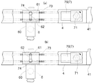
図1に示す集塵フィルタ再生式エアフィルタ装置1(エアフィルタ装置の一例、以下、本装置1という場合がある)は、正面視四角枠状のケーシング2と、ケーシング2の中央開口部に固定される集塵フィルタ3と、ケーシング2の左右両側部に配される昇降ガイドレール(図示せず)に沿って案内される横梁部材4と、横梁部材4を上方向に移動操作する上昇移動用駆動手段5と、集塵フィルタ3に吸込み口を臨ませた状態で左右方向に移動自在に横梁部材4に保持され、集塵フィルタ3に付着した塵埃を吸込み口から吸引除去する吸引ノズル6と、横梁部材4に内設され、吸引ノズル6を左右方向に移動操作する左右移動用駆動手段7と、左右移動用駆動手段7にて吸引ノズル6を左右方向に往復移動させ、且つ、上昇移動用駆動手段5にて横梁部材4を上方向に移動させて塵埃の吸引除去制御を実行させる制御手段H(図示せず)と、を備えて構成されている。
[First Embodiment]
A first embodiment of the present invention will be described with reference to the drawings.
A dust collection filter regenerative
この本装置1においては、吸引ノズル6がフレキシブルホースや配管継手等を介して吸引装置(図示せず)に接続されており、制御手段Hが、この吸引装置を作動させながら上昇移動用駆動手段5及び左右移動用駆動手段7の協働にて吸引ノズル6を上下左右に移動させることにより、集塵フィルタ3に付着した塵埃を集塵フィルタ3の全面に亘って吸引除去(以降、清掃と称することがある)することができるようになっている。
In this
(上下移動のための機構)
図1及び図2に示すように、上昇移動用駆動手段5は、電動機と減速機とが一体的に組み合わされ且つブレーキ機能を備える駆動源としての縦送りモータ50と、ケーシング2の右側部に設けられる昇降移動用チェーン伝動機構10と、ケーシング2の左側部に設けられる昇降移動用チェーン伝動機構10’と、昇降移動用チェーン伝動機構10と10’との間で縦送りモータ50の回転を伝動する左右間チェーン伝動機構9とを備えて構成されている。
(Mechanism for vertical movement)
As shown in FIGS. 1 and 2, the drive means 5 for upward movement includes a
縦送りモータ50は、例えば電磁ブレーキ付の電動機を備えて構成され、後述するように、電動機を作動させることによって横梁部材4を上昇移動させる。また、その電磁ブレーキを作動させることによって横梁部材4を必要な位置に停止させ、横梁部材4の上下方向位置を保持可能に構成されている。さらに、電動機の作動を停止させ且つ電磁ブレーキの作動を停止することによって、横梁部材4の上下方向位置保持を解除し、横梁部材4をその自重により下降移動させることが可能に構成されている。なお、横梁部材4の上下方向位置保持については、電動機への供給電力を調整して電動機のトルクを横梁部材4の自重と釣り合わせることによって実現することも可能である。
The
図1に示すように、昇降移動用チェーン伝動機構10は、縦送りモータ50の回転軸と一体回転する駆動スプロケット51と、その駆動スプロケット51と所定の軸間距離を隔てて下側に配置される従動スプロケット52と、これらスプロケット51,52に無端状に巻き掛けられる昇降用ローラチェーン53とにより構成されている。
As shown in FIG. 1, the
また、左右間チェーン伝動機構9が、縦送りモータ50の回転軸と一体回転するように設けられた主伝動スプロケット91と、その主伝動スプロケット91と所定の軸間距離を隔てて左方に配置される従伝動スプロケット92と、これらスプロケット91,92に無端状に巻き掛けられる伝動用ローラチェーン93とにより構成されている。
Further, the left-right
昇降移動用チェーン伝動機構10’は、左右間チェーン伝動機構9の従伝動スプロケット92の回転軸と一体回転されることによって縦送りモータ50の回転を伝動される駆動スプロケット51’と、その駆動スプロケット51’と所定の軸間距離を隔てて下側に配置される従動スプロケット52’と、これらスプロケット51’,52’に無端状に巻き掛けられる昇降用ローラチェーン53’とにより構成されている。
The chain transmission mechanism 10 'for up-and-down movement is a drive sprocket 51' that is transmitted integrally with the rotation shaft of the driven transmission sprocket 92 of the left-right
横梁部材4の左右両側部には、左右方向に所要長さの長孔42,42’が形成されてなるガイド部材41,41’がそれぞれ固着されている。ガイド部材41,41’は、長孔42,42’に係合する滑車とその滑車を回転自在に支承する支承ピンとから構成される支承機構54,54’を介して、昇降用ローラチェーン53,53’のリンクのうちの1つに連結されている。
図2に昇降移動用チェーン伝動機構10の動作を示す。図示は省略するが、昇降移動用チェーン伝動機構10’の動作も同様である。上昇移動においては、駆動スプロケット51,51’が縦送りモータ50により一方向(図2(a)中の実線矢印方向)に回転駆動され、これにより昇降用ローラチェーン53,53’が一方向に周回運動される。
昇降用ローラチェーン53,53’の周回運動において、支承機構54,54’が駆動スプロケット51,51’又は従動スプロケット52,52’を通過する際には、支承機構54,54’の滑車がガイド部材41,41’の長孔42、42’に沿って左右方向にスライドして支承機構54,54’の進行方向が反転される。
横梁部材4を上昇移動させるときには、上記のように縦送りモータ50を回転駆動することにより、ガイド部材41,41’、及び、そのガイド部材41,41’に固着された横梁部材4は、図2(a)の白抜き矢印の方向に移動されることとなる。
また、横梁部材4を下降移動させるときには、縦送りモータ50の電動機の作動を停止させ且つ電磁ブレーキの作動を停止することによって、横梁部材4の上下方向位置保持を解除する。これにより、横梁部材4は自重により下降移動を行い、図2(b)の白抜き矢印の方向に移動されることとなる。尚、このとき、横梁部材4の下降移動は縦送りモータ50の減速機の作用により急激な移動が制限され、安全な速度でケーシング2の最下部まで下降することとなる。
したがって、横梁部材4は縦送りモータ50の回転駆動により、少なくとも上昇方向に移動可能に構成されている。
FIG. 2 shows the operation of the lifting / lowering
When the
When the
Further, when the
Therefore, the
(左右移動のための機構)
図1に示すように、左右移動用駆動手段7は、電動機と減速機とが一体的に組み合わされてなる駆動源としての横送りモータ70と、横梁部材4に内設されて設けられる左右移動用チェーン伝動機構11とを備えて構成されている。
(Mechanism for lateral movement)
As shown in FIG. 1, the left-right movement drive means 7 includes a
横送りモータ70は、電動機を作動させることによって吸引ノズル6を保持する吸引ノズル保持部60を左右移動させる。また、電動機の作動を停止させることによって吸引ノズル保持部60の移動を停止させるように構成されている。なお、この電動機に、例えば電磁ブレーキ等を設けて吸引ノズル保持部60を停止させるように構成してもよい。
The
左右移動用チェーン伝動機構11は、横送りモータ70の回転軸と一体回転する駆動スプロケット71と、この駆動スプロケット71に対し所定の軸間距離を隔てて左方に配置される従動スプロケット72と、これらスプロケット71、72に無端状に巻き掛けられる左右移動用ローラチェーン73とにより構成されている。
The left-right movement
横梁部材4には、上下方向に所要長さの長孔62が形成されてなるガイド部材61が横梁部材4の長手方向にスライド可能な状態で保持され、その下部には、吸引ノズル6を保持する吸引ノズル保持部60が固着されている。ガイド部材61は、長孔62に係合する滑車とその滑車を回転自在に支承する支承ピンとから構成される支承機構74を介して、左右移動用ローラチェーン73のリンクのうちの1つに連結されている。
吸引ノズル6は、集塵フィルタ3にその吸込み口(本実施形態では円形に形成されているが、その他の形状でもよい)を対向させる状態で設けられている。そして、吸引装置を作動させることによって、その吸込み口が集塵フィルタ3に対向している領域の塵埃を吸引する。したがって、集塵フィルタ3における吸引ノズル6が対向する領域が吸引領域となる。
A
The
図3に示すように、左右移動用駆動手段7においては、駆動スプロケット71が横送りモータ70により一方向(例えば、図3(a)(b)中の実線矢印方向)に回転駆動され、これにより左右移動用ローラチェーン73が一方向に周回運動される。左右移動用ローラチェーン73の周回運動において、支承機構74が駆動スプロケット71又は従動スプロケット72を通過する際には、滑車がガイド部材61の長孔62に沿って上下方向にスライドして支承機構74の進行方向が反転され、ガイド部材61、及び、そのガイド部材61に固着された吸引ノズル保持部60は、図3(a)(b)の白抜き矢印の方向に移動されることとなる。このように、ガイド部材61及び支承機構74は、支承機構74の各支承ピンが駆動スプロケット71及び従動スプロケット72を通過する際に、ノズル保持部60の進行方向を反転させる反転機構として機能する。
したがって、吸引ノズル保持部60に保持される吸引ノズル6は、横送りモータ70の回転駆動により左右方向に移動可能に構成されている。
As shown in FIG. 3, in the lateral movement drive means 7, the
Therefore, the
(吸引除去制御について)
次に、図4に基づいて、制御手段Hによる吸引除去制御の実行について説明する。
この吸引除去制御は、吸引装置を作動させている状態で、上昇移動用駆動手段5および左右移動用駆動手段7の作動状態を制御することによって実現される。以降、この吸引除去制御時には吸引装置を作動させているものとして、上昇移動用駆動手段5および左右移動用駆動手段7の制御に関してのみ説明する。
(About suction removal control)
Next, the execution of the suction removal control by the control means H will be described based on FIG.
This suction removal control is realized by controlling the operating states of the ascending movement driving means 5 and the right and left movement driving means 7 while the suction device is in operation. Hereinafter, only the control of the upward movement drive means 5 and the right and left movement drive means 7 will be described on the assumption that the suction device is operated during the suction removal control.
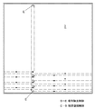
図4において、清掃開始時の吸引ノズル6の位置を開始位置S、終了時の吸引ノズル6の位置を終了位置Eで表す。
清掃の開始が指令され吸引除去制御が開始されると、制御手段Hは、縦送りモータ50により、横梁部材4の上下方向位置を保持させた状態で、左右移動用ローラチェーン73が1周する時間(すなわち、吸引ノズル6が集塵フィルタ3の左右方向で左右端間を一往復する時間)の間、左右移動用駆動手段5を駆動させる。この時間(以降、左右往復時間と称する場合がある)は、吸引ノズル6の左右方向の移動速度、集塵フィルタ3の左右方向の長さ等によって適切に設定され、予め制御手段Hの記憶部(図示せず)に記憶されている。これによって、吸引ノズル6は、横梁部材4に沿って起点S(白丸で表す)から集塵フィルタ3の右端を経て当該起点に戻り、当該起点から左端を経て当該起点(黒丸で表す)に戻るように横梁部材4に沿って左右移動する状態で清掃を実行(以降、左右方向清掃処理と称することがある)し、吸引ノズル6の吸引領域は、上下方向位置が保持された高さ位置において集塵フィルタ3の左右に亘って漏れの無いものとなる。なお、この1回の左右方向移動において、図4中の白丸と黒丸は同一の位置である。
In FIG. 4, the position of the
When the start of cleaning is instructed and the suction removal control is started, the control means H makes one turn of the lateral
その後、制御手段Hは、縦送りモータ50を駆動させることによって、横梁部材4を上昇移動させる制御を実行する(図4中の黒丸の位置から白丸の位置への上昇移動)。この上昇移動距離(図4中の黒丸の位置から白丸の位置への移動距離)は、吸引ノズル6の吸引領域の上下方向距離よりも短く設定されている。例えば、上昇移動距離は、吸引領域の上下方向距離の半分に設定されている。この上昇移動距離を移動するための制御時間(以降、上昇移動時間と称する場合がある)は、吸引ノズル6の上方向の移動速度、吸引ノズル6の吸引領域の上下方向の長さ等によって適切に設定され、予め制御手段Hの記憶部(図示せず)に記憶されている。これによって、上昇移動前の吸引ノズル6の吸引領域と上昇移動後の吸引ノズル6の吸引領域とに重複する領域を有する状態となり、横梁部材4の上昇移動前の吸引領域と横梁部材4の上昇移動後の吸引領域との間に漏れの無いものとなる。
Thereafter, the control means H executes a control for moving the
次に、制御手段Hは、縦送りモータ50により、その上昇移動後の横梁部材4の上下方向位置を保持させた状態で、左右往復時間の間、左右移動用駆動手段5を駆動させて再度左右方向清掃処理を実行する。そして、この左右方向清掃処理と上昇移動とを、吸引ノズル6が集塵フィルタ3の最下部から最上部に達するまで繰り返す。したがって、集塵フィルタの最下部から最上部までにおける左端から右端に亘って、ほとんど漏れのない状態で確実に清掃を行うことができるものとなる。
Next, the control means H drives the right and left movement drive means 5 for the left and right reciprocation time in a state where the vertical position of the
制御手段Hは、集塵フィルタ3の左右方向の長さと上下方向の長さ、並びに、吸引ノズルの左右方向の長さと上下方向の長さとその移動速度等によって規定される、左右方向清掃処理と上昇移動とを集塵フィルタ3の最下部から最上部まで行うために必要な時間、すなわち、左右往復時間を左右方向清掃処理を繰り返す回数倍した時間と、上昇移動時間を上昇移動する回数倍した時間との和の時間を、清掃に要する清掃完了時間として記憶している。つまり、この清掃完了時間が単位クリーニングの時間となる。
The control means H includes a horizontal cleaning process defined by the length of the
そして、前記清掃完了時間の間、左右移動用駆動手段5の駆動によって吸引ノズル6を左右方向に移動させて左右方向清掃処理を実行した後、上昇移動用駆動手段7の駆動によって吸引ノズル6を上昇移動させる動作を繰り返すことにより、吸引ノズル6を集塵フィルタ3の最下部から最上部(図4においてS→Eで示す)まで移動させて清掃を行う吸引除去制御を実行する。
Then, during the cleaning completion time, the
(横梁復帰制御について)
制御手段Hは、上記のように、吸引ノズル6の左右移動及び横梁部材4の上昇移動に伴って塵埃の吸引除去を実行する吸引除去制御を実行した後、すなわち、吸引除去制御の開始から清掃完了時間が経過して、吸引ノズル6が最上部まで清掃を完了したものと判断すると、横梁復帰制御を行う。この横梁復帰制御は、縦送りモータ50の電磁ブレーキを解除することによって横梁部材4の上下方向位置保持を解除して、横梁部材4をケーシング2の最下部に移動させる制御である。このとき、横梁部材4はその自重により下降移動を行う。尚、このとき、横梁部材4の下降移動は縦送りモータ50の減速機の作用により急激な移動が制限され、安全な速度でケーシング2の最下部まで下降することとなる。
このようにして、吸引ノズル6が終了位置Eに到達したとき、つまり清掃が完了したときには、横梁復帰制御を実行することによって、吸引ノズル6を開始位置Sに復帰させる(図4においてE→Sで示す)ことができる。
したがって、清掃が終了する毎に、横梁部材4はケーシング2の最下部まで移動され、吸引ノズル6は次回の清掃開始までケーシング2の最下部、つまり、集塵フィルタ3の最下部にて待機する状態となる。これによって、次回の清掃においては、常に集塵フィルタ3の最下部から吸引ノズル6の上昇移動を開始させることとなるので、清掃完了時間だけ吸引ノズル6による清掃を実行することにより、集塵フィルタの全面を漏れなく清掃することができるものとなる。
(About transverse beam return control)
As described above, the control means H performs the cleaning after the suction removal control for performing the suction removal of the dust along with the left-right movement of the
Thus, when the
Therefore, every time cleaning is completed, the
すなわち、従来の構成においては集塵フィルタ103の全面を漏れなく清掃するために、吸引ノズルを集塵フィルタ103の左右方向に往復分の距離で、且つ、上下方向に往復分の距離を移動操作させる時間、すなわち最小時間の4倍の時間が必要であったのに対して、本実施形態においては、吸引ノズル6を集塵フィルタ3の左右方向に往復分の距離で、且つ、上下方向に片道分の距離を移動操作させる時間、つまり、上記従来の1/2の時間(最小時間の2倍の時間)で集塵フィルタ3の全面を漏れなく清掃することができるものとなる。
また、従来の構成における、吸引ノズルを集塵フィルタ103の左右方向に片道分の距離で、且つ、上下方向に往復分の距離を移動操作させる構成と比較すると、本実施形態はその時間としては等しいものであるが、従来の構成においては集塵フィルタ103の全面を清掃できない(例えば、左右方向でクリーニングされていない部分が残る)虞があるのに対して、本実施形態では集塵フィルタの左右方向及び上下方向における全面を漏れなく清掃することができるものとなる。
That is, in the conventional configuration, in order to clean the entire surface of the
Compared with the configuration in which the suction nozzle is operated to move the distance of one way in the left-right direction of the
〔第2実施形態〕
次に本発明の第2実施形態について説明する。
この第2実施形態は、上昇移動用駆動手段5のうちの一方(本実施形態では左側)の昇降移動用チェーン伝動機構10’及び左右間チェーン伝動機構9を省略し、その代わりに、上昇移動用駆動手段5による横梁部材4の上下駆動と釣り合いをとるカウンターウェイト機構12が設けられている点で第1実施形態と異なる他は、第1実施形態と同一の構成であり、この同一の構成については説明を省略する。
図5に示すように、このカウンターウェイト機構12は、一端が横梁部材4の左側部に固着され、他端に錘体57が固着されたカウンターウェイトチェーン58と、ケーシング2の上部に回転自在に固定され、カウンターウェイトチェーン57が巻き掛けられたスプロケット56とから構成されている。
[Second Embodiment]
Next, a second embodiment of the present invention will be described.
In the second embodiment, one of the ascending movement driving means 5 (left side in the present embodiment) is not provided with the lifting / lowering chain transmission mechanism 10 'and the left-right
As shown in FIG. 5, the
そして、吸引除去制御において、横梁部材4の一端側に固着された上昇移動用駆動手段5が横梁部材4を上昇移動させるときには、横梁部材4の他端側に係合されたカウンターウェイト機構12が、上昇移動用駆動手段5による横梁部材4の上昇移動に伴って錘体57を下降させることにより、横梁部材4の重心を所定の位置に収めるべく釣り合いをとるものとなる。
又、横梁復帰制御が実行されて横梁部材4をその自重により下降させるときには、カウンターウェイト機構12が、横梁部材4の下降移動に伴って錘体57を上昇させることにより、横梁部材4の重心を所定の位置に収めるべく釣り合いをとるものとなる。
したがって、昇降移動用チェーン伝動機構10’及び左右間チェーン伝動機構9を省略した簡易な構成としながらも、横梁部材を安定して上下移動させることができることとなる。
In the suction removal control, when the ascending movement driving means 5 fixed to one end side of the
Further, when the transverse beam return control is executed and the
Therefore, the horizontal beam member can be stably moved up and down while having a simple configuration in which the lifting / lowering
〔別実施形態〕
(イ)上記第1及び第2実施形態では、縦送りモータ50により横梁部材4の上下方向位置を保持させた状態で、左右移動用ローラチェーン73が1周する時間、すなわち、吸引ノズル6が集塵フィルタ3の左右端間を一往復する時間の間、左右移動用駆動手段5を駆動させるように構成していたが、この構成に限定されるものではない。例えば左右移動用ローラチェーン73が1周する時間の半分、すなわち、吸引ノズル6が集塵フィルタ3の左右方向で左右端間を片道分の距離だけ移動する時間の間、左右移動用駆動手段5を駆動させるように構成してもよい。
このように構成した場合、吸引ノズル6が左右方向を移動する時間は、集塵フィルタ3の左右方向において片道分の時間となり、清掃完了時間は上記第1及び第2実施形態の1/2となる。
この清掃完了時間は従来の構成における最小時間と等しいものであるが、従来の構成においては集塵フィルタ103の上下方向について清掃されていない部分が残る虞があるものとなるのに対して、本別実施形態では集塵フィルタ3の上下方向については最下部から最上部まで漏れのない状態で清掃できるものとなる。
[Another embodiment]
(A) In the first and second embodiments described above, when the
In such a configuration, the time for the
This cleaning completion time is equal to the minimum time in the conventional configuration. However, in the conventional configuration, there is a possibility that an uncleaned portion in the vertical direction of the
(ロ)上記第1実施形態では、上昇移動用駆動手段5が、少なくとも縦送りモータ50と、その縦送りモータ50にて循環駆動される昇降用ローラチェーン53,53’とを備えて構成される構成としたが、このような構成に限定されるものではない。すなわち、本発明において、横梁部材4の上下方向への移動は、吸引除去処理を実行する間ケーシング2の最下部から最上部まで上昇方向に移動させ、清掃完了時間経過後には、ケーシング2の最上部からは自重にて下方移動をさせることができればよいのであり、例えば、縦送りモータにて回転駆動される巻き上げドラムと、一端が横梁部材4に固着され且つ他端が前記巻き上げドラムに巻き付けられる状態に固定されるワイヤロープとによって構成される巻上機(ウィンチ)によって上昇移動させる構成とすることも可能である。
(B) In the first embodiment, the ascending movement driving means 5 includes at least the
(ハ)上記第1及び第2実施形態では、電動機と減速機とブレーキとが一体的に組み合わされてなる駆動源としての縦送りモータ50を用いる構成としたが、電動機と減速機とブレーキとは別体として構成されるものでもよい。ただし、このとき、それら駆動力或いは制動力を伝達する部材夫々の間は、塵埃が付着しないように構成すること(たとえばこれら電動機と減速機とブレーキとをケーシング内に収容する等)が望ましい。
なお、上記ブレーキとしては、モータの回転を停止させた上で、ブレーキパッドにより機械的にモータの回転軸を停止させる、或いは、係止ピンにてケーシング2に対して横位置を固定する等して機械的に停止させる構成を採用することも可能である。
(C) In the first and second embodiments, the
As the brake, the rotation of the motor is stopped and the rotation shaft of the motor is mechanically stopped by a brake pad, or the lateral position is fixed to the
(ニ)上記第1及び第2実施形態では、横梁復帰制御として、上昇移動用駆動手段5による横梁部材4の上下方向位置保持を解除して、横梁部材4をその自重によりケーシング2の最下部に移動させる構成としたが、このような構成に限定されるものではない。例えば、上記別実施形態(ロ)のように巻上機を使用する構成とした場合、巻き上げドラムを回転させる縦送りモータを逆回転させることによって、横梁部材4をケーシング2の最下部に移動させることも可能である。また、巻き上げドラムの回転制止を解除して、第1及び第2実施形態同様に横梁部材4をその自重によって下方移動させることも可能である。
(D) In the first and second embodiments, as the transverse beam return control, the vertical position holding of the
(ホ)上記第1及び第2実施形態では、吸引ノズル6を起点から集塵フィルタ3の右端を経て当該起点に戻り、当該起点から左端を経て当該起点に戻るように横梁部材4に沿って左右移動するように構成したが、集塵フィルタ3の左端を経て当該起点に戻り、当該起点から右端を経て当該起点に戻るように構成してもよく、また、上昇移動前の吸引ノズル6の吸引領域の上端と上昇移動後の吸引ノズル6の吸引領域の下端とが同一の位置になるように構成することも可能である。
(E) In the first and second embodiments, the
(ヘ)上記第1及び第2実施形態では、縦送りモータ50に、電磁ブレーキ付の電動機を備える構成としたが、このような電磁ブレーキ付の電動機に代えてステッピングモータを用いることも可能である。この場合には、横梁部材4を上下方向位置保持させるときには励磁状態を保持しておき、上下方向位置保持を解除して横梁部材4を下降させるときには、供給する電流を停止し、励磁状態を解除するように構成することができる。また、このステッピングモータに回生制動機能が付随している場合には、回生制動力にて横梁部材4の下方移動を制限するように構成することも可能である。
(F) In the first and second embodiments, the
(ト)上記第1実施形態では、昇降移動用チェーン伝動機構10および10’の昇降用ローラチェーン53,53’が、また、上記第2実施形態では昇降移動用チェーン伝動機構10の昇降用ローラチェーン53が、一方向に周回運動されるように構成した。しかしながら、このような構成に限定されるものではなく、例えば、横梁部材4が集塵フィルタ3の最上部に達するまで上昇移動した後、横梁復帰制御を実行する際には、一方向に周回運動していた昇降用ローラチェーン53と53’、又は昇降用ローラチェーン53を、逆方向に周回運動するようにしてもよい。また、このような構成とする場合には、昇降用ローラチェーン53と53’とは周回運動をせず、吸引除去制御において縦送りモータ50にて横梁部材4を集塵フィルタ3の最下部から最上部まで上昇移動させる状態と、横梁復帰制御において横梁部材4の自重で横梁部材4が集塵フィルタ3の最上部から最下部まで下降移動する状態との間で、昇降用ローラチェーン53,53’が往復運動のみをするように構成することも可能である。
(G) In the first embodiment, the lifting
(チ)上記第2実施形態では、カウンターウェイト機構12としてカウンターウェイトチェーン58とスプロケット56を用いる構成としたが、このような構成に限定されるものではなく、例えば、カウンターウェイトチェーン58に代えてワイヤロープ等を使用し、スプロケット56に代えてケーシング2の上部に回転自在に固定したプーリを備え、このプーリにワイヤロープ等を巻き掛けるように構成することも可能である。
(H) In the second embodiment, the
本発明は、装置を信頼性の高いものとするとともに、合理的で無駄のないクリーニングを自動的に行えるエアフィルタ装置として有用に利用可能である。 INDUSTRIAL APPLICABILITY The present invention can be usefully used as an air filter device that makes a device highly reliable and can automatically perform rational and wasteless cleaning.
1 集塵フィルタ再生式エアフィルタ装置(エアフィルタ装置)
2 ケーシング
3 集塵フィルタ
4 横梁部材
5 上昇移動用駆動手段
6 吸引ノズル
7 左右移動用駆動手段
9 左右間チェーン伝動機構(上昇移動用駆動手段)
10,10’ 昇降移動用チェーン伝動機構(上昇移動用駆動手段)
11 左右移動用チェーン伝動機構(左右移動用駆動手段)
12 カウンターウェイト機構
50 縦送りモータ(上昇移動用駆動手段)
53,53’ 昇降用ローラチェーン
70 横送りモータ(左右移動用駆動手段)
73 左右移動用ローラチェーン
1 Dust collection filter regenerative type air filter device (air filter device)
2
10, 10 'Elevating and moving chain transmission mechanism (rising and moving drive means)
11 Left-right movement chain transmission mechanism (left-right movement drive means)
12
53, 53 'Elevating
73 Roller chain for lateral movement
Claims (5)
前記吸引ノズルを左右方向に移動自在に保持し且つ前記ケーシングの上下方向に移動自在に保持される横梁部材と、
前記吸引ノズルを左右方向に移動操作する左右移動用駆動手段と、
前記横梁部材を上方向に移動操作する上昇移動用駆動手段と、
前記左右移動用駆動手段にて前記吸引ノズルを左右方向に往復移動させ、且つ、前記上昇移動用駆動手段にて前記横梁部材を上方向に移動させて前記塵埃の吸引除去を実行させる制御手段とが設けられ、
前記制御手段が、
前記吸引ノズルの左右移動及び前記横梁部材の上昇移動に伴って前記塵埃の吸引除去を実行する吸引除去制御を実行した後、前記上昇移動用駆動手段による前記横梁部材の上下方向位置保持を解除して、前記横梁部材を前記ケーシングの最下部に移動させる横梁復帰制御を実行するエアフィルタ装置。 A suction nozzle for sucking and removing dust adhering to the dust collecting filter fixed to the casing from the suction port;
A transverse beam member that holds the suction nozzle movably in the left-right direction and is held movably in the up-down direction of the casing;
A drive means for moving left and right to move the suction nozzle in the left and right direction;
Driving means for moving up to move the cross beam member upward;
Control means for causing the suction nozzle to reciprocate in the left-right direction by the right-and-left movement drive means, and moving the cross beam member upward by the ascending-movement drive means to perform suction removal of the dust. Is provided,
The control means is
After performing suction removal control for performing suction removal of the dust in accordance with the lateral movement of the suction nozzle and the upward movement of the horizontal beam member, the vertical position holding of the horizontal beam member by the upward movement driving means is released. An air filter device that executes transverse beam return control for moving the transverse beam member to the lowermost part of the casing.
Priority Applications (1)
| Application Number | Priority Date | Filing Date | Title |
|---|---|---|---|
| JP2009050691A JP2010201364A (en) | 2009-03-04 | 2009-03-04 | Air filter |
Applications Claiming Priority (1)
| Application Number | Priority Date | Filing Date | Title |
|---|---|---|---|
| JP2009050691A JP2010201364A (en) | 2009-03-04 | 2009-03-04 | Air filter |
Publications (1)
| Publication Number | Publication Date |
|---|---|
| JP2010201364A true JP2010201364A (en) | 2010-09-16 |
Family
ID=42963400
Family Applications (1)
| Application Number | Title | Priority Date | Filing Date |
|---|---|---|---|
| JP2009050691A Pending JP2010201364A (en) | 2009-03-04 | 2009-03-04 | Air filter |
Country Status (1)
| Country | Link |
|---|---|
| JP (1) | JP2010201364A (en) |
Cited By (2)
| Publication number | Priority date | Publication date | Assignee | Title |
|---|---|---|---|---|
| JP2016068000A (en) * | 2014-09-29 | 2016-05-09 | 日本バイリーン株式会社 | Filter device |
| CN114797308A (en) * | 2022-04-08 | 2022-07-29 | 中冶节能环保有限责任公司 | Straight-through type intelligent bag type dust removal system |
Citations (10)
| Publication number | Priority date | Publication date | Assignee | Title |
|---|---|---|---|---|
| JPS4864870U (en) * | 1971-11-18 | 1973-08-17 | ||
| JPH0595620U (en) * | 1992-05-29 | 1993-12-27 | 日本エアー・フィルター株式会社 | Air filter media regenerator fixed position stop device |
| JP3021210U (en) * | 1995-08-01 | 1996-02-20 | 寉也 上島 | Filter media regeneration type air filter device |
| JP3026240U (en) * | 1995-12-22 | 1996-07-02 | 寉也 上島 | Filter media regenerative air filter drive |
| JP2006132903A (en) * | 2004-11-09 | 2006-05-25 | Matsushita Electric Ind Co Ltd | Air conditioner with indoor unit with automatic air filter cleaning function |
| JP2007101101A (en) * | 2005-10-06 | 2007-04-19 | Matsushita Electric Ind Co Ltd | Air conditioner |
| JP2007271170A (en) * | 2006-03-31 | 2007-10-18 | Fujitsu General Ltd | Air conditioner |
| JP2008261455A (en) * | 2007-04-13 | 2008-10-30 | Nippon Spindle Mfg Co Ltd | Chain tensioner |
| JP2009002602A (en) * | 2007-06-22 | 2009-01-08 | Panasonic Corp | Air conditioner |
| JP2009030855A (en) * | 2007-07-26 | 2009-02-12 | Panasonic Corp | Air conditioner |
-
2009
- 2009-03-04 JP JP2009050691A patent/JP2010201364A/en active Pending
Patent Citations (10)
| Publication number | Priority date | Publication date | Assignee | Title |
|---|---|---|---|---|
| JPS4864870U (en) * | 1971-11-18 | 1973-08-17 | ||
| JPH0595620U (en) * | 1992-05-29 | 1993-12-27 | 日本エアー・フィルター株式会社 | Air filter media regenerator fixed position stop device |
| JP3021210U (en) * | 1995-08-01 | 1996-02-20 | 寉也 上島 | Filter media regeneration type air filter device |
| JP3026240U (en) * | 1995-12-22 | 1996-07-02 | 寉也 上島 | Filter media regenerative air filter drive |
| JP2006132903A (en) * | 2004-11-09 | 2006-05-25 | Matsushita Electric Ind Co Ltd | Air conditioner with indoor unit with automatic air filter cleaning function |
| JP2007101101A (en) * | 2005-10-06 | 2007-04-19 | Matsushita Electric Ind Co Ltd | Air conditioner |
| JP2007271170A (en) * | 2006-03-31 | 2007-10-18 | Fujitsu General Ltd | Air conditioner |
| JP2008261455A (en) * | 2007-04-13 | 2008-10-30 | Nippon Spindle Mfg Co Ltd | Chain tensioner |
| JP2009002602A (en) * | 2007-06-22 | 2009-01-08 | Panasonic Corp | Air conditioner |
| JP2009030855A (en) * | 2007-07-26 | 2009-02-12 | Panasonic Corp | Air conditioner |
Cited By (3)
| Publication number | Priority date | Publication date | Assignee | Title |
|---|---|---|---|---|
| JP2016068000A (en) * | 2014-09-29 | 2016-05-09 | 日本バイリーン株式会社 | Filter device |
| CN114797308A (en) * | 2022-04-08 | 2022-07-29 | 中冶节能环保有限责任公司 | Straight-through type intelligent bag type dust removal system |
| CN114797308B (en) * | 2022-04-08 | 2023-06-09 | 中冶节能环保有限责任公司 | Straight-through intelligent bag type dust removing system |
Similar Documents
| Publication | Publication Date | Title |
|---|---|---|
| US8127390B2 (en) | Robot for cleaning wall/window | |
| CN109159265A (en) | A kind of napper for precast concrete | |
| CN101056806A (en) | Conveying mechanism cleaning device and method | |
| JP2010201364A (en) | Air filter | |
| CN107504510A (en) | A special-shaped climbing chimney cleaning robot and its cleaning method | |
| CN108995730B (en) | Magnetic adsorption type transverse obstacle-surmounting wall-climbing robot | |
| JP6464405B2 (en) | Filter device | |
| JP6337796B2 (en) | Man conveyor | |
| KR101295597B1 (en) | Apparatus for removing fallen ore of belt conveyor | |
| CN108340154B (en) | Scraper chain automatic assembly device and assembly method | |
| CN209551701U (en) | A kind of cantilevered manipulator | |
| JP6141461B2 (en) | Elevator apparatus and repair method thereof | |
| KR20140003176U (en) | over head crane structure providing cleaning function of surface plate | |
| JP2015009976A (en) | Elevator glass window cleaning device | |
| CN1744846A (en) | Wet-wiping device | |
| KR100742830B1 (en) | Double sided conveyor for conveying strips | |
| JP6152963B2 (en) | Elevator, elevator additional connecting device, and elevator repair method | |
| CN210830359U (en) | Transmission device for slag scraping machine and slag scraping machine with same | |
| JP5501989B2 (en) | Oil pan cleaning control device for passenger conveyor, oil pan cleaning method for passenger conveyor | |
| CN114590592A (en) | Double-platform warping degree detection mechanism | |
| JP2012062167A (en) | Cleaning method of escalator and cleaning device used therefor | |
| JP2005231837A (en) | Manual rotation drive device for elevator hoisting machine and manual rotation drive method for elevator hoisting machine | |
| CN109318029B (en) | A straight steel bar on-line device | |
| CN112061521B (en) | A fully automatic vibration smoothing transmission equipment | |
| KR102869659B1 (en) | Drive chain replacement jig |
Legal Events
| Date | Code | Title | Description |
|---|---|---|---|
| A625 | Written request for application examination (by other person) |
Free format text: JAPANESE INTERMEDIATE CODE: A625 Effective date: 20110801 |
|
| A977 | Report on retrieval |
Free format text: JAPANESE INTERMEDIATE CODE: A971007 Effective date: 20120607 |
|
| A131 | Notification of reasons for refusal |
Free format text: JAPANESE INTERMEDIATE CODE: A131 Effective date: 20120621 |
|
| A02 | Decision of refusal |
Free format text: JAPANESE INTERMEDIATE CODE: A02 Effective date: 20130207 |