JP2010201980A - Airbag and airbag device - Google Patents
Airbag and airbag device Download PDFInfo
- Publication number
- JP2010201980A JP2010201980A JP2009047168A JP2009047168A JP2010201980A JP 2010201980 A JP2010201980 A JP 2010201980A JP 2009047168 A JP2009047168 A JP 2009047168A JP 2009047168 A JP2009047168 A JP 2009047168A JP 2010201980 A JP2010201980 A JP 2010201980A
- Authority
- JP
- Japan
- Prior art keywords
- airbag
- bag
- occupant
- center bag
- head
- Prior art date
- Legal status (The legal status is an assumption and is not a legal conclusion. Google has not performed a legal analysis and makes no representation as to the accuracy of the status listed.)
- Granted
Links
Images


Landscapes
- Air Bags (AREA)
Abstract
【課題】助手席乗員用のエアバッグの展開特性を容易に向上する。
【解決手段】インストルメントパネル部から展開する助手席乗員用のエアバッグ11は、センタバッグ21と、このセンタバッグ21の両側部に連結された一対のサイドバッグ22とを備える。センタバッグ21は、乗員Aの頭部A1に対向する頭部保護部24を備える。サイドバッグ22は、乗員Aの肩部A2に対向する肩部保護部34とを備える。センタバッグ21の基部30からガスを供給し、連通部32,42を介してセンタバッグ21からサイドバッグ22にガスを供給する。乗員Aの頭部A1及び両側の肩部A2を拘束する3個の互いに独立した袋体を備えるため、乗員Aの頭部A1と肩部A2とにそれぞれ好ましい特性でエアバッグ11を展開することが容易になる。
【選択図】図1A deployment characteristic of an airbag for a passenger in a passenger seat is easily improved.
An airbag 11 for a passenger on a passenger seat that is deployed from an instrument panel includes a center bag 21 and a pair of side bags 22 connected to both sides of the center bag 21. The center bag 21 includes a head protecting portion 24 that faces the head A1 of the occupant A. The side bag 22 includes a shoulder protection portion 34 that faces the shoulder A2 of the occupant A. Gas is supplied from the base 30 of the center bag 21, and gas is supplied from the center bag 21 to the side bag 22 via the communication portions 32 and 42. The airbag 11 is deployed on the head A1 and the shoulder A2 of the occupant A with favorable characteristics, respectively, since the bag A includes three independent bags that restrain the head A1 and the shoulders A2 on both sides of the occupant A. Becomes easier.
[Selection] Figure 1
Description
本発明は、例えば、自動車のインストルメントパネル部に備えられる助手席乗員用のエアバッグ及びエアバッグ装置に関する。 The present invention relates to an airbag and an airbag device for a passenger on a passenger seat provided in an instrument panel portion of an automobile, for example.
従来、例えば、自動車のインストルメントパネル部に備えられる助手席乗員用のエアバッグ装置が知られている。このエアバッグ装置は、インストルメントパネル部にケース体を備え、このケース体の内側に、ガスを供給するインフレータと、所定の形状に折り畳まれた袋状のエアバッグとを収納している。そして、自動車の衝突などの際には、インフレータからガスを供給して、助手席に着席した乗員の前方にエアバッグを膨張展開させ、乗員を拘束して乗員に加わる衝撃を緩和するようになっている。 DESCRIPTION OF RELATED ART Conventionally, the airbag apparatus for passenger seat passenger | crew with which the instrument panel part of a motor vehicle is equipped is known, for example. This airbag device includes a case body in an instrument panel portion, and stores an inflator for supplying gas and a bag-like airbag folded into a predetermined shape inside the case body. In the event of a car collision, etc., gas is supplied from the inflator to inflate and deploy the airbag in front of the passenger seated in the passenger seat, restraining the passenger and reducing the impact applied to the passenger. ing.
そして、このようなエアバッグについて、エアバッグの低容量化を図り、エアバッグの内側を種々の構成の仕切り材で仕切った構成が知られている(例えば、特許文献1参照)。しかしながら、この構成では、エアバッグの外殻は1個の袋体であり、エアバッグの幅方向の中央部分は上下に連続するため、乗員の頭部と腹部とに同じ内圧のエアバッグが対向し、かつ、ほぼ同時に拘束する。そこで、乗員の頭部と腹部とに対しそれぞれ好ましい特性を実現する設定は容易ではない。 And about such an airbag, the structure which reduced the capacity | capacitance of an airbag and partitioned the inside of the airbag with the partition material of various structures is known (for example, refer patent document 1). However, in this configuration, the outer shell of the airbag is a single bag body, and since the central portion in the width direction of the airbag continues up and down, the airbag of the same internal pressure faces the occupant's head and abdomen. And restrained almost simultaneously. Therefore, it is not easy to set a desired characteristic for the occupant's head and abdomen.
また、例えば、乗員の肩を拘束する両側の肩拘束部の間に、乗員の頭部に正対する頭部拘束面部を設けた構成が知られている(例えば、特許文献2参照)。しかしながら、この構成においては、エアバッグの外殻は1個の袋体であるとともに、エアバッグの内部は1個の気室であり、頭部と肩部とに対しそれぞれ好ましい特性を実現する設定は容易ではないとともに、エアバッグの形状が複雑になり、製造コストの低減が容易でない。 Further, for example, a configuration is known in which a head restraint surface portion facing the occupant's head is provided between the shoulder restraint portions on both sides that restrain the occupant's shoulder (see, for example, Patent Document 2). However, in this configuration, the outer shell of the airbag is a single bag body, and the interior of the airbag is a single air chamber, which is set to achieve favorable characteristics for the head and shoulders, respectively. Is not easy, and the shape of the airbag is complicated, and it is not easy to reduce the manufacturing cost.
上記のように、従来の構成では、頭部と肩部とをそれぞれ好ましい特性で拘束することが容易でない問題を有している。 As described above, the conventional configuration has a problem that it is not easy to restrain the head and the shoulder with preferable characteristics.
本発明は、このような点に鑑みなされたもので、乗員の頭部と肩部とを容易に好ましい特性で拘束して保護できるエアバッグ及びエアバッグ装置を提供することを目的とする。 The present invention has been made in view of these points, and an object of the present invention is to provide an airbag and an airbag apparatus that can easily restrain and protect an occupant's head and shoulders with preferable characteristics.
請求項1記載のエアバッグは、ガスが流入して乗員の上半身に対向して膨張展開するエアバッグであって、前記乗員の頭部に対向する頭部保護部を設けた袋状のセンタバッグと、それぞれ前記乗員の肩部に対向する肩部保護部を設け前記センタバッグの両側部に連結されかつ前記センタバックとは独立した袋状をなす一対のサイドバッグとを具備したものである。 The airbag according to claim 1 is an airbag that inflates and deploys against the upper body of an occupant when gas flows in, and is a bag-shaped center bag provided with a head protection portion facing the occupant's head. And a pair of side bags which are provided with shoulder protection portions facing the shoulder portions of the occupant and are connected to both side portions of the center bag and form a bag shape independent of the center bag.
請求項2記載のエアバッグは、請求項1記載のエアバッグにおいて、センタバッグと両側のサイドバッグとをそれぞれ連通する連通部と、前記センタバッグに設けられガスが導入されるとともに被取付部材に取り付けられる基部とを具備したものである。 The airbag according to claim 2 is the airbag according to claim 1, wherein the center bag and the side bags on both sides communicate with each other, the center bag is provided with gas, and is attached to the attached member. And a base to be attached.
請求項3記載のエアバッグは、請求項1または2記載のエアバッグにおいて、エアバッグが膨張展開した状態で、肩部保護部は頭部保護部よりも乗員側に位置するものである。 The airbag according to claim 3 is the airbag according to claim 1 or 2, wherein the shoulder protection portion is positioned closer to the occupant side than the head protection portion in a state where the airbag is inflated and deployed.
請求項4記載のエアバッグ装置は、車両のインストルメントパネル部に設置されるエアバッグ装置であって、請求項1ないし3いずれか一記載のエアバッグと、このエアバッグにガスを供給するインフレ−タとを具備し、前記エアバッグは、着席した乗員の上半身の正面側に対向して膨張展開し、センタバッグは、前記インストルメントパネル部の上面部に取り付けられ、サイドバッグは、少なくとも一部が前記センタバッグより下方に膨張展開し、前記インストルメントパネル部の正面部と乗員との間に膨張展開するものである。 An airbag device according to claim 4 is an airbag device installed in an instrument panel portion of a vehicle, and the airbag according to any one of claims 1 to 3 and an inflation for supplying gas to the airbag. The airbag is inflated and deployed facing the front side of the upper body of a seated occupant, the center bag is attached to the upper surface of the instrument panel, and the side bag is at least one The portion is inflated and deployed below the center bag, and inflated and deployed between the front portion of the instrument panel portion and the occupant.
請求項1記載のエアバッグによれば、頭部及び両側の肩部を拘束する3個の互いに独立した袋体であるセンタバッグとサイドバッグとを備えたため、これらセンタバッグ及びサイドバッグの展開位置及び反力を容易に異なる所望の値に調整でき、頭部及び肩部に対してそれぞれ好ましい特性を容易に実現して保護できる。また、両側の肩部を拘束することにより、乗員の体全体の移動を十分に抑えて保護できるとともに、胸部を拘束せず、エアバッグから胸部へ加わる力を抑制ないしなくすことができる。センタバッグとサイドバッグとの構造は簡略化でき、製造コストを低減できる。 According to the airbag of the first aspect, since the center bag and the side bag, which are three independent bag bodies that restrain the head portion and the shoulder portions on both sides, are provided, the deployment positions of the center bag and the side bag are provided. And the reaction force can be easily adjusted to different desired values, and preferable characteristics can be easily realized and protected for the head and shoulder, respectively. Further, by restraining the shoulders on both sides, the movement of the entire body of the occupant can be sufficiently suppressed and protected, and the force applied from the airbag to the chest can be suppressed or eliminated without restraining the chest. The structure of the center bag and the side bag can be simplified, and the manufacturing cost can be reduced.
請求項2記載のエアバッグによれば、請求項1記載の効果に加え、センタバッグにガスを供給することにより、センタバッグから連通部を介してサイドバッグにガスが供給される。展開初期には、センタバッグを十分に膨張展開させ、完全展開時には、センタバッグの反力を小さくするとの特性を容易に実現できる。 According to the airbag of the second aspect, in addition to the effect of the first aspect, by supplying the gas to the center bag, the gas is supplied from the center bag to the side bag through the communication portion. The characteristic that the center bag is sufficiently inflated and deployed at the initial stage of deployment and the reaction force of the center bag is reduced at the time of complete deployment can be easily realized.
請求項3記載のエアバッグによれば、請求項1または2記載の効果に加え、頭部保護部よりも乗員側に位置する肩部保護部で乗員を十分に拘束して乗員を保護できる。センタバッグとサイドバッグとは別体であるため、肩部保護部と頭部保護部との位置の調整を容易に実現できる。 According to the airbag of the third aspect, in addition to the effect of the first or second aspect, the occupant can be sufficiently restrained by the shoulder protection part positioned on the occupant side relative to the head protection part to protect the occupant. Since the center bag and the side bag are separate bodies, adjustment of the positions of the shoulder protection part and the head protection part can be easily realized.
請求項4記載のエアバッグ装置によれば、請求項1ないし3いずれか一記載のエアバッグを備えたため、それぞれの効果を奏するとともに、インストルメントパネル部の上面部に取り付けられるセンタバッグに対し、サイドバッグは、少なくとも一部がセンタバッグより下方に膨張展開してインストルメントパネル部の正面部と乗員との間に膨張展開するため、少ない容量で乗員の肩部を安定して拘束できる。 According to the airbag device of the fourth aspect, since the airbag according to any one of the first to third aspects is provided, the center bag attached to the upper surface portion of the instrument panel portion has the respective effects, Since at least a part of the side bag is inflated and deployed below the center bag and inflated and deployed between the front portion of the instrument panel and the occupant, the shoulder portion of the occupant can be stably restrained with a small capacity.
以下、本発明のエアバッグ及びエアバッグ装置の一実施の形態を図面を参照して説明する。 Hereinafter, an embodiment of an airbag and an airbag device of the present invention will be described with reference to the drawings.
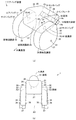
図1及び図2において、1はエアバッグ装置で、このエアバッグ装置1は、移動体である車両としての自動車2の助手席、すなわち被保護物である助手席の乗員Aの前方に位置する被設置部としてのインストルメントパネル部4の内側に配置され、アシストエアバッグなどとも呼ばれる助手席乗員用のエアバッグ装置1を構成している。なお、以下、前後方向、両側方向、及び上下方向は、それぞれエアバッグ装置1を自動車2に取り付けた状態における自動車2の直進方向を基準として説明し、エアバッグ装置1から見て、後側である正面側が乗員側Bとなる。そして、インストルメントパネル部4は、後側すなわち助手席側に向かって若干下降する曲面状などに形成され、上側に臨む上面部4aと、乗員側Bに臨む正面部4bとを備えている。そして、エアバッグ装置1は、インストルメントパネル部4の上面部4aに埋め込むようにして設置され、このインストルメントパネル部4の内側に配置された図示しないステアリングメンバに、エアバッグ装置1が正面側を上方から若干後側すなわち乗員A側に向けて傾斜した状態でねじ止めなどして固定されている。また、インストルメントパネル部4の上方には、前側下方から上側後方に向かって傾斜したウインドシールドであるフロントガラス5が配置されている。また、各図において、乗員Aは乗員を模したダミーにより示している。
1 and 2, reference numeral 1 denotes an airbag device. The airbag device 1 is located in front of a passenger A of a passenger seat of an automobile 2 as a vehicle that is a moving body, that is, a passenger seat that is a protected object. An airbag device 1 for a passenger in a passenger seat, which is disposed inside an instrument panel portion 4 as a portion to be installed and is also called an assist airbag or the like, is configured. Hereinafter, the front-rear direction, the both-side direction, and the up-down direction will be described based on the straight traveling direction of the automobile 2 in a state where the airbag apparatus 1 is attached to the automobile 2, respectively. A certain front side is the occupant side B. The instrument panel portion 4 is formed in a curved surface or the like slightly descending toward the rear side, that is, the passenger seat side, and includes an upper surface portion 4a facing the upper side and a front surface portion 4b facing the occupant side B. And the airbag apparatus 1 is installed so that it may be embedded in the upper surface part 4a of the instrument panel part 4, and the airbag apparatus 1 is a front side by the steering member which is arrange | positioned inside this instrument panel part 4 at the front side. Is fixed by screwing or the like in a state of being slightly inclined from above to the rear side, that is, toward the occupant A side. Further, a
そして、このエアバッグ装置1は、基布にて構成された袋状のエアバッグ11、このエアバッグ11にガスを供給するインフレ−タ12、これらエアバッグ11とインフレ−タ12となどが取り付けられる被取付部材を構成するケース体14、図示しないリテーナプレート、及び展開前のエアバッグ11を覆う図示しないカバー体などを備えている。
The airbag apparatus 1 includes a bag-
そして、ケース体14は、両側方向に長い略箱状に形成され、フロントガラス5に向かう上側を開口部である矩形状の突出口14aとし、内側が、折り畳んだエアバッグ11を収納するエアバッグ収納部14bとされている。そして、この突出口14aは、通常時は、カバー体により覆われている。
The
また、インフレ−タ12は、本実施の形態では、2個一組で用いられ、各インフレ−タ12は、円盤状をなす本体部を備え、この本体部の高さ方向の中間位置から、四角板状のフランジ部が突設され、このフランジ部の四隅には取付孔である通孔が形成されている。そして、この本体部上側部、すなわちフランジ部の上方に位置して、本体部の外周面に、複数のガス噴射口が形成されている。そして、本体部の内側には、点火器及び薬剤が収納され、底部に接続されたコネクタからの電気信号により、点火器が薬剤を燃焼させ、ガス噴射口から膨張用のガスを急速に供給するようになっている。そして、各インフレ−タ12は、ガス噴射口を設けた本体部をエアバッグ11の内側に挿入した状態で、ケース体14の底部に取り付けられ、あるいはケース体14の内側に配置されている。なお、インフレ−タ12は、種々の形状があり、例えば、円柱状の本体部をエアバッグ11の内側に配置する構成を採ることもできる。
Further, in the present embodiment, the
そして、リテーナプレートは、枠状をなすリテーナ本体と、このリテーナ本体から突設された取付ボルトなどを備えている。 The retainer plate includes a retainer main body having a frame shape, a mounting bolt projecting from the retainer main body, and the like.
また、カバー体は、樹脂にてインストルメントパネル部4と一体あるいは別体をなして形成され、他の部分より薄肉で容易に破断するテアラインが平面略H字状などに形成されている。 Further, the cover body is formed of resin so as to be integrated with or separate from the instrument panel portion 4, and a tear line that is thinner than other portions and easily breaks is formed in a substantially H-shaped plane.
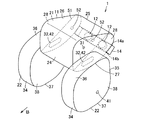
そして、エアバッグ11は、センタバッグ21と、このセンタバッグ21の両側部に連結された両側一対のサイドバッグ22との3個の互いに独立した基布製の袋体を連結して構成されている。
The
そして、センタバッグ21は、正面側である乗員側Bのほぼ全面に、頭部保護部24が設けられている。この頭部保護部24は、正面視四角形状の基布のパネルであり、エアバッグ11の膨張展開時にはセンタバッグ21の乗員側Bの先端部に位置して略垂直状に位置し、主として乗員Aの頭部A1に対向し、少なくとも一部が乗員Aの頭部A1に対向するようになっている。また、このセンタバッグ21は、乗員側Bの反対側の基端部25から、フロントガラス5に沿ってセンタバッグ21の上端部に延びるセンタバッグ上面部26と、基端部25からインストルメントパネル部4の上面部4aに沿い、さらに頭部保護部24の下端部に延びるセンタバッグ下面部27と、これら頭部保護部24、センタバッグ上面部26、及びセンタバッグ下面部27で囲まれた部分の両側部を覆う両側一対のセンタバッグ側面部28,28とを備えている。そして、センタバッグ下面部27には、基端部25近傍に位置して、ケース体14に取り付けられるとともに各インフレータ12が配置され、ガスが供給されてエアバッグ11の展開の起点となる基部30が設けられている。そして、この基部30には、インフレータ12の本体部が挿入される一対あるいは亜鈴状インフレータ挿入口がそれぞれ円孔状に形成されている。さらに、各センタバッグ側面部28には、先端部すなわち頭部保護部24近傍の上側部に位置して、円孔状のセンタバッグ排気口31が設けられ、先端部すなわち頭部保護部24近傍の下側部に位置して、円孔状の連通部32が形成されている。また、この連通部32は、センタバッグ排気口31よりも径寸法すなわち開口面積が大きく形成されている。
The
一方、両側一対のサイドバッグ22は、互いに対称形状で、正面側である乗員側Bのほぼ全面に、肩部保護部34が設けられている。この肩部保護部34は、正面視四角形状の基布のパネルであり、エアバッグ11の膨張展開時にはサイドバッグ22の乗員側Bの先端部に位置して乗員側Bに緩やかに膨出し、主として乗員Aの肩部A2に対向し、少なくとも一部が乗員Aの肩部A2に対向するようになっている。また、これらサイドバッグ22は、乗員側Bの反対側に位置するサイドバッグ基面部35を備えるとともに、このサイドバッグ基面部35と肩部保護部34との上端部同士を水平状に連続するサイドバッグ上面部36、下端部同士を水平状に連続するサイドバッグ下面部37、及びこれら肩部保護部34、サイドバッグ基面部35、サイドバッグ上面部36、及びサイドバッグ下面部37に囲まれた部分の両側部を覆う両側一対のサイドバッグ側面部38を備えている。そして、サイドバッグ側面部38の外側面すなわちセンタバッグ21とは反対側の面の下部には、円孔状のサイドバッグ排気口41が設けられ、サイドバッグ側面部38の内側面すなわちセンタバッグ21側の面の前部上側すなわちサイドバッグ基面部35側かつサイドバッグ上面部36に近接した位置には、円孔状の連通部42が形成されている。
On the other hand, the pair of
そして、これらセンタバッグ21及びサイドバッグ22は、図2に示すように、センタバッグ21の両側の連通部32に、それぞれサイドバッグ22の連通部42を位置合わせした状態で、これら連通部32,42を囲むように環状に縫合した接合部44により接合され、互いに独立した3個の袋体すなわち気室を備えるとともに連通部32,42で連通された立体形状のエアバッグ11が形成されている。
Then, as shown in FIG. 2, the
そして、このエアバッグ11は、基部30を支持してこの基部30からガスを導入し、他の部材に干渉しない自然状態で膨張展開させた状態で、図2に示すように、サイドバッグ22の肩部保護部34はセンタバッグ21の頭部保護部24よりも乗員側Bに位置し、サイドバッグ上面部36はセンタバッグ上面部26の上端部より下方に位置し、サイドバッグ下面部37はセンタバッグ下面部27の下端部よりも下方に位置し、サイドバッグ基面部35はセンタバッグ21の基端部25よりも乗員側Bに位置するようになっている。
The
なお、図2に示すエアバッグ11の状態は、他の部材に干渉しない自然状態で膨張展開させた状態を仮想的に示したもので、自動車2の車室で膨張展開する場合には、自動車2の部材や乗員Aに干渉され、変形した状態で膨張展開する。
Note that the state of the
なお、図示しないが、このエアバッグ11の各面部は、1枚の基布で形成される部分の他、補強布ないし防炎布などと呼ばれる基布を重ねて機械的及び熱的な強度の向上が図られた部分がある。また、折り畳んだエアバッグ11の形状を保持するとともにエアバッグ11の展開時に破断するラッピング部材であるシートが一体的に重ねて縫い合わされている。
Although not shown, each surface portion of the
そして、このように構成されたエアバッグ11は、リテーナプレートのリテーナ本体を基部30の内側に配置し、リテーナプレートの取付ボルトを取付孔から引き出した状態で、所定の形状に折り畳まれ、シートなどにより形状が保持される。そして、折り畳んだエアバッグ11をケース体14のエアバッグ収納部14bに収納するとともに、基部30にインフレ−タ12のガス噴射口を設けた本体部を挿入し、リテーナプレートの取付ボルトをインフレ−タ12のフランジ部及びケース体14の底部に設けた取付孔に挿入し、さらに取付ボルトの先端からナットを螺合して締め付ける。この状態で、リテーナ本体とナットとの間に、エアバッグ11の基部とケース体14、及びインフレ−タ12が共締めして固定され、エアバッグ装置1が構成される。
The
そして、このエアバッグ装置1は、自動車2のインストルメントパネル部4に取り付けられ、センサなどを備えた図示しない制御装置に電気的に接続される。 And this airbag apparatus 1 is attached to the instrument panel part 4 of the motor vehicle 2, and is electrically connected to the control apparatus which is not shown in figure provided with the sensor.
そして、このように構成されたエアバッグ装置1は、自動車2の衝突などの際に、制御装置がインフレ−タ12を作動させ、このインフレ−タ12からガスを噴射させる。すると、このエアバッグ11は、ガスの流入に伴い膨張展開し、カバー体のテアラインを破断して突出口14aから突出し、乗員側Bに向かい膨張展開して、助手席に着席した乗員Aの上半身の前方に膨張展開して、乗員Aを拘束して衝突の衝撃から保護する。
In the airbag device 1 configured as described above, the control device operates the inflator 12 and injects gas from the inflator 12 when the automobile 2 collides. Then, the
次に、エアバッグ11の展開過程をより詳細に説明する。
Next, the deployment process of the
まず、インフレータ12のガスは、センタバッグ21の基部30に直接に供給され、センタバッグ21を膨張展開させる。このセンタバッグ21は、インストルメントパネル部4の上面部4aとフロントガラス5との間に沿って乗員側Bに膨張展開し、展開初期に頭部保護部24を乗員Aの頭部A1に迅速に十分な反力で対向させ、必要に応じて乗員Aの頭部A1を初期拘束する。次いで、センタバッグ21の内側のガスは、連通部32,42を介して両側のサイドバッグ22に供給され、これらサイドバッグ22を膨張展開させる。各サイドバッグ22は、センタバッグ21の膨張展開によりエアバッグ収納部14bから引き出された状態からガスが供給され、肩部保護部34を乗員Aの肩部A2に対向させる。この状態で、シートベルトを装着して通常の状態で着席した乗員Aに対して、シートベルトが乗員Aの胸部A3を拘束するとともに、両側のサイドバッグ22の肩部保護部34が乗員Aの両側の肩部A2を拘束することにより、乗員Aの全体を安定して拘束し保護できる。さらに、肩部保護部34よりも乗員Aから見て若干後退し、かつ、ガスがサイドバッグ22側に抜けて反力が弱められたセンタバッグ21の頭部保護部24が、乗員Aの頭部A1を軟らかく拘束して保護する。そして、膨張展開したエアバッグ11のセンタバッグ21及びサイドバッグ22は、それぞれセンタバッグ排気口31及びサイドバッグ排気口41からガスが排気される。そして、エアバッグ11の展開過程において、乗員Aの胸部A3の中央部には、エアバッグ11は当接しないようになっている。
First, the gas in the
エアバッグ装置1の作動時の、センタバッグ21の圧力の変化のグラフを図3に示す。縦軸Gは圧力[kPa]、横軸tは時間[ミリ秒]である。また、実線Xは本実施の形態のエアバッグ11であり、実線Yは独立した3個の袋体を設けずに、センタバッグ21に相当する構造とサイドバッグ22に相当する構造とを一体の袋として構成したものである。このグラフに示すように、本実施の形態のエアバッグ11では、頭部保護部24について、ピーク圧力を低下させ、乗員Aの頭部A1を軟らかく拘束して保護できることが示された。
FIG. 3 shows a graph of changes in the pressure of the
また、エアバッグ装置1の作動時の、乗員Aのダミーの胸部A3の変位量の変化のグラフを図4に示す。縦軸Lは移動量[ミリメートル]、横軸tは時間[ミリ秒]である。また、実線Xは本実施の形態のエアバッグ11であり、実線Yは独立した3個の袋体を設けずに、センタバッグ21に相当する構造とサイドバッグ22に相当する構造とを一体の袋として構成したものである。このグラフに示すように、本実施の形態のエアバッグ11では、乗員Aの胸部A3について、胸部A3の中央部へのエアバッグ11による荷重を抑制でき、胸部A3の圧迫を抑制できることが示された。
Further, FIG. 4 shows a graph of the change in the displacement amount of the dummy chest A3 of the occupant A when the airbag apparatus 1 is operated. The vertical axis L is the movement amount [millimeter], and the horizontal axis t is the time [millisecond]. Further, the solid line X is the
また、図2に2点鎖線で示すように、女性など小柄な乗員Cについても、乗員Aと同様に、頭部と肩部とを支持して保護する。 Further, as shown by a two-dot chain line in FIG. 2, a small passenger C such as a woman also supports and protects the head and shoulders like the passenger A.
このように、本実施の形態によれば、ガスが流入してインストルメントパネル部4から乗員Aの上半身の前方に対向してエアバッグ11を膨張展開する助手席乗員用のエアバッグ装置1について、エアバッグ11は、1個の袋体の内側を区画するのではなく、乗員Aの頭部A1及び両側の肩部A2を拘束する3個の互いに独立した袋体として、乗員Aの頭部A1に対向するセンタバッグ21と両側の肩部A2に対向するサイドバッグ22とを備えたため、センタバッグ21及びサイドバッグ22の展開位置、乗員Aを拘束するタイミング、及び反力を容易に異なる所望の値に調整でき、頭部A1及び肩部A2に対してそれぞれ好ましい特性を容易に実現して乗員を保護できる。
Thus, according to the present embodiment, the airbag device 1 for a passenger on the passenger seat that inflates and deploys the
すなわち、頭部A1を保護する頭部保護部24を設けたセンタバッグ21を、肩部A2の保護に高い圧力が必要となる肩部保護部34を設けたサイドバッグ22とは別体としたため、センタバッグ21のピーク圧力を抑制して頭部A1を柔らかく拘束できるとともに、十分な反力のサイドバッグ22で両側の肩部A2を拘束することにより、乗員Aの体全体の移動を十分に抑えて保護できる。さらに、エアバッグ11は胸部A3の中央部を拘束せず、通常シートベルトにより拘束されて圧力が加わる胸部A3の中央部にさらに力が加わることを防止して、乗員Aを保護できる。すなわち、乗員Aの頭部A1を柔軟に拘束する特性と肩部A2を十分に拘束する特性とがトレードオフの関係にならず、乗員Aの頭部A1を柔軟に拘束する特性と肩部A2を十分に拘束する特性とを容易に両立できる。
That is, the
また、連通部32,42を介してセンタバッグ21からサイドバッグ22にガスを供給する構造により、乗員Aの頭部A1の拘束について、展開初期にはセンタバッグ21を十分に膨張展開させて反力を十分に確保し、完全展開時(完全拘束時)にはセンタバッグ21の反力を小さくするとの、展開初期と完全拘束時とでエアバッグ11の反力を変化させ適切な反力で保護する好ましい特性を容易に実現できる。
Further, the structure in which the gas is supplied from the
また、エアバッグ11が膨張展開した状態で、サイドバッグ22の肩部保護部34をセンタバッグ21の頭部保護部24よりも乗員側Bに位置させたため、頭部保護部24よりも乗員側Bに位置する肩部保護部34で乗員Aを十分に拘束して乗員Aを保護できる。ここで、センタバッグ21とサイドバッグ22とは別体であるため、頭部保護部24と肩部保護部34との位置の調整を容易に実現できる。
Further, since the
また、センタバッグ21及びサイドバッグ22の形状は、内部の区画を要しないとともにそれぞれ凹凸の少ない単純な形状であり、また、センタバッグ21の基部30にガスを供給することにより、連通部32,42を介してセンタバッグ21からサイドバッグ22にガスを供給でき、エアバッグ11の構造を簡略化して製造コストを低減できる。
Further, the shape of the
また、このエアバッグ11は、インストルメントパネル部4の上面部4aに取り付けられ、センタバッグ21はこの上面部4aとフロントガラス5との間に浅い角度で支持され、仮にこのセンタバッグ21で乗員Aの肩部A2を支えるためには、エアバッグ11の容量を大きくする必要が生じる場合があるが、基端部25が他の部材に支えられない状態となるが、少なくとも一部がセンタバッグ21より下方に膨張展開してインストルメントパネル部4の正面部4bと乗員Aの肩部A2との間に膨張展開するサイドバッグ22により、乗員Aの肩部A2を十分な反力で安定して拘束できる。そこで、エアバッグ11は、センタバッグ21をインストルメントパネル部4の上面部4aの前端まで膨張展開する必要がなく、エアバッグ11の容量を小さくして、エアバッグ装置1の小形化、軽量化を容易に実現できる。
The
また、上記のように好ましい展開特性を容易に実現できるため、排気口31,41の位置や大きさの設定により反力を調整する度合いを小さくできる。そこで、排気口31,41を、排気が乗員Aに影響を与えない位置に自由に設定することができる。
In addition, since preferable development characteristics can be easily realized as described above, the degree of adjusting the reaction force can be reduced by setting the positions and sizes of the
なお、上記の実施の形態では、連通部32,42は、円孔状としたが、この構成に限られず、例えば図5に示すように、前後方向すなわち乗員側Bに向かう方向に沿った方向を長手方向とする長孔状とすることもできる。 In the above embodiment, the communication portions 32 and 42 are circular holes, but are not limited to this configuration. For example, as shown in FIG. 5, the direction along the front-rear direction, that is, the direction toward the passenger side B It can also be made into the shape of a long hole with a longitudinal direction.
また、頭部保護部24を設けたセンタバッグ21と肩部保護部34を設けたサイドバッグ22とは別体であるため、これら頭部保護部24と肩部保護部34との前後あるいは上下などの位置関係は車室の形状などに応じて容易に自由に設定できる。例えば、図6に示すように、頭部保護部24と肩部保護部34とを同一面に設定することもできる。あるいは、図7に示すように、肩部保護部34よりも頭部保護部24をより乗員側Bに位置させることもできる。
In addition, since the
また、サイドバッグ22よりもセンタバッグ21を先に膨張展開させる構成に限られず、ガスの流れを制御することにより、サイドバッグ22とセンタバッグ21とを同時に展開させ、あるいは、センタバッグ21よりもサイドバッグ22を先に膨張展開させることもできる。
In addition, the configuration is not limited to the configuration in which the
例えば、図8ないし図10に示すように、センタバッグ21の内側に、このセンタバッグ21の内側を区画する基布である案内部51を設けることができる。この案内部51は、基部30に対向するようにして、センタバッグ21のセンタバッグ上面部26の基端部25近傍と、センタバッグ下面部27の頭部保護部24近傍とを連結するように配置され、センタバッグ21の内側を基部30側と頭部保護部24とに区画している。そして、連通部32,42は、案内部51の基部30側に配置されるとともに、案内部51には、連通部32,42よりも開口面積が小さく、すなわち通気抵抗が大きい通気部52が本実施の形態では2カ所の円孔として形成されている。そこで、この構成では、図9に矢印Fで示すように、基部30から供給されたガスは案内部51に案内され、センタバッグ21の頭部保護部24側よりもサイドバッグ22に多く供給され、肩部保護部34を設けたサイドバッグ22が頭部保護部24を設けたセンタバッグ21よりも先に十分な反力で乗員側Bに膨張展開する。そこで、この構成では、頭部保護部24の内圧すなわち反力を小さくして、乗員Aの頭部A1をより柔軟に拘束することが容易になる。
For example, as shown in FIGS. 8 to 10, a
本発明は、例えば、車両の助手席乗員用のエアバッグ装置の他、前席の座席の後部から、後席の座席の乗員の上半身に向かって展開するエアバッグを備えたエアバッグ装置に適用できる。 The present invention is applied to, for example, an airbag apparatus provided with an airbag that is deployed from the rear part of the front seat to the upper body of the occupant of the rear seat in addition to the airbag apparatus for the passenger on the passenger seat of the vehicle. it can.
1 エアバッグ装置
2 車両としての自動車
4 インストルメントパネル部
4a 上面部
4b 正面部
11 エアバッグ
12 インフレータ
14 被取付部材を構成するケース体
21 センタバッグ
22 サイドバッグ
24 頭部保護部
30 基部
32,42 連通部
34 肩部保護部
A 乗員
A1 頭部
A2 肩部
B 乗員側
DESCRIPTION OF SYMBOLS 1 Airbag apparatus 2 Car as vehicle 4 Instrument panel part 4a Upper surface part 4b Front part
11 Airbag
12 Inflator
14 Case body constituting the mounted member
21 Center bag
22 Side bag
24 Head protector
30 base
32, 42 communication part
34 Shoulder Protection A A Crew A1 Head A2 Shoulder B Crew
Claims (4)
前記乗員の頭部に対向する頭部保護部を設けた袋状のセンタバッグと、
それぞれ前記乗員の肩部に対向する肩部保護部を設け前記センタバッグの両側部に連結されかつ前記センタバックとは独立した袋状をなす一対のサイドバッグと
を具備したことを特徴とするエアバッグ。 An airbag that inflates and deploys against the upper body of an occupant when gas flows in,
A bag-shaped center bag provided with a head protection portion facing the head of the occupant;
An air comprising a pair of side bags each provided with a shoulder protection portion facing the shoulder portion of the occupant and connected to both sides of the center bag and forming a bag shape independent of the center bag. bag.
前記センタバッグに設けられガスが導入されるとともに被取付部材に取り付けられる基部と
を具備したことを特徴とする請求項1記載のエアバッグ。 A communication portion for communicating the center bag and the side bags on both sides;
The airbag according to claim 1, further comprising: a base portion that is provided in the center bag and into which gas is introduced and is attached to the attached member.
ことを特徴とする請求項1または2記載のエアバッグ。 The airbag according to claim 1 or 2, wherein the shoulder protection part is positioned closer to the passenger than the head protection part in a state where the airbag is inflated and deployed.
請求項1ないし3いずれか一記載のエアバッグと、このエアバッグにガスを供給するインフレ−タとを具備し、
前記エアバッグは、着席した乗員の上半身の正面側に対向して膨張展開し、センタバッグは、前記インストルメントパネル部の上面部に取り付けられ、サイドバッグは、少なくとも一部が前記センタバッグより下方に膨張展開し、前記インストルメントパネル部の正面部と乗員との間に膨張展開する
ことを特徴とするエアバッグ装置。 An airbag device installed in an instrument panel portion of a vehicle,
An airbag according to any one of claims 1 to 3, and an inflator for supplying gas to the airbag,
The airbag is inflated and deployed facing the front side of the upper body of a seated occupant, the center bag is attached to the upper surface of the instrument panel, and the side bag is at least partially below the center bag. The airbag device is inflated and deployed between the front portion of the instrument panel portion and an occupant.
Priority Applications (1)
| Application Number | Priority Date | Filing Date | Title |
|---|---|---|---|
| JP2009047168A JP5366591B2 (en) | 2009-02-27 | 2009-02-27 | Air bag and air bag device |
Applications Claiming Priority (1)
| Application Number | Priority Date | Filing Date | Title |
|---|---|---|---|
| JP2009047168A JP5366591B2 (en) | 2009-02-27 | 2009-02-27 | Air bag and air bag device |
Publications (2)
| Publication Number | Publication Date |
|---|---|
| JP2010201980A true JP2010201980A (en) | 2010-09-16 |
| JP5366591B2 JP5366591B2 (en) | 2013-12-11 |
Family
ID=42963910
Family Applications (1)
| Application Number | Title | Priority Date | Filing Date |
|---|---|---|---|
| JP2009047168A Active JP5366591B2 (en) | 2009-02-27 | 2009-02-27 | Air bag and air bag device |
Country Status (1)
| Country | Link |
|---|---|
| JP (1) | JP5366591B2 (en) |
Cited By (25)
| Publication number | Priority date | Publication date | Assignee | Title |
|---|---|---|---|---|
| JP2013082418A (en) * | 2011-10-05 | 2013-05-09 | Hyundai Motor Co Ltd | Vehicular roof air bag device |
| CN104908699A (en) * | 2014-03-13 | 2015-09-16 | 福特全球技术公司 | Passenger airbag with secondary chamber |
| US20150258959A1 (en) * | 2014-03-13 | 2015-09-17 | Ford Global Technologies, Llc | Passenger airbag with secondary chamber |
| CN104943649A (en) * | 2014-03-27 | 2015-09-30 | 福特全球技术公司 | Passenger airbag with secondary chamber |
| WO2015156088A1 (en) * | 2014-04-11 | 2015-10-15 | オートリブ ディベロップメント エービー | Airbag device |
| US9227587B1 (en) | 2015-01-26 | 2016-01-05 | Ford Global Technologies, Llc | Vehicle oblique impact absorbing system |
| WO2016002384A1 (en) * | 2014-06-30 | 2016-01-07 | オートリブ ディベロップメント エービー | Airbag device |
| JP2016020116A (en) * | 2014-07-11 | 2016-02-04 | トヨタ自動車株式会社 | Passenger seat airbag device for vehicle |
| JP2016020174A (en) * | 2014-07-15 | 2016-02-04 | タカタ株式会社 | Air bag |
| JP2016049882A (en) * | 2014-08-29 | 2016-04-11 | トヨタ自動車株式会社 | Passenger airbag device |
| US9358945B2 (en) | 2014-08-12 | 2016-06-07 | Toyoda Gosei Co., Ltd. | Airbag device for a front passenger seat |
| JP2016153262A (en) * | 2015-02-20 | 2016-08-25 | オートリブ ディベロップメント エービー | Air bag device |
| US9566929B1 (en) | 2015-12-15 | 2017-02-14 | Ford Global Technologies, Llc | Vehicle oblique impact absorbing system |
| US9796354B1 (en) | 2016-03-30 | 2017-10-24 | Toyoda Gosei Co., Ltd. | Airbag device for front passenger seat |
| JP2018079709A (en) * | 2016-11-14 | 2018-05-24 | 日本プラスト株式会社 | Airbag |
| JP2018134975A (en) * | 2017-02-22 | 2018-08-30 | マツダ株式会社 | Airbag device |
| JP2018158728A (en) * | 2018-07-17 | 2018-10-11 | オートリブ ディベロップメント エービー | Airbag device |
| US10166946B2 (en) | 2014-03-31 | 2019-01-01 | Autoliv Development Ab | Vehicular airbag device |
| US10246039B2 (en) | 2014-04-25 | 2019-04-02 | Autoliv Development Ab | Airbag device |
| US10246042B2 (en) | 2014-06-25 | 2019-04-02 | Autoliv Development Ab | Air bag device |
| US10358106B2 (en) | 2014-08-04 | 2019-07-23 | Autoliv Development Ab | Airbag apparatus |
| WO2019155801A1 (en) * | 2018-02-07 | 2019-08-15 | Joyson Safety Systems Japan株式会社 | Air bag and air bag device |
| US11186250B2 (en) | 2017-09-21 | 2021-11-30 | Joyson Safety Systems Japan K.K. | Air bag and air bag device |
| US11192513B2 (en) | 2017-03-30 | 2021-12-07 | Joyson Safety Systems Japan K.K. | Airbag and airbag device |
| US20240190379A1 (en) * | 2022-12-13 | 2024-06-13 | Subaru Corporation | Occupant protection device |
Families Citing this family (4)
| Publication number | Priority date | Publication date | Assignee | Title |
|---|---|---|---|---|
| US9969349B2 (en) | 2014-04-24 | 2018-05-15 | Ford Global Technologies, Llc | Passenger airbag with extended base |
| US10155496B2 (en) * | 2016-12-09 | 2018-12-18 | Ford Global Technologies, Llc | Airbag with side chambers |
| US10183645B2 (en) | 2017-03-01 | 2019-01-22 | Autoliv Asp, Inc. | Frontal airbag systems for oblique impact |
| JP2024084247A (en) * | 2022-12-13 | 2024-06-25 | 株式会社Subaru | Occupant protection devices |
Citations (5)
| Publication number | Priority date | Publication date | Assignee | Title |
|---|---|---|---|---|
| JP2003327184A (en) * | 2002-05-15 | 2003-11-19 | Takata Corp | Air bag device for motorcycle, manufacturing method of air bag device for motorcycle and motorcycle with air bag device |
| JP2005145225A (en) * | 2003-11-14 | 2005-06-09 | Takata Corp | Passenger protecting device, and vehicle |
| JP2005280470A (en) * | 2004-03-29 | 2005-10-13 | Toyoda Gosei Co Ltd | Air bag for front passenger seat |
| WO2006082900A1 (en) * | 2005-02-07 | 2006-08-10 | Autoliv Development Ab | Air bag device |
| JP2008044480A (en) * | 2006-08-11 | 2008-02-28 | Takata Corp | Airbag device |
-
2009
- 2009-02-27 JP JP2009047168A patent/JP5366591B2/en active Active
Patent Citations (5)
| Publication number | Priority date | Publication date | Assignee | Title |
|---|---|---|---|---|
| JP2003327184A (en) * | 2002-05-15 | 2003-11-19 | Takata Corp | Air bag device for motorcycle, manufacturing method of air bag device for motorcycle and motorcycle with air bag device |
| JP2005145225A (en) * | 2003-11-14 | 2005-06-09 | Takata Corp | Passenger protecting device, and vehicle |
| JP2005280470A (en) * | 2004-03-29 | 2005-10-13 | Toyoda Gosei Co Ltd | Air bag for front passenger seat |
| WO2006082900A1 (en) * | 2005-02-07 | 2006-08-10 | Autoliv Development Ab | Air bag device |
| JP2008044480A (en) * | 2006-08-11 | 2008-02-28 | Takata Corp | Airbag device |
Cited By (41)
| Publication number | Priority date | Publication date | Assignee | Title |
|---|---|---|---|---|
| JP2013082418A (en) * | 2011-10-05 | 2013-05-09 | Hyundai Motor Co Ltd | Vehicular roof air bag device |
| US9340176B2 (en) * | 2014-03-13 | 2016-05-17 | Ford Global Technologies, Llc | Passenger airbag with secondary chamber |
| CN104908699A (en) * | 2014-03-13 | 2015-09-16 | 福特全球技术公司 | Passenger airbag with secondary chamber |
| US20150258959A1 (en) * | 2014-03-13 | 2015-09-17 | Ford Global Technologies, Llc | Passenger airbag with secondary chamber |
| CN104908699B (en) * | 2014-03-13 | 2019-03-22 | 福特全球技术公司 | Airbag with concubine |
| CN104943649A (en) * | 2014-03-27 | 2015-09-30 | 福特全球技术公司 | Passenger airbag with secondary chamber |
| RU2657644C2 (en) * | 2014-03-27 | 2018-06-14 | Форд Глобал Технолоджис, ЛЛК | Vehicle airbag with additional chamber |
| US11351951B2 (en) | 2014-03-31 | 2022-06-07 | Autoliv Development Ab | Vehicular airbag device |
| US10166946B2 (en) | 2014-03-31 | 2019-01-01 | Autoliv Development Ab | Vehicular airbag device |
| US10836344B2 (en) | 2014-03-31 | 2020-11-17 | Autoliv Development Ab | Vehicular airbag device |
| CN110077351A (en) * | 2014-04-11 | 2019-08-02 | 奥托立夫开发公司 | Airbag apparatus |
| CN106163884A (en) * | 2014-04-11 | 2016-11-23 | 奥托立夫开发公司 | airbag device |
| CN106163884B (en) * | 2014-04-11 | 2019-04-16 | 奥托立夫开发公司 | Airbag device |
| JPWO2015156088A1 (en) * | 2014-04-11 | 2017-04-13 | オートリブ ディベロップメント エービー | Airbag device |
| CN110077351B (en) * | 2014-04-11 | 2021-09-21 | 奥托立夫开发公司 | Airbag device |
| US10059299B2 (en) | 2014-04-11 | 2018-08-28 | Autoliv Development Ab | Airbag device |
| WO2015156088A1 (en) * | 2014-04-11 | 2015-10-15 | オートリブ ディベロップメント エービー | Airbag device |
| US10246039B2 (en) | 2014-04-25 | 2019-04-02 | Autoliv Development Ab | Airbag device |
| US10246042B2 (en) | 2014-06-25 | 2019-04-02 | Autoliv Development Ab | Air bag device |
| US10023144B2 (en) | 2014-06-30 | 2018-07-17 | Autoliv Development Ab | Airbag device |
| WO2016002384A1 (en) * | 2014-06-30 | 2016-01-07 | オートリブ ディベロップメント エービー | Airbag device |
| JPWO2016002384A1 (en) * | 2014-06-30 | 2017-04-27 | オートリブ ディベロップメント エービー | Airbag device |
| JP2018135098A (en) * | 2014-06-30 | 2018-08-30 | オートリブ ディベロップメント エービー | Airbag device |
| JP2016020116A (en) * | 2014-07-11 | 2016-02-04 | トヨタ自動車株式会社 | Passenger seat airbag device for vehicle |
| JP2016020174A (en) * | 2014-07-15 | 2016-02-04 | タカタ株式会社 | Air bag |
| US10358106B2 (en) | 2014-08-04 | 2019-07-23 | Autoliv Development Ab | Airbag apparatus |
| US9358945B2 (en) | 2014-08-12 | 2016-06-07 | Toyoda Gosei Co., Ltd. | Airbag device for a front passenger seat |
| JP2016049882A (en) * | 2014-08-29 | 2016-04-11 | トヨタ自動車株式会社 | Passenger airbag device |
| US9227587B1 (en) | 2015-01-26 | 2016-01-05 | Ford Global Technologies, Llc | Vehicle oblique impact absorbing system |
| JP2016153262A (en) * | 2015-02-20 | 2016-08-25 | オートリブ ディベロップメント エービー | Air bag device |
| US9566929B1 (en) | 2015-12-15 | 2017-02-14 | Ford Global Technologies, Llc | Vehicle oblique impact absorbing system |
| US9796354B1 (en) | 2016-03-30 | 2017-10-24 | Toyoda Gosei Co., Ltd. | Airbag device for front passenger seat |
| JP2018079709A (en) * | 2016-11-14 | 2018-05-24 | 日本プラスト株式会社 | Airbag |
| JP2018134975A (en) * | 2017-02-22 | 2018-08-30 | マツダ株式会社 | Airbag device |
| US11192513B2 (en) | 2017-03-30 | 2021-12-07 | Joyson Safety Systems Japan K.K. | Airbag and airbag device |
| US11186250B2 (en) | 2017-09-21 | 2021-11-30 | Joyson Safety Systems Japan K.K. | Air bag and air bag device |
| WO2019155801A1 (en) * | 2018-02-07 | 2019-08-15 | Joyson Safety Systems Japan株式会社 | Air bag and air bag device |
| JP2019137129A (en) * | 2018-02-07 | 2019-08-22 | Joyson Safety Systems Japan株式会社 | Air bag and air bag device |
| JP2018158728A (en) * | 2018-07-17 | 2018-10-11 | オートリブ ディベロップメント エービー | Airbag device |
| US20240190379A1 (en) * | 2022-12-13 | 2024-06-13 | Subaru Corporation | Occupant protection device |
| US12162422B2 (en) * | 2022-12-13 | 2024-12-10 | Subaru Corporation | Occupant protection device |
Also Published As
| Publication number | Publication date |
|---|---|
| JP5366591B2 (en) | 2013-12-11 |
Similar Documents
| Publication | Publication Date | Title |
|---|---|---|
| JP5366591B2 (en) | Air bag and air bag device | |
| US11833990B2 (en) | Side airbag device, vehicle seat provided with same, and method for manufacturing side airbag device | |
| JP4285167B2 (en) | Side airbag device | |
| JP6149840B2 (en) | Far-side airbag device for vehicles | |
| JP6574554B2 (en) | Airbag | |
| US9783149B2 (en) | Side airbag device | |
| JP6866826B2 (en) | Rear seat side airbag device | |
| JP2018012476A (en) | Vehicular occupant restraint device | |
| CN112533798B (en) | Side airbag device | |
| JP7427780B2 (en) | air bag device | |
| JP7568834B2 (en) | Side airbag device | |
| JP5483568B2 (en) | Airbag | |
| JP2019098921A (en) | Rear seat side air bag device | |
| CN111845613B (en) | side air bag device | |
| JP2025000977A (en) | Side air bag device | |
| JP5419261B2 (en) | Air bag and air bag device | |
| JP5455789B2 (en) | Airbag | |
| JP4122196B2 (en) | Airbag device | |
| JP2009107577A (en) | Airbag and airbag device | |
| WO2024053518A1 (en) | Occupant protection device | |
| JP5053520B2 (en) | Airbag | |
| JP4974371B2 (en) | Air bag and air bag device | |
| JP5184312B2 (en) | Air bag and air bag device | |
| JP5171707B2 (en) | Airbag device | |
| WO2025089097A1 (en) | Vehicle side airbag device |
Legal Events
| Date | Code | Title | Description |
|---|---|---|---|
| A621 | Written request for application examination |
Free format text: JAPANESE INTERMEDIATE CODE: A621 Effective date: 20120127 |
|
| A977 | Report on retrieval |
Free format text: JAPANESE INTERMEDIATE CODE: A971007 Effective date: 20121210 |
|
| A131 | Notification of reasons for refusal |
Free format text: JAPANESE INTERMEDIATE CODE: A131 Effective date: 20130206 |
|
| A521 | Request for written amendment filed |
Free format text: JAPANESE INTERMEDIATE CODE: A523 Effective date: 20130401 |
|
| TRDD | Decision of grant or rejection written | ||
| A01 | Written decision to grant a patent or to grant a registration (utility model) |
Free format text: JAPANESE INTERMEDIATE CODE: A01 Effective date: 20130904 |
|
| A61 | First payment of annual fees (during grant procedure) |
Free format text: JAPANESE INTERMEDIATE CODE: A61 Effective date: 20130910 |
|
| R150 | Certificate of patent or registration of utility model |
Free format text: JAPANESE INTERMEDIATE CODE: R150 Ref document number: 5366591 Country of ref document: JP Free format text: JAPANESE INTERMEDIATE CODE: R150 |
|
| R250 | Receipt of annual fees |
Free format text: JAPANESE INTERMEDIATE CODE: R250 |
|
| R250 | Receipt of annual fees |
Free format text: JAPANESE INTERMEDIATE CODE: R250 |
|
| R250 | Receipt of annual fees |
Free format text: JAPANESE INTERMEDIATE CODE: R250 |
|
| R250 | Receipt of annual fees |
Free format text: JAPANESE INTERMEDIATE CODE: R250 |
|
| R250 | Receipt of annual fees |
Free format text: JAPANESE INTERMEDIATE CODE: R250 |
|
| R250 | Receipt of annual fees |
Free format text: JAPANESE INTERMEDIATE CODE: R250 |
|
| R250 | Receipt of annual fees |
Free format text: JAPANESE INTERMEDIATE CODE: R250 |
|
| R250 | Receipt of annual fees |
Free format text: JAPANESE INTERMEDIATE CODE: R250 |
|
| R250 | Receipt of annual fees |
Free format text: JAPANESE INTERMEDIATE CODE: R250 |
|
| R250 | Receipt of annual fees |
Free format text: JAPANESE INTERMEDIATE CODE: R250 |