JP2010219085A - Heat sink for natural air cooling - Google Patents
Heat sink for natural air cooling Download PDFInfo
- Publication number
- JP2010219085A JP2010219085A JP2009060571A JP2009060571A JP2010219085A JP 2010219085 A JP2010219085 A JP 2010219085A JP 2009060571 A JP2009060571 A JP 2009060571A JP 2009060571 A JP2009060571 A JP 2009060571A JP 2010219085 A JP2010219085 A JP 2010219085A
- Authority
- JP
- Japan
- Prior art keywords
- heat
- heat sink
- fin
- air cooling
- natural air
- Prior art date
- Legal status (The legal status is an assumption and is not a legal conclusion. Google has not performed a legal analysis and makes no representation as to the accuracy of the status listed.)
- Pending
Links
Images


Landscapes
- Cooling Or The Like Of Electrical Apparatus (AREA)
- Cooling Or The Like Of Semiconductors Or Solid State Devices (AREA)
Abstract
Description
この発明は、強制冷却用の送風ファン等を使用しない自然空冷用ヒートシンク、特に自然対流を生起させる自然空冷用ヒートシンクおよびそれを用いた自然空冷用冷却装置に関する。 The present invention relates to a natural air cooling heat sink that does not use a forced cooling fan or the like, and more particularly to a natural air cooling heat sink that causes natural convection and a natural air cooling cooling device using the same.
近年、IC、CPU等がパソコン等の特殊な製品だけでなく、家電製品等の広い分野で使用されるようになり、筐体内に内蔵された、CPU等の各種発熱部品の熱を、効率よく放熱することができる冷却装置が要求されている。
従来、このような冷却装置の一種として、ヒートシンクが用いられている。ヒートシンクの性能を向上させるためには、例えば特許文献1に記載されているように、一方の面に発熱素子が熱的に接続される受熱プレートの他方の面に放熱フィンを接合して形成されたヒートシンクに、放熱フィン間を冷却風が通るように電動ファンを取り付けて、ファンの回転によって放熱フィン間に強制的に冷却風を送り込んで、発熱素子から伝わった熱を大気中に放散する強制空冷タイプのヒートシンクが利用されている。
In recent years, ICs, CPUs, etc. have been used not only in special products such as personal computers but also in a wide range of fields such as home appliances. There is a need for a cooling device that can dissipate heat.
Conventionally, a heat sink has been used as one type of such a cooling device. In order to improve the performance of the heat sink, for example, as described in
このような強制空冷タイプのヒートシンクでは、一層優れた放熱効果を求めて、ファンを高速回転させ、または、大型ファンを利用する等の改善が進められている。例えば、特許文献1に記載の発明では、ヒートシンク上に所定の距離を隔ててカバーを設けることによって、フィン間に流れる送風量を増加させ、冷却効率を改善することが記載されている(図10参照)。
In such a forced air cooling type heat sink, improvements such as a high-speed rotation of a fan or use of a large fan are being pursued in order to obtain a further excellent heat dissipation effect. For example, in the invention described in
また、ヒートシンクが家電製品等の広い分野で使用されるようになったことで、更に低コストで効率的な冷却装置が要求されている。
ヒートシンクの低コスト化のため、従来、製造コストの安価なアルミニウムの押し出し材によるヒートシンクが利用されてきた。押し出し材によるヒートシンクは、受熱ブロックと放熱フィンとが一体的に形成されるので、製造が容易であるため、広く用いられてきた。
In addition, since heat sinks have been used in a wide range of home appliances and the like, there is a need for an efficient cooling device that is even lower in cost.
In order to reduce the cost of the heat sink, conventionally, a heat sink using an extruded aluminum material, which is inexpensive to manufacture, has been used. A heat sink made of an extruded material has been widely used because the heat receiving block and the heat radiating fin are integrally formed, and is easy to manufacture.
しかしながら、電動ファンは、強制的に冷却風を放熱フィン間に送り込むことができるため、発熱部品からヒートシンクに伝わった熱を効果的に空気中に放散し、冷却することができるが、ファンの回転に伴う騒音の発生、更に、ファンを取り付けることによる高コスト等の問題点がある。 However, since the electric fan can forcibly send cooling air between the heat dissipation fins, the heat transmitted from the heat-generating parts to the heat sink can be effectively dissipated into the air and cooled, but the rotation of the fan In addition, there are problems such as the generation of noise and the high cost due to the installation of a fan.
また、押し出し材によるヒートシンクは、断面が同じ形状のヒートシンクであり、種々の目的に応じて受熱ブロックおよび放熱フィンの形状を変更しようとすると、研削加工等が必要となり、コストアップの問題があった。 In addition, the heat sink made of extruded material is a heat sink having the same shape in cross section, and when trying to change the shape of the heat receiving block and the heat radiating fins according to various purposes, there is a problem of cost increase because grinding is required. .
このような押出材によるヒートシンクは、放熱性能を高めるため、筐体の大きさ等、配置される場所に応じて最大限の大きさで設計される。そのため、ヒートシンクはフィンの上端部が、筐体の内壁に近接するように配置されるため、ヒートシンクの周辺の空気の対流は、隣接するフィン間に限定されて流速が制限され、効果的に放熱することができなかった。 Such a heat sink made of an extruded material is designed with the maximum size according to the place where it is placed, such as the size of the housing, in order to enhance the heat dissipation performance. Therefore, since the heat sink is arranged so that the upper end of the fin is close to the inner wall of the housing, the air convection around the heat sink is limited between adjacent fins and the flow velocity is limited, effectively radiating heat. I couldn't.
従って、この発明の目的は、強制冷却用の送風ファン等を使用しない自然空冷用ヒートシンクであっても、発熱素子からの熱を効果的に放熱することができるヒートシンクを提供することにある。 Accordingly, an object of the present invention is to provide a heat sink that can effectively dissipate heat from the heating element, even if it is a natural air cooling heat sink that does not use a forced cooling fan or the like.
本発明の自然空冷用ヒートシンクの第1の態様は、筐体内の発熱素子を冷却するための自然空冷用ヒートシンクであって、一方の面が発熱素子に熱的に接続されるベースプレートと、その下端部が、前記ベースプレートの他方の面に熱的に接続された複数のフィンからなる放熱フィン部とを備え、前記フィンは、前記発熱素子に対応する部分の上端部近傍に一つ以上の切欠き部を有することを特徴とする。 A first aspect of a natural air cooling heat sink according to the present invention is a natural air cooling heat sink for cooling a heat generating element in a housing, a base plate having one surface thermally connected to the heat generating element, and a lower end thereof. A heat radiating fin portion comprising a plurality of fins thermally connected to the other surface of the base plate, and the fin has one or more notches in the vicinity of the upper end portion of the portion corresponding to the heating element. It has the part.
本発明の自然空冷用ヒートシンクの別の態様は、前記フィンは、前記切欠き部の一の辺に、前記切欠き部の形状に対応する切り起し部を有することを特徴とする。 Another aspect of the natural air cooling heat sink according to the present invention is characterized in that the fin has a cut-and-raised portion corresponding to the shape of the notch on one side of the notch.
本発明の自然空冷用ヒートシンクの別の態様は、前記切欠き部は、前記フィンの上辺を一辺とする矩形状であり、前記一の辺は、前記上辺に隣接する辺のいずれか一方であることを特徴とする。 In another aspect of the natural air cooling heat sink of the present invention, the notch has a rectangular shape with the upper side of the fin as one side, and the one side is one of the sides adjacent to the upper side. It is characterized by that.
本発明の自然空冷用ヒートシンクの別の態様は、前記フィンは、前記ベースプレートに熱的に接続される受熱部と、前記受熱部から立ち上がる放熱部とを備えた断面略L字形状の金属薄板であることを特徴とする。 In another aspect of the natural air cooling heat sink of the present invention, the fin is a thin metal plate having a substantially L-shaped cross section including a heat receiving part thermally connected to the base plate and a heat radiating part rising from the heat receiving part. It is characterized by being.
本発明の自然空冷用ヒートシンクの別の態様は、前記フィンは、前記ベースプレートに熱的に接続される受熱部と、前記受熱部から立ち上がる第1放熱部と、前記フィンの上辺近傍に形成され前記筐体に熱的に接続される第2放熱部とを備えた金属薄板であることを特徴とする。 In another aspect of the natural air cooling heat sink of the present invention, the fin is formed near a top side of the fin, a heat receiving part thermally connected to the base plate, a first heat radiating part rising from the heat receiving part, It is a metal thin plate provided with the 2nd thermal radiation part thermally connected to a housing | casing, It is characterized by the above-mentioned.
本発明の自然空冷用ヒートシンクの別の態様は、前記フィンは、前記第1放熱部に、前記受熱部と前記第2放熱部との間にかかる応力を緩和する弾性変形部を備えることを特徴とする。 According to another aspect of the heat sink for natural air cooling of the present invention, the fin includes an elastic deformation portion that relaxes stress applied between the heat receiving portion and the second heat radiating portion in the first heat radiating portion. And
本発明によれば、強制冷却用の送風ファン等を使用しない自然空冷用ヒートシンクであっても、筐体内の熱の対流を促進することができるため、発熱素子からの熱を効果的に放熱することができる。 According to the present invention, even if it is a natural air cooling heat sink that does not use a forced cooling fan or the like, heat convection in the housing can be promoted, so that heat from the heating element is effectively radiated. be able to.
本発明の好ましい実施の形態における自然空冷用ヒートシンクについて、図面を参照して詳細に説明する。なお、同一機能を有する各構成部については、図示及び説明簡略化のため、同一符号を付して示す。 A natural air cooling heat sink according to a preferred embodiment of the present invention will be described in detail with reference to the drawings. In addition, about each structural part which has the same function, the same code | symbol is attached | subjected and shown for simplification of illustration and description.
(第1の実施形態)
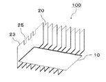
図1は、本発明の第1の実施形態に係る自然空冷用ヒートシンクの斜視図である。図1に示すように、自然空冷用ヒートシンク100は、一方の面が図示しない発熱素子(被冷却素子)に熱的に接続されるベースプレート10と、ベースプレート10の他方の面に熱的に接続される複数のフィン20が並列に立設された放熱フィン部とを備えている。また、フィン20は、ベースプレート10の発熱素子が取り付けられる部分に対応した部分の上端部23の近傍に切欠き部25を備えている。
(First embodiment)
FIG. 1 is a perspective view of a natural air cooling heat sink according to the first embodiment of the present invention. As shown in FIG. 1, the natural air
ベースプレート10は、例えば0.2〜3.0mm程度の厚さの熱伝導性に優れた金属板(例えば、銅、アルミニウム、銅−タングステン合金等)で形成されている。また、フィン20は、例えば0.1〜1.0mm程度の厚さの熱伝導性に優れた金属板で形成されている。ベースプレート10とフィン20とは、後述する様々な方法によって熱的に接続されている。
ベースプレート10及びフィンの縦、横の長さは、配置される発熱素子の形状、筐体の大きさ等によって適宜設計される。
The
The vertical and horizontal lengths of the
フィン20に形成された切欠き部25としては、三角形、四角形、台形等の多角形、円弧等、様々な形状を採用することができるが、放熱性および製造の容易性を考慮すると四角形(矩形)が特に好ましい。また、切欠き部25は、少なくとも、発熱素子が取付けられる部分に配置されたフィンに形成されていれば良いが、全てのフィンに形成されていることが望ましい。
As the
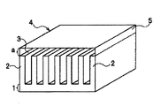
図2、3は、それぞれ本発明の自然空冷用ヒートシンク100を筐体内に配置した状態の一例を示す側面図、及び正面図(図2におけるI−I´断面図)である。図2に示すように、筐体30の内部には、様々な部材を実装する基板32、及び基板32上に実装された発熱素子34が配置されている。本発明の自然空冷用ヒートシンク100は、ベースプレート10の一方の面が発熱素子34に熱的に接続され、かつ、ベースプレート10又はフィン20に設けられた図示しない固定方法によって基板32に固定されている。
2 and 3 are a side view and a front view (a cross-sectional view taken along the line II ′ in FIG. 2) showing an example of a state in which the natural air
フィン20は、ベースプレート10に熱的に接続される受熱部27と、該受熱部27から略垂直に立ち上がる放熱部29を備えており、横断面が略L字形状となっている。このようなフィン20をベースプレート10上に複数立設することによって放熱部を形成している。
The fin 20 includes a
また、図3に示すように、フィン20は、上端部23の近傍に切欠き部25を備えている。図2及び図3の複数の矢印A1〜A4は、自然空冷用ヒートシンク100の周囲の空気の流れを示している。
As shown in FIG. 3, the
ここで、ヒートシンク内の熱の移動について説明する。まず、発熱素子34の熱は、ベースプレート10に移動し、ベースプレート10の面内全体に拡散する。次にベースプレート10に移動した熱は、ベースプレート10に熱的に接続されたフィン20の受熱部27に移動し、さらに、放熱部29へ移動することで、自然空冷用ヒートシンク100の上方へ移動する。
Here, the movement of heat in the heat sink will be described. First, the heat of the
次に、自然空冷用ヒートシンク100の周囲の空気の流れについて説明する。図2に示すように、自然空冷用ヒートシンク100のベースプレート10近傍で暖められた空気は、隣接するフィン20間を上方へ移動する(A1)。このとき、空気は、フィン20間を移動しながら、フィン20の放熱部29の熱によっても暖められる。
Next, the flow of air around the natural air
自然空冷用ヒートシンク100の上部まで移動した空気の一部は、フィン20の上端部23の近傍に設けられた切欠き部25を通って、フィン20の放熱部29に対して垂直な方向に移動することが可能となっている(A2)。また、ヒートシンク100の上部まで移動した空気の他の一部は、図3に示すように、フィン20の放熱部29の面方向に移動し、自然空冷用ヒートシンク100の外側へ抜ける(A3)。
Part of the air that has moved to the top of the natural air
上記A1〜A3の空気の流れに伴って、自然空冷用ヒートシンク100の下側方から筐体内の空気が導入される(A4)。自然空冷用ヒートシンク100の周囲において、A1〜A4の空気の流れが循環することによって、発熱素子34の熱を効率よく、筐体30内の空気へ放散することができる。
ここで、本発明の自然空冷用ヒートシンク100は、切欠き部25を備えているため、ヒートシンク100の上部へ移動した空気が滞留することなく、フィン20の放熱部29に対して垂直な方向に移動するため、空気の循環が一層促進され、効率的な放熱が可能となる。
Along with the air flows A1 to A3, the air in the housing is introduced from the lower side of the natural air cooling heat sink 100 (A4). The air flows A1 to A4 circulate around the natural air
Here, since the natural air
切り欠き部25が無い場合、ヒートシンク100の下側方から導入される空気(A4)のほとんどはフィン20の上側方から外にでていく(A3)。このため、フィン20の中央(発熱素子34に対応する部分)の気流(A1)の流速は小さく、フィン20の上側方の気流(A3)の流速は大きくなる。放熱効率を向上させるために、切り欠き部25をフィン20の上端部23の中央に設置して、フィン20の中央の気流(A1)、およびフィン20の上端部23を通る気流(A2)を促進する。
When there is no
切り欠き部25は、発熱素子34に対応するフィン20の上端部23に設ければよい。フィン20の上端部23の側方(発熱素子34に対応する部分以外)に設置すると、もともと流速が大きく熱伝達の効率が大きい側方の空気(A3)と放熱部29との接触面積が減少するため、ヒートシンク100全体の性能は低下してしまうおそれがあるため、好ましくない。
The
次に、本発明の自然空冷用ヒートシンクに用いられるフィンについて詳細に説明する。図4は、本発明に用いられるフィンの別の態様を示す斜視図である。図4に示すように、このフィン20Aは、図1に示すフィン20の構成に加え、切欠き部25に対応する形状の切り起し部25aを備えている。
Next, the fin used for the natural air cooling heat sink of the present invention will be described in detail. FIG. 4 is a perspective view showing another embodiment of the fin used in the present invention. As illustrated in FIG. 4, the
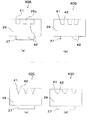
このようなフィンの製造方法については、特に限定されないが、例えば、図5(a)に示すように、受熱部27、放熱部29に対応した形状の金属板材40Aを調製する。該金属板材40Aには、放熱部29の所定の位置に切欠き部25に対応した切り込み41が形成される。その後、プレス等によって受熱部27、及び切り起し片25bを曲げ部42に沿って、放熱部29に対して略直角となるように曲げ加工されることによって本発明の自然空冷用ヒートシンクに用いられるフィンを形成することができる。
Although the manufacturing method of such a fin is not specifically limited, For example, as shown to Fig.5 (a), the
ここで、切り起し片25bの形状としては、図5(a)〜(d)に示すような、四角形、台形、三角形、円弧形などが望ましい。ここで、切り起し部25aは、上述した空気の流れA1〜A3に沿って形成されることが望ましい。
Here, as the shape of the cut and raised
このような構成とすることで、フィン20Aの放熱部29の面積を減少させることなく、ヒートシンクの周囲の空気を効果的に循環させることができるため、より効率良く放熱することが可能となる。
With such a configuration, the air around the heat sink can be circulated effectively without reducing the area of the
(第2の実施形態)
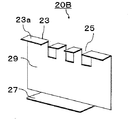
図6は、本発明の第2の実施形態に係る自然空冷用ヒートシンク200を示す斜視図である。図6に示すように、この自然空冷用ヒートシンク200に用いられるフィン20Bは、図4に示すフィン20Aの構成に加え、上端部23から、受熱部27に対して水平に延伸し、図示しない筐体と熱的に接続される第2の放熱部23aを備えている。第2の放熱部23aは、隣接する他のフィンの第2の放熱部23aと接続され、放熱面を形成している。
(Second Embodiment)
FIG. 6 is a perspective view showing a natural air
図7は、本発明の第2の実施形態に係る自然空冷用ヒートシンク200を筐体内に配置した一例を示す側面図である。図7に示すように、自然空冷用ヒートシンク200は、ベースプレート10の一方の面が発熱素子34に熱的に接続され、かつ、ベースプレート10又はフィン20Bに設けられた図示しない固定方法によって基板32に固定されている
また、第2の放熱部23aによって形成された放熱面がTIM(Thermal Interface Material)36を介して、筐体に熱的に接続されている。
FIG. 7 is a side view showing an example in which a natural air
本発明の第2の実施形態によれば、自然空冷用ヒートシンク200の上端部23に形成された第2の放熱部23aと、筐体30とが熱的に接続されているため、発熱素子34の熱を筐体30を介して放散することができるため、さらに放熱効率を向上させることができる。
According to the second embodiment of the present invention, since the second
本発明の第2の実施形態に用いられるTIMとしては、所定の厚さを有する伝熱シート、熱伝導性グリース等を用いることができる。伝熱シートを用いる場合、その厚さは熱伝導性を良好に保つために、0.2mm以上、1.0mm以下が好ましい。 As the TIM used in the second embodiment of the present invention, a heat transfer sheet, a heat conductive grease, or the like having a predetermined thickness can be used. In the case of using a heat transfer sheet, the thickness is preferably 0.2 mm or more and 1.0 mm or less in order to maintain good heat conductivity.
図8は、本発明の第2の実施形態に係る自然空冷用ヒートシンクに用いられるフィン20Bの一の態様を示す斜視図である。図8に示すように、フィン20Bは、図示しないベースプレートに熱的に接続される受熱部27と、該受熱部27から略垂直に立ち上がる放熱部(第1の放熱部)29を備えている。さらに、フィン20Bは、上端部23から、受熱部27に対して水平に延伸する第2の放熱部23aを備えている。
FIG. 8 is a perspective view showing one aspect of the
第2の放熱部23aは、第1の放熱部29に対して、受熱部27と同じ方向に延伸していてもよく、逆方向に延伸していてもよい。
第2の放熱部23aが、第1の放熱部29に対して、受熱部27と同じ方向に延伸している場合、断面は略コの字型となっている。
The second
When the second
このようなフィン20Bをベースプレート上に複数並列に立設することによって、図6に示すように、ベースプレート及び筐体に熱的に接続されるヒートシンクを形成することができる。
By installing a plurality of
図9は、本発明の第2の実施形態に係る自然空冷用ヒートシンクに用いられるフィンの別の態様を示す側面図である。図9に示すように、フィン20Cは、第1の放熱部29に凸部(又は凹部)29aを設け、この部分の弾性変形により受熱部27と第2の放熱部23aの間にかかる応力を緩和するようにしている。凸部(又は凹部)29aの形状としては、所定の弾性力を備えていれば特に制限はなく、断面がコの字、三角、半円形等、様々な形を採用することができる。また、弾性変形する部分は、1箇所以上設けていればよく、複数設けていても良い。
FIG. 9: is a side view which shows another aspect of the fin used for the heat sink for natural air cooling which concerns on the 2nd Embodiment of this invention. As shown in FIG. 9, the
100、200 自然冷却用ヒートシンク
10 ベースプレート
20、20A〜C フィン
23 (フィンの)上端部
23a 第2の放熱部
25 切欠き部
25a 切り起し部
25b 切り起し片
27 受熱部
29 放熱部(第1の放熱部)
29a 凸部(又は凹部)
30 筐体
32 基板
34 発熱素子
36 TIM
40A〜D 金属板材
41 切り込み
42 曲げ部
100, 200 Natural
29a Convex part (or concave part)
30
40A-D
Claims (6)
一方の面が発熱素子に熱的に接続されるベースプレートと、
その下端部が、前記ベースプレートの他方の面に熱的に接続された複数のフィンからなる放熱フィン部とを備え、
前記フィンは、前記発熱素子に対応する部分の上端部近傍に一つ以上の切欠き部を有することを特徴とする自然空冷用ヒートシンク。 A heat sink for natural air cooling for cooling a heating element in a housing,
A base plate having one surface thermally connected to the heating element;
The lower end portion includes a heat dissipating fin portion composed of a plurality of fins thermally connected to the other surface of the base plate,
The natural air cooling heat sink, wherein the fin has one or more notches in the vicinity of an upper end of a portion corresponding to the heating element.
前記一の辺は、前記上辺に隣接する辺のいずれか一方であることを特徴とする請求項1または2に記載の自然空冷用ヒートシンク。 The notch has a rectangular shape with the upper side of the fin as one side,
The natural air cooling heat sink according to claim 1, wherein the one side is one of sides adjacent to the upper side.
前記受熱部から立ち上がる放熱部とを備えた断面略L字形状の金属薄板であることを特徴とする請求項1乃至請求項3のいずれか1項に記載の自然空冷用ヒートシンク。 The fin is a heat receiving portion thermally connected to the base plate;
The natural air cooling heat sink according to any one of claims 1 to 3, wherein the heat sink is a thin metal plate having a substantially L-shaped cross section including a heat radiating portion rising from the heat receiving portion.
前記受熱部から立ち上がる第1放熱部と、
前記フィンの上辺近傍に形成され前記筐体に熱的に接続される第2放熱部とを備えた断面略コの字形状の金属薄板であることを特徴とする請求項1乃至請求項3のいずれか1項に記載の自然空冷用ヒートシンク。 The fin is a heat receiving portion thermally connected to the base plate;
A first heat dissipating part rising from the heat receiving part;
4. The thin metal plate having a substantially U-shaped cross section provided with a second heat radiating portion formed in the vicinity of the upper side of the fin and thermally connected to the housing. The heat sink for natural air cooling according to any one of the items.
Priority Applications (1)
| Application Number | Priority Date | Filing Date | Title |
|---|---|---|---|
| JP2009060571A JP2010219085A (en) | 2009-03-13 | 2009-03-13 | Heat sink for natural air cooling |
Applications Claiming Priority (1)
| Application Number | Priority Date | Filing Date | Title |
|---|---|---|---|
| JP2009060571A JP2010219085A (en) | 2009-03-13 | 2009-03-13 | Heat sink for natural air cooling |
Publications (1)
| Publication Number | Publication Date |
|---|---|
| JP2010219085A true JP2010219085A (en) | 2010-09-30 |
Family
ID=42977647
Family Applications (1)
| Application Number | Title | Priority Date | Filing Date |
|---|---|---|---|
| JP2009060571A Pending JP2010219085A (en) | 2009-03-13 | 2009-03-13 | Heat sink for natural air cooling |
Country Status (1)
| Country | Link |
|---|---|
| JP (1) | JP2010219085A (en) |
Cited By (5)
| Publication number | Priority date | Publication date | Assignee | Title |
|---|---|---|---|---|
| JP2013101192A (en) * | 2011-11-07 | 2013-05-23 | Altair Giken Kk | Culture apparatus for microscope |
| JP2013226297A (en) * | 2012-04-26 | 2013-11-07 | Sankyo Co Ltd | Game machine |
| CN113611678A (en) * | 2021-08-30 | 2021-11-05 | 江西江南精密科技有限公司 | Efficient and precise heat dissipation copper block and manufacturing process |
| TWI787712B (en) * | 2021-01-20 | 2022-12-21 | 立端科技股份有限公司 | Heat dissipation device (heat sink) with notch structure |
| CN116466520A (en) * | 2023-04-27 | 2023-07-21 | 惠科股份有限公司 | Lampshade, backlight module and display device |
Citations (5)
| Publication number | Priority date | Publication date | Assignee | Title |
|---|---|---|---|---|
| JPS57188854A (en) * | 1981-04-21 | 1982-11-19 | Kobe Steel Ltd | Manufacture of radiator for semiconductor element |
| JPS59146959U (en) * | 1983-03-23 | 1984-10-01 | 東京ラヂエ−タ−製造株式会社 | air cooled radiator |
| JP3091858U (en) * | 2002-08-02 | 2003-02-21 | 華▲孚▼科技股▲ふん▼有限公司 | Combination structure of heat dissipation device |
| JP2008066641A (en) * | 2006-09-11 | 2008-03-21 | Sony Computer Entertainment Inc | Electronic apparatus and heatsink |
| JP3146845U (en) * | 2008-09-19 | 2008-12-04 | 奇▲こう▼科技股▲ふん▼有限公司 | Electronic equipment cooling radiator |
-
2009
- 2009-03-13 JP JP2009060571A patent/JP2010219085A/en active Pending
Patent Citations (5)
| Publication number | Priority date | Publication date | Assignee | Title |
|---|---|---|---|---|
| JPS57188854A (en) * | 1981-04-21 | 1982-11-19 | Kobe Steel Ltd | Manufacture of radiator for semiconductor element |
| JPS59146959U (en) * | 1983-03-23 | 1984-10-01 | 東京ラヂエ−タ−製造株式会社 | air cooled radiator |
| JP3091858U (en) * | 2002-08-02 | 2003-02-21 | 華▲孚▼科技股▲ふん▼有限公司 | Combination structure of heat dissipation device |
| JP2008066641A (en) * | 2006-09-11 | 2008-03-21 | Sony Computer Entertainment Inc | Electronic apparatus and heatsink |
| JP3146845U (en) * | 2008-09-19 | 2008-12-04 | 奇▲こう▼科技股▲ふん▼有限公司 | Electronic equipment cooling radiator |
Cited By (6)
| Publication number | Priority date | Publication date | Assignee | Title |
|---|---|---|---|---|
| JP2013101192A (en) * | 2011-11-07 | 2013-05-23 | Altair Giken Kk | Culture apparatus for microscope |
| JP2013226297A (en) * | 2012-04-26 | 2013-11-07 | Sankyo Co Ltd | Game machine |
| TWI787712B (en) * | 2021-01-20 | 2022-12-21 | 立端科技股份有限公司 | Heat dissipation device (heat sink) with notch structure |
| CN113611678A (en) * | 2021-08-30 | 2021-11-05 | 江西江南精密科技有限公司 | Efficient and precise heat dissipation copper block and manufacturing process |
| CN116466520A (en) * | 2023-04-27 | 2023-07-21 | 惠科股份有限公司 | Lampshade, backlight module and display device |
| CN116466520B (en) * | 2023-04-27 | 2025-10-03 | 惠科股份有限公司 | Lampshade, backlight module and display device |
Similar Documents
| Publication | Publication Date | Title |
|---|---|---|
| JP5537777B2 (en) | Heat sink, cooling module and coolable electronic board | |
| CN203085512U (en) | Servo amplifier | |
| JP3854920B2 (en) | Heat dissipation structure of electronic equipment | |
| JP5335839B2 (en) | Power conversion module heat dissipation device | |
| KR20120074245A (en) | Cooling apparatus and power converter having the same | |
| JP2014204606A (en) | Electric power conversion apparatus and cooling fin | |
| JP2016178208A (en) | Heat sink, heat dissipation structure, cooling structure and device | |
| KR200467728Y1 (en) | Heat dissipation device with multiple heat conducting pipes | |
| JP2010219085A (en) | Heat sink for natural air cooling | |
| JP2010267912A (en) | Cooling system | |
| JP2003100974A (en) | Air-cooling semiconductor heat sink | |
| JP3665508B2 (en) | Heat sink with fins | |
| CN209398636U (en) | Fan | |
| JP2014093338A (en) | Cooling fin | |
| JP5705570B2 (en) | Electronic component cooling system | |
| JP6883498B2 (en) | Heatsink | |
| JP4723661B2 (en) | Heat receiving surface parallel fin type flat heat dissipation structure | |
| JP2010087016A (en) | Heat sink for natural air cooling | |
| JP2004071635A (en) | Tower heat sink | |
| JP4969979B2 (en) | heatsink | |
| JP3096855U (en) | Heat dissipation module | |
| JP4002249B2 (en) | Heat dissipation device cooling heat dissipation device | |
| JP5400690B2 (en) | heatsink | |
| KR20100109071A (en) | Radient heat apparatus and method for manufacturing the same | |
| JP3081986U (en) | Heat dissipation structure of central processing unit |
Legal Events
| Date | Code | Title | Description |
|---|---|---|---|
| A621 | Written request for application examination |
Effective date: 20111201 Free format text: JAPANESE INTERMEDIATE CODE: A621 |
|
| A977 | Report on retrieval |
Free format text: JAPANESE INTERMEDIATE CODE: A971007 Effective date: 20121108 |
|
| A131 | Notification of reasons for refusal |
Effective date: 20121113 Free format text: JAPANESE INTERMEDIATE CODE: A131 |
|
| A02 | Decision of refusal |
Effective date: 20130308 Free format text: JAPANESE INTERMEDIATE CODE: A02 |