JP2010222012A - Table top mounting type sealing device for packaging container - Google Patents
Table top mounting type sealing device for packaging container Download PDFInfo
- Publication number
- JP2010222012A JP2010222012A JP2009068495A JP2009068495A JP2010222012A JP 2010222012 A JP2010222012 A JP 2010222012A JP 2009068495 A JP2009068495 A JP 2009068495A JP 2009068495 A JP2009068495 A JP 2009068495A JP 2010222012 A JP2010222012 A JP 2010222012A
- Authority
- JP
- Japan
- Prior art keywords
- container
- conveyor
- sealing
- side frame
- adhesive tape
- Prior art date
- Legal status (The legal status is an assumption and is not a legal conclusion. Google has not performed a legal analysis and makes no representation as to the accuracy of the status listed.)
- Pending
Links
- 238000007789 sealing Methods 0.000 title claims abstract description 93
- 238000004806 packaging method and process Methods 0.000 title claims description 23
- 230000007246 mechanism Effects 0.000 claims abstract description 53
- 230000002093 peripheral effect Effects 0.000 claims abstract description 28
- 230000003028 elevating effect Effects 0.000 claims abstract description 9
- 230000001360 synchronised effect Effects 0.000 claims abstract description 5
- 239000002390 adhesive tape Substances 0.000 claims description 26
- 238000005520 cutting process Methods 0.000 claims description 19
- 238000012546 transfer Methods 0.000 claims description 11
- 229920003002 synthetic resin Polymers 0.000 claims description 10
- 239000000057 synthetic resin Substances 0.000 claims description 10
- 239000000463 material Substances 0.000 claims description 9
- 238000006116 polymerization reaction Methods 0.000 claims description 7
- 230000005540 biological transmission Effects 0.000 claims description 4
- 238000005452 bending Methods 0.000 claims description 3
- 239000004820 Pressure-sensitive adhesive Substances 0.000 abstract description 8
- 235000013601 eggs Nutrition 0.000 description 10
- 239000000758 substrate Substances 0.000 description 7
- 235000013305 food Nutrition 0.000 description 5
- 235000013311 vegetables Nutrition 0.000 description 5
- 235000009508 confectionery Nutrition 0.000 description 4
- 238000003825 pressing Methods 0.000 description 4
- 235000014676 Phragmites communis Nutrition 0.000 description 3
- 235000013399 edible fruits Nutrition 0.000 description 3
- 235000009434 Actinidia chinensis Nutrition 0.000 description 2
- 244000298697 Actinidia deliciosa Species 0.000 description 2
- 235000009436 Actinidia deliciosa Nutrition 0.000 description 2
- 241000251468 Actinopterygii Species 0.000 description 2
- 241000227653 Lycopersicon Species 0.000 description 2
- 235000007688 Lycopersicon esculentum Nutrition 0.000 description 2
- 230000008901 benefit Effects 0.000 description 2
- 210000000991 chicken egg Anatomy 0.000 description 2
- 235000021186 dishes Nutrition 0.000 description 2
- 230000000694 effects Effects 0.000 description 2
- 238000000034 method Methods 0.000 description 2
- 230000000149 penetrating effect Effects 0.000 description 2
- 235000012046 side dish Nutrition 0.000 description 2
- 241000219310 Beta vulgaris subsp. vulgaris Species 0.000 description 1
- 229920000298 Cellophane Polymers 0.000 description 1
- 244000175448 Citrus madurensis Species 0.000 description 1
- 235000017317 Fortunella Nutrition 0.000 description 1
- 241000287828 Gallus gallus Species 0.000 description 1
- 125000002066 L-histidyl group Chemical group [H]N1C([H])=NC(C([H])([H])[C@](C(=O)[*])([H])N([H])[H])=C1[H] 0.000 description 1
- 235000021536 Sugar beet Nutrition 0.000 description 1
- 230000009471 action Effects 0.000 description 1
- 239000000853 adhesive Substances 0.000 description 1
- 230000001070 adhesive effect Effects 0.000 description 1
- 235000008429 bread Nutrition 0.000 description 1
- 230000008859 change Effects 0.000 description 1
- 230000008602 contraction Effects 0.000 description 1
- 239000006260 foam Substances 0.000 description 1
- 235000012055 fruits and vegetables Nutrition 0.000 description 1
- 230000005484 gravity Effects 0.000 description 1
- 238000004519 manufacturing process Methods 0.000 description 1
- 235000013372 meat Nutrition 0.000 description 1
- 238000012986 modification Methods 0.000 description 1
- 230000004048 modification Effects 0.000 description 1
- 238000012856 packing Methods 0.000 description 1
- 229920000642 polymer Polymers 0.000 description 1
- 238000012545 processing Methods 0.000 description 1
Images





Landscapes
- Package Closures (AREA)
- Closing Of Containers (AREA)
Abstract
Description
本発明は、例えば天ぷらや煮物野菜、煮物魚肉類その他の加工惣菜類の包装用容器や、鶏卵包装用の容器、キウイ・キンカン・イチジク・トマト等その他の果菜類、菓子・パンのような食品包装用の容器として使用されている主として合成樹脂シート材製の包装用容器を、内部に所要食品類を収容して封緘するときに、容器の周縁部を粘着テープによって封緘するために使用する装置に関するものである。 The present invention includes, for example, packaging containers for tempura, boiled vegetables, boiled fish meats and other processed vegetables, chicken egg packaging containers, other fruit vegetables such as kiwi, kumquat, figs and tomatoes, foods such as confectionery and bread A device used to seal the peripheral part of a container with an adhesive tape when a packaging container mainly made of a synthetic resin sheet used as a packaging container is sealed with necessary foods contained therein. It is about.
殊に、スーパーマーケットやコンビニエンスストア、青果店・鮮魚店・和洋菓子店等の食品包装場所や店頭に載置して、惣菜その他の商品を収容して商品包装担当者がその場で封緘したり、場合によっては、店頭で商品を購入した購買客自身が商品を収容した容器を封緘することができるように小型化した卓上載置型の封緘装置に関するものである。 Especially, it is placed in food packaging places and stores such as supermarkets, convenience stores, fruit and vegetable stores, fresh fish stores, Japanese and Western confectionery stores, etc. In some cases, the present invention relates to a desktop-type sealing device that is downsized so that a customer who has purchased the product at the store can seal the container that stores the product.
従来から、容器本体と蓋体とをその一側においてヒンジ部を介して一体的に連結されている合成樹脂シート材製の包装用容器や、容器本体と蓋体とを別々に形成してある合成樹脂シート材製の包装用容器が知られている。これらの容器内に所要の商品を収容させた後その周縁部が適宜の手段でシールされている。この包装形態としては、その多くの場合は収容商品の生産工場内等において効率的に行われている。例えば鶏卵包装用容器の場合、複数の鶏卵を容器内に収容し、蓋を閉じて容器本体と蓋体との重ね合わせ周縁部を粘着テープで工業的に封緘することが鶏卵生産者において行われている。この鶏卵包装用の自動封緘装置は、例えば本特許出願人が既に提案し公知になっている。このことは、後記の特許文献1や2に記載されている通りである。
Conventionally, a packaging container made of a synthetic resin sheet material in which a container main body and a lid are integrally connected via a hinge portion on one side thereof, and a container main body and a lid are formed separately. A packaging container made of a synthetic resin sheet material is known. After a required product is accommodated in these containers, the peripheral edge thereof is sealed by appropriate means. In many cases, the packaging is efficiently performed in a production factory for stored goods. For example, in the case of a container for egg wrapping, a plurality of eggs are accommodated in the container, the lid is closed, and the overlapping peripheral portion of the container body and the lid body is industrially sealed with adhesive tape in the egg producer. ing. Such an automatic sealing device for wrapping eggs has already been proposed and publicly known by, for example, the present applicant. This is as described in
このように、現在使用されている鶏卵包装用容器の封緘装置は、鶏卵生産者が自社に設置した一連の鶏卵自動梱包ラインの末端部分に配置して、例えば1分間に50個〜60個またはそれ以上の容器を自動的に封緘する自動機によって封緘されている。自動封緘機で封緘された鶏卵は段ボール箱等に収容され梱包されたのち、市場に出荷され、店頭に陳列されている。 Thus, the egg-sealing container sealing device currently used is arranged at the end of a series of automatic egg-packing lines installed by an egg producer in its own company, for example, 50-60 pieces per minute or It is sealed by an automatic machine that automatically seals any further containers. Eggs sealed by an automatic sealing machine are stored in a cardboard box and packed, then shipped to the market and displayed at the store.
しかしながら、鶏卵についてみれば、一人暮らしの年配者のみならず、若者であっても一人暮らしの人々にとっては、10個包装の鶏卵ではなく、ばら売りの鶏卵を1個若しくは2、3個必要量だけ購入したいという要求があり、また、近年では、このような単身生活者に限らず一般家庭人にあっても、前記のように、天ぷらや煮物類等の惣菜類や、キウイやトマトその他の小形の果菜類等を、購買者の好みに応じて必要量を購入し、購買者自身が合成樹脂シート材製の容器に入れて持ち帰るというケースが見られるようになってきている。このような場合、現在では、容器を封緘する手段として店頭に用意されている輪ゴムを掛けるのが一般的で、時にはセロファンテープで仮止めすることも行われている。しかしながら、これらの封緘手段は密閉効果が悪く、持ち運び中に容易に蓋が開いてしまうという解決すべき課題を有しているが、このような封緘方法に代わる方法は現在のところ未だ存在しない。 However, with regard to eggs, not only elderly people living alone, but also young people living alone, purchase only one, two, or three pieces of eggs that are sold separately instead of 10 eggs. In recent years, not only singles but also ordinary households, as mentioned above, side dishes such as tempura and boiled dishes, kiwi, tomatoes and other small-sized dishes In some cases, fruit vegetables and the like are purchased in a required amount according to the preference of the purchaser, and the purchaser himself puts it in a container made of a synthetic resin sheet material and takes it home. In such a case, at present, it is common to hang a rubber band prepared at the store as a means for sealing the container, and sometimes it is temporarily fixed with cellophane tape. However, these sealing means have a poor sealing effect and have a problem to be solved that the lid easily opens during carrying. However, there is not yet a method for replacing such a sealing method.
本発明は、このような課題を解消するための手段として開発されたもので、軽量かつ小型で店舗内の調理場や店頭の卓上や台上に載置して使用することができるように小型化した封緘機であって、通常の100V電源を使用して、店の従業員のみならず、商品の購買者自身でも容易簡単に封緘できる容器の封緘装置を提供しようとするものである。 The present invention has been developed as a means for solving such problems, and is light and small in size so that it can be used by being placed on a kitchen or a tabletop or table in a store. The present invention aims to provide a container sealing device that can be easily and easily sealed not only by store employees but also by merchandise purchasers themselves using a normal 100V power supply.
該目的を達成するために本発明では前記請求項1に記載のような技術的手段を講じた。即ち、本発明に係る包装用容器の卓上載置型封緘装置の主たる構成を、実施例説明に使用した図面の符号を用いて説明すると、容器本体と蓋体とからなる合成樹脂シート材製包装用容器Cの閉蓋姿勢で重合する周縁部を粘着テープで封緘する卓上載置型の封緘装置であって、物品を収容させて閉蓋姿勢とした容器を移動させるコンベア5を備えたコンベア側枠体Aと、閉蓋姿勢とした前記容器Cの重合周縁部4を粘着テープ6で封緘する封緘機構7を備えた封緘側枠体Bと、前記コンベア5を所定の方向に駆動させるモータMと、該モータMの回転をコンベア5に伝達する回転伝達体とを備え、前記コンベア側枠体Aと封緘側枠体Bとが互いに独立体として形成され、これら両枠体A,Bの少なくとも一方が昇降移動機構Dを備え、この昇降移動機構Dがコンベア側枠体Aに装着されている場合はコンベア5の容器移送面を昇降させ、封緘側枠体Bに装着されている場合は封緘機構7の後記一対の圧着ローラ間を昇降させる構成とされ、前記封緘機構7は、前記粘着テープ6を断面V字形に屈曲させながら圧着ローラに向けて送り込むガイド部材14と、該ガイド部材14から送り込まれた粘着テープ6を容器の重合周縁部4に二つ折り状として接着させる上下一対の圧着ローラ10,10とを備え、これら両枠体A,Bの何れか一方に、封緘済み容器の移動方向後端側に連なる粘着テープの切断刃体81を備えたカッター機構8が配置され、該カッター機構8の切断刃体81が、常時はテープ非切断箇所に待避していて、容器の存否を検知する光電管やリミットスイッチ等の関知機構の関知作用によってテープ切断位置へ移動し、この移動に伴ってテープを切断する構造とされ、かつ、前記圧着ローラ10,10のテープ送り速度とコンベア5の容器送り速度とが同期するように連動連結されている構成としたものである。
In order to achieve the object, the present invention takes technical means as described in the first aspect. That is, the main structure of the tabletop sealing device for packaging containers according to the present invention will be described using the reference numerals of the drawings used for the description of the embodiments. For packaging made of a synthetic resin sheet material comprising a container body and a lid. A table-top-type sealing device that seals a peripheral portion of the container C that is polymerized in a closed posture with an adhesive tape, and includes a
また、請求項2に記載の要件は、請求項1に記載の装置における昇降移動機構Dが、コンベア側枠体Aに装着されていて、コンベア5の容器移送面を昇降させ、容器の重合周縁部4の高さ位置を封緘側枠体Bにおける上下一対の圧着ローラ10,10間の高さに合わせる構造とした構成にある。
In addition, the requirement described in
続く請求項3に記載の要件は、請求項1に記載の装置における昇降移動機構Dが、封緘側枠体Bに装着されていて、上下一対の圧着ローラ10,10間の高さ位置を昇降させ、該圧着ローラ10,10間の高さ位置をコンベア5の容器移送面上を移動する容器の重合周縁部4の高さ位置に合わせる構造とした構成にある。
The subsequent claim 3 is that the lifting / lowering movement mechanism D in the apparatus according to
本発明にいうところの卓上載置型封緘装置は、上記のように、軽量かつ小型に形成し、店舗内の調理場や店頭の卓上や台上の小さな空間に載置して使用することができるように小型化した封緘機であって、一般の建物内のどこにでも存在する100V電源のコンセントにモータの電源コード端のプラグを差し込むだけで、直ちにコンベアを所定の方向に駆動させて使用することができ、コンベア上に載置した容器の重合周縁部を上下一対の圧着ローラ間に移行させて通過させることにより、容器の周縁部を粘着テープで挟み込ませながら封緘することができるのである。殊に、封緘機構における圧着ローラのテープ送り速度とコンベアの容器送り速度とを同期するようにそれぞれの駆動部を連動連結させてあるので、粘着テープによる容器の封緘を常に確実に行うことができる。 As described above, the tabletop sealing device according to the present invention is light and small in size, and can be used by being placed in a small space on a kitchen or storetop in a store or in a store. The sealer is miniaturized as described above, and is used by immediately driving the conveyor in a predetermined direction just by inserting the plug of the motor power cord end into a 100V power outlet present anywhere in a general building. It is possible to seal the container while the peripheral part of the container is sandwiched between adhesive tapes by allowing the peripheral part of the container placed on the conveyor to pass between the pair of upper and lower pressure rollers. In particular, since each drive unit is interlocked and connected so as to synchronize the tape feeding speed of the pressure roller in the sealing mechanism and the container feeding speed of the conveyor, it is possible to always reliably seal the container with the adhesive tape. .
また、封緘装置をコンベア側枠体と封緘側枠体とに分割し、これらの枠体を互いに独立体として形成してあることにより、容器のサイズや形が異なって封緘する周縁部の高さが異なるものであっても、即ち、容器の底面からの重合周縁部の高さが異なる容器の場合でも、コンベアに対する封緘機構の高さ位置や、封緘機構に対するコンベアの高さ位置を高低操作して高さ調整できるようにしてあるので、各種の容器に適応させることができる利点がある。更には、装置全体を卓上や小形の台上に載置させて操作できるように小型で軽量なものに形成してあるので、持ち運びが容易にでき、場所をとらないため、店頭の適宜の箇所に載置して使用でき、購買者自身でも容器内に好みに応じた商品を収容させ、該容器を封緘するにあたり便利に使用できるという効果がある。 Also, by dividing the sealing device into a conveyor side frame and a sealing side frame, and forming these frames as independent bodies, the height of the peripheral edge that seals differently in size and shape of the container Even when the height of the overlapping peripheral part from the bottom of the container is different, the height position of the sealing mechanism relative to the conveyor and the height position of the conveyor relative to the sealing mechanism are manipulated. Therefore, there is an advantage that it can be adapted to various containers. Furthermore, since the entire device can be placed on a tabletop or small table and operated so that it is small and lightweight, it is easy to carry and saves space. There is an effect that the purchaser himself / herself can use the product according to his / her preference in the container and can be conveniently used for sealing the container.
本発明の実施に当たっては、前記請求項2に記載の封緘装置のように、昇降移動機構がコンベア側枠体Aに装着されているものとして、コンベアの容器移送面を昇降させ、容器の重合周縁部の高さ位置を封緘側枠体Bにおける上下一対の圧着ローラ間の高さに合わせて調節する構造とし、重合周縁部の高さが異なる各種の容器に対応させて実施することができる。
In carrying out the present invention, as in the sealing device according to
また、本発明の実施に当たって前記請求項3に記載の封緘装置のように、昇降移動機構が封緘側枠体Bに装着されているものとし、上下一対の圧着ローラ間の高さ位置を昇降調節させてコンベア上に載置させた容器の重合周縁部の高さ位置と合致するようにして、重合周縁部の高さの異なる各種の容器に対応させて実施することもできる。 In carrying out the present invention, as in the sealing device according to claim 3, it is assumed that the lifting / lowering moving mechanism is mounted on the sealing-side frame B, and the height position between the pair of upper and lower pressure-bonding rollers is adjusted up and down. It can also be carried out corresponding to various containers having different heights of the polymerization peripheral edge so as to coincide with the height position of the polymerization peripheral edge of the container placed on the conveyor.
粘着テープを断面V字形に屈曲させながら圧着ローラに向けて送り込むガイド部材と、このテープを受け取る圧着ローラとは、なるべく接近させて配置しておくと、断面V字形としたテープを容器の重合周縁部に対して確実に接着させ易い点で好ましい。このようにしておけば、容器の重合周縁部の外端縁を、ガイド部材に形成された断面V字形の屈曲部分に粘着テープを介して当てつけながら、隣接する圧着ローラ間に距離を置くことなく直ちに送り込むことができるので、断面V字形に形成された粘着テープの屈曲部分に容器の重合周縁部の外端縁を当てつけた状態で圧着ローラによってテープが圧着され、容器の重合周縁部に対するテープの確実な押圧接合を行うことができるという利点がある。 The guide member that feeds the adhesive tape toward the pressure roller while bending it in a V-shaped cross section and the pressure roller that receives the tape are arranged as close as possible. It is preferable in that it can be reliably adhered to the part. If it does in this way, without putting the distance between the adjoining press rollers, applying the outer edge of the overlapping peripheral portion of the container to the bent portion of the V-shaped cross section formed on the guide member via the adhesive tape Since the tape can be fed immediately, the tape is pressure-bonded by the pressure roller with the outer edge of the overlapping edge of the container being in contact with the bent portion of the adhesive tape formed in a V-shaped cross section, and the tape against the overlapping edge of the container There is an advantage that reliable press bonding can be performed.
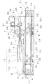
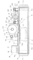
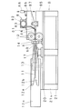
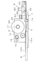
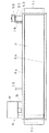
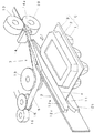
以下本発明に係る包装用容器の卓上載置型封緘装置に関する第1実施例を図面に基づいて説明する。図1乃至図8は、該第1実施例を示す図であって、図1はその全体形状を示す正面図、図2は同平面図、図3及び図5は封緘側枠体の正面図と平面図、図4及び図6はコンベア側枠体の正面図と平面図、図7は封緘機構部分を示す斜視図、図8はカム操作による昇降操作を説明する斜視図である。 A first embodiment relating to a tabletop sealing device for packaging containers according to the present invention will be described below with reference to the drawings. 1 to 8 are views showing the first embodiment, in which FIG. 1 is a front view showing the overall shape thereof, FIG. 2 is a plan view thereof, and FIGS. 3 and 5 are front views of a sealed side frame. 4 and 6 are a front view and a plan view of the conveyor-side frame, FIG. 7 is a perspective view showing a sealing mechanism portion, and FIG. 8 is a perspective view for explaining a lifting operation by a cam operation.
該実施例に示した卓上載置型封緘装置は、図1、2のように装置の全体を任意のテーブルや台上に載置して操作できるように小型サイズに形成してある。その大きさは必ずしも特定の大きさの範囲内のものでなければならないものではないが、該実施例に示した装置全体の大きさを参考までに記載しておくと次の大きさ程度のものである。図1における左右方向の長さは500〜600mmであり、高さは180〜250mmである。また、使用する粘着テープの幅についても特に限定されるものではなく、敢えて記載すると、9mm、10mm、12mm、15mm等、市場において一般に入手の容易な粘着テープを使用することが可能な構造としてある。 The desktop mounting type sealing device shown in the embodiment is formed in a small size so that the entire device can be placed and operated on an arbitrary table or table as shown in FIGS. The size does not necessarily have to be within a specific size range, but if the size of the entire apparatus shown in the embodiment is described for reference, the size is about the following size. It is. The length in the left-right direction in FIG. 1 is 500 to 600 mm, and the height is 180 to 250 mm. Further, the width of the pressure-sensitive adhesive tape to be used is not particularly limited, and if it is intentionally described, it is a structure that can use a pressure-sensitive adhesive tape that is generally available in the market, such as 9 mm, 10 mm, 12 mm, and 15 mm. .
本発明にいう卓上載置型封緘装置によって封緘される包装用容器Cは、図7に示したように、容器本体1と蓋体2とがその一側においてヒンジ部3を介して一体的に連結されている薄い合成樹脂シート材製の膨出成形容器であっても、合成樹脂の発泡シート材を素材とした膨出成形容器であってもよく、厚紙製の容器であってもよい。また、容器自体は鶏卵包装用や惣菜包装用、小形果菜類の包装用、和菓子や洋菓子等の包装用、たこ焼きやお好み焼き等の包装用等として一般に使用され、周知されている容器であれば何れのものでも封緘可能である。そのため、上下方向に対向配置させた前記圧着ローラ10,10の間隔は、必要に応じて広狭自動変化ができるように、スプリングの押圧力や重力を利用して加圧力に逆らって広がることができるようにしてあるものが好ましい。
As shown in FIG. 7, the packaging container C sealed by the desktop mounting type sealing apparatus according to the present invention is integrally connected to the
該実施例に示した卓上載置型の封緘装置は、図3〜6に分離して示したように、物品を収容させて閉蓋姿勢とした容器Cを載置して図における右方向に移動させるコンベア5を備えたコンベア側枠体Aと、閉蓋姿勢としたときに重なり合う前記容器Cの重合周縁部4を粘着テープ6で封緘する封緘機構7を備えた封緘側枠体Bとを備えていて、これらのコンベア側枠体Aと封緘側枠体Bとを互いに独立体として形成してあり、互いに位置関係が確定するよう位置決めされ、平面視において前後方向に隣接配置させてある。
As shown in FIGS. 3 to 6, the tabletop sealing device shown in the embodiment places a container C in a closed position by containing articles and moves to the right in the figure. A conveyor side frame A provided with a
また、該実施例の装置にあっては、前記コンベア5を所定方向、より詳しくは図1、2においてコンベア5の容器載置面を右方向に駆動させるためのモータMと、該モータMの回転をコンベア5に伝達するための回転伝達体としての複数のギヤーを内装したギヤーボックスGとを、コンベア5の左後方に連結してある。
In the apparatus of the embodiment, the
而して、該実施例に示した昇降移動機構Dは、これら両枠体A,Bのうち、コンベア側枠体Aに設けたものとしてある。このコンベア側枠体Aは、コンベア5を挟んで平行に配置したコンベアフレーム5a,5bとその下方に配置した基台22とを別体として形成してあり、該基台22とコンベアフレーム5a,5bとは、コンベア昇降機構9によって昇降可能に取り付けられている。該実施例の昇降機構9は、図1、3に見られるように、交点軸23を支点として2本のリンク24を回動可能に×状に組み合わせて、該リンク24の上端側をコンベアフレーム5a,5bに、下端側を基台22に連結した構造とし、基台22の長手方向の左右箇所に2組形成し、これら2組のリンク24の交点軸23を横杆25で連結し、この横杆25の一端側(図において左端側)を押圧スプリング26で常時押圧させ、他端側(右端側)を操作軸28を介して偏芯カム27に接当させ、該操作軸28の前端をコンベアフレーム5bの前面に突出させて操作ハンドル29を連結させてある。
Thus, the up-and-down movement mechanism D shown in the embodiment is provided on the conveyor side frame A among these frame bodies A and B. The conveyor-side frame A is formed by separately forming conveyor frames 5a and 5b arranged in parallel with the
前記×状リンク24の一端側(図1における右側)の上下端は固定ピン30,30によってコンベアフレーム5a,5bと基台22とに回動自在に連結し、反対側の上下端はスライドピン31,31を介してコンベアフレーム5a,5bと基台22とに設けた水平長孔32,32にそれぞれスライド可能に嵌合させてある。
The upper and lower ends of one end side (the right side in FIG. 1) of the
このようにした昇降機構9を昇降操作するには、コンベアフレーム5bの前面に突出させてある操作ハンドル29を、図8に示したように適宜の方向に回転操作することによって操作軸28を介して偏芯カム27を回転させ、押圧スプリング26の押圧力と共同して横杆25を横移動させることによって行う。このハンドル操作によって、×状リンク24の交点軸23を横移動させることにより×状リンク24の傾斜角を変え、コンベアフレーム5a,5bと基台22との間隔を広狭変化させて、コンベア5の高さを昇降させるようにしてある。
In order to raise and lower the elevating mechanism 9 as described above, the operating
前記封緘機構7は、殊に、図7に斜視図として示したように、ここでは被封緘容器Cを容器本体1と蓋体2とを一側でヒンジ部3を介して一体的に連結されている合成樹脂シート材製の包装用容器Cを示してあり、その閉蓋姿勢で重合する重合周縁部4を粘着テープ6で二つ折り状に挟み込んで接着する構造を示してあり、上下に配置した一対の圧着ローラ10,10と、これらの圧着ローラ10の容器送り方向下手側に近接して配置され、粘着テープ6を順次断面V字形に折り曲げながら送り出すように、テープ案内面をV字形に形成したテープ案内溝14aを備えたテープガイド部材14と、更にその下手側に配置した回転ローラ13と、その下手側に配置されたテープリール受け台17と、この受け台17上に設置されたテープリール6Rからテープ6を引出して、前記回転ローラ13に移送する圧接ローラ16を伴ったテープ送り出しローラ15とを部品配置板20の上に配置してある。
In particular, as shown in the perspective view of FIG. 7, the
前記テープガイド部材14と圧着ローラ10,10とは可及的に接近させておくのが好ましく、1〜5mm程度の範囲内に設定しておくのが好ましい。この場合、ガイド部材14の一端を上下の圧着ローラ10の円弧空間部分内にまで入り込ませてある形状(図示せず)として実施することもできる。このようにして両部材を近接させて配置することにより、テープ面を正確に圧着させて封緘できるようにしてある。
The
更に、該実施例の装置は、前記テープガイド部材14の容器移動方向始端側に、前記コンベアフレーム5a,5bのうち、背面側のフレーム5aの上部に位置するように容器Cの当て板12cを立設し、そのコンベア5側の面に所定の間隔を隔てて2枚の容器案内板12a,12bを固定し、この案内板12a,12bの間隔部分を、容器案内溝11としてコンベア上に載置した容器Cを、前記テープガイド部材14に向けて安定した姿勢で移送できるようにした容器移送案内体12を形成してある。
Further, the apparatus of this embodiment is configured such that the abutting
また、該実施例の封緘側枠体Bには、前記部品配置板20上に、テープによる封緘済み容器の移動方向後端側に付着した粘着テープを切断するための切断刃体81を備えたカッター機構8を配置してある。該カッター機構8は、電磁シリンダ82に支持された電磁ロッド83の一端に切断刃体81が固定され、常時はテープを切断する箇所から離れて待避していて、容器の存否を検知する光電管やリミットスイッチ等の関知機構84、該実施例のものにあっては下部圧着ローラ10の装着台85の上面に光電管84を設置してあり、この光電管84の関知作用によって電磁シリンダ82が作動し電磁ロッド83がテープ切断方向、即ちコンベア5側に移動し、この移動に伴って切断刃体81がテープ位置に移動してテープを切断する構造としてある。言うまでもなく、該切断刃体81は電磁シリンダ82の作動によって瞬間的にテープ切断圏に移行するが、次の瞬間には電磁シリンダ82の非作動に伴って、テープ切断箇所から離れた待避箇所に復帰する構造としてある。
Further, the sealing side frame B of the embodiment was provided with a
また、前記上下一対の圧着ローラ10,10は、その間に粘着テープ6の当初の挟み込みセットを容易にするために、図1、3に示したように、下部圧着ローラ10の装着台85の上部に、支持ピン87を介して揺動するように上部圧着ローラ10の揺動装着台86を配置し、該揺動装着台86の一端に設けた操作摘み88を押し下げることによって、下部圧着ローラ10に対して上部圧着ローラ10を上方に移行させ、両ローラ10,10間に適宜の空間を形成させるようにしてある。これら上下の圧着ローラ装着台85,86間にはスプリングを介在させて、上部圧着ローラ10に対して下部圧着ローラ10が適宜の圧力で常時圧接している構造(図示せず)としてある。
Further, the pair of upper and lower pressure-
このような構造とした該実施例に示した封緘側枠体Bは、図3のように、基板21から立設された支柱21sを介して前記部品配置板20が支持されていて、これら全体が一体的に形成されている構造としてある。なお、図2に示した部品配置板20の両端部に記載の符号18,18は、コンベア側枠体Aと封緘側枠体Bとの位置決め枠である。また、符号71は、コンベア側枠体Aの左右端に連設形成した持ち上げ用枠である。
As shown in FIG. 3, the sealing side frame B shown in the embodiment having such a structure has the
他方、該実施例に示したコンベア側枠体Aは、図6のように、コンベア5の左端に連結されたモータMの回転をコンベア5を介して伝達された右側の回転軸51をホルダ52に支持させて背面側に突出させ、該突出軸部にプーリ53を連結させ、前記圧着ローラ10における下部ローラの背面側延長軸54に連結した受動プーリ55に、図1、2に示した伝導ベルト56を介して動力伝達するようにしてある。このようにして下側圧着ローラ10のテープ送り速度とコンベア5の容器送り速度とが同期するように、プーリ53と受動プーリ55との直径比を設定してある。図1に鎖線で示したように伝導ベルト56には、スプリング58sによって緊張されたテンションプーリ58によって常に適度なテンションを付与させてある。このテンションによってコンベア側枠体Aの昇降移動に伴うベルトの緊縮に従属する構造としてある。
On the other hand, the conveyor side frame A shown in the embodiment has a
以上のように構成された封緘装置において、図7に示したように、鶏卵等の食品を収容した包装用容器Cを閉蓋姿勢としてコンベア5の移動始端側の上面に載置し、その重合周縁部4を上下の案内板12a,12b間に形成してある容器案内溝11に押し付けながら右方向に移行させ、ガイド部材14に当てつけてV字形に形成された粘着テープ6とともに圧着ローラ10,10間に移行させ、粘着テープ6とともに該容器Cの重合周縁部4を圧着ローラ10,10で圧着させて、二つ折り状としたテープによって接着封緘させる。このとき、圧着ローラ10のテープ送り速度とコンベア5の容器送り速度とが同期するように設定しておくことによって、包装用容器Cと粘着テープ6とを同期させながら両者間に送りのズレが生じることのない状態で、確実に封緘することができるようにしてある。この粘着テープ6による包装用容器Cの封緘終了後に、容器が圧着ローラ10,10間から離れると、光電管84が関知してカッター機構8のシリンダ82に通電しロッド83をコンベア5側に移動させ、この移動に伴って切断刃体81が包装済み容器Cの終端側に連結した粘着テープを切断する。
In the sealing device configured as described above, as shown in FIG. 7, the packaging container C containing food such as chicken eggs is placed on the upper surface on the moving start end side of the
また、この容器の封緘操作に先立って、容器Cの被封緘部4の高さと圧着ローラ10,10間の高さとの間に高低差がある場合には、コンベア側枠体Aの前面に突出させてある上下操作ハンドル29を適宜の方向に回転操作して作業位置の高さ合わせをして、封緘作業を最適の状態で行うのがよい。
Further, prior to the container sealing operation, if there is a height difference between the height of the sealed
図9及び図10は、第2実施例の封緘装置を示したもので、図9は前記第1実施例における図3に相当する封緘側枠体の正面図、図10は同図4に相当するコンベア側枠体の正面図を示したものである。 9 and 10 show the sealing device of the second embodiment. FIG. 9 is a front view of the sealing side frame corresponding to FIG. 3 in the first embodiment, and FIG. 10 is equivalent to FIG. The front view of the conveyor side frame which performs is shown.
而して、該第2実施例の封緘装置は、コンベア側枠体Aを、昇降移動機構Dを備えていない構造とし、封緘側枠体Bが昇降移動機構Dを備えている構造としたものである。この実施例に示した昇降移動機構Dそれ自体の構造は、前記第1実施例において詳述した2本のリンク24を×状に交叉させ、この交叉リンク24の交点軸23を横移動させることにより×状リンク24の傾斜角を変え、リンク24の起伏によってリンク24の上下端に連結した上下枠体間の間隔を広狭変化させるようにしたものである。
Thus, in the sealing device of the second embodiment, the conveyor side frame A has a structure not provided with the up-and-down movement mechanism D, and the sealing side frame B has a structure provided with the up-and-down movement mechanism D. It is. The structure of the elevating / lowering mechanism D itself shown in this embodiment is such that the two
即ち、該第2実施例に示した封緘側枠体Bは、図9のように、部品配置板20としての上部枠と、基板21とを別体として形成し、これらの間を前記×状リンク24で連結した構造としたものである。前記第1実施例と異なる点は、上下操作ハンドル29に連結した操作軸28を長くして、コンベア側枠体Aにおける前側フレーム5bの前面に固定した軸受け板33の前面に操作ハンドル29を配置してある構造とした点である。このようにすることによって、この操作ハンドル29を回転操作して部品配置板20としての上部枠を昇降させ、コンベア5の高さに対する圧着ローラ10,10間の高さを調整できるようにしたものである。その他の点は、前記第1実施例に準じた構造としたものである。
That is, the sealing side frame B shown in the second embodiment is formed by separately forming the upper frame as the
図11乃至図13は、第3実施例の封緘装置を示したもので、図11は前記第1実施例における図3に相当する封緘側枠体の正面図、図12は同図4に相当するコンベア側枠体の正面図、図13は昇降移動操作部の構造を分解して示した説明用斜視図である。 11 to 13 show the sealing device of the third embodiment. FIG. 11 is a front view of the sealing side frame corresponding to FIG. 3 in the first embodiment, and FIG. 12 is equivalent to FIG. FIG. 13 is an exploded perspective view illustrating the structure of the up-and-down movement operation unit.
而して、該第3実施例に示した封緘装置も、コンベア側枠体Aを、昇降移動機構Dを備えていない構造とし、封緘側枠体Bを上下に分離させてあって、昇降移動機構Dを備えさせてある構造としたものである。この第3実施例に示した昇降移動機構Dは、図11に示したように、部品配置板20としての上部枠と、基板21とを別体として分離させて形成し、これらの両板20,21間に、スプリングs,sによって常時上方に向かう押上力を付与された横杆25を配設し、この横杆25を上部から加圧し、この加圧力に伴って部品配置板20としての上部枠を昇降させる構造としたものである。
Thus, the sealing device shown in the third embodiment also has a structure in which the conveyor side frame A is not provided with the up-and-down moving mechanism D, and the sealing side frame B is separated vertically so as to move up and down. A mechanism D is provided. As shown in FIG. 11, the up-and-down moving mechanism D shown in the third embodiment is formed by separating the upper frame as the
この具体的な構造は図13に示したように、基板21上に、上部を解放した切り込み溝41を備えた側面視U字形の横杆受け具40と、側面の厚さ方向に貫通する横杆25の昇降移動用案内穴43と正面から背面側に貫通する前後方向横軸46の昇降移動用案内孔44と横杆案内具42とを固定し、前記部品配置板20に吊り下げ状に上端を固定した前後2枚の連結板45の下部に形成した小孔45hと前記昇降移動用案内孔44と該案内孔44内に位置する横杆25に貫通形成させた小孔とに前記前後方向横軸46を貫通連結させ、前記第2実施例のように、コンベア側枠体Aにおける前側フレーム5bの前面に固定した軸受け板33の前側に配置した操作ハンドル29に連接した操作軸28に、前記横杆受け具40に形成した小孔40hを通じて偏芯カム27を前記切り込み溝41内で回転させるようにしたものである。
As shown in FIG. 13, the specific structure is such that a U-shaped side-
このような構造とした該第3実施例の封緘装置は、前記操作ハンドル29を回転操作することによって、スプリングs,sによって常時上方に向かう押上力を付与された横杆25を偏芯カム27によって上部から加圧し、この加圧力に伴って連結板45を介して部品配置板20を昇降させるようにしたものである。この操作ハンドル29の回転操作によって圧着ローラ10,10間の高さを昇降させ、コンベア5における容器移送面上の容器の重合周縁部4の高さに合わせる構造としたものである。
In the sealing device of the third embodiment having such a structure, by rotating the operating
なお、該実施例の図11に示した容器移送案内体12は、一枚の薄板体を長手方向に沿ってその中央部分を断面くの字形の溝状に凹入形成し、このくの字形溝11を前記第1実施例に示した上下2枚の案内板12a,12bの間に形成した容器案内溝11と同様に、コンベア上に載置した容器Cをテープガイド部材14に向けて安定姿勢で移送できるようにした容器移送案内体を示したものである。
In addition, the container
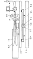
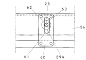
図14乃至図17は、第4実施例の封緘装置を示したものである。図14は既述の第1実施例における図3に相当する封緘側枠体の正面図、図15は同図4に相当するコンベア側枠体の正面図、図16は昇降移動操作部の構造を分解して示した説明用斜視図、図17は同様に昇降移動操作部の構造を説明するコンベア側枠体の要部の拡大正面図である。 14 to 17 show the sealing device of the fourth embodiment. 14 is a front view of a sealed side frame corresponding to FIG. 3 in the first embodiment, FIG. 15 is a front view of a conveyor side frame corresponding to FIG. 4, and FIG. FIG. 17 is an enlarged front view of the main part of the conveyor side frame for explaining the structure of the lifting / lowering operation unit.
該第4実施例も、前記第2、第3実施例の封緘装置と同様に、コンベア側枠体Aを昇降移動機構Dを備えていない構造とし、封緘側枠体Bを、部品配置板20としての上部枠板と基板21としての下部枠板とに分離して、これらの上下枠20,21間に昇降移動機構Dを設けてある構造としたものである。この第4実施例に示した昇降移動機構Dは、図14及び図16に示したように、部品配置板20としての上部枠板の下面の左右に、下方を解放して切り込み溝51とした側面視下向きU字形の横杆受け具50を、その天井板52をねじ固定し、その前後壁に形成した貫通小孔53と該横杆受け具50の切り込み溝51内に配置した横杆25に形成した小孔とにロックピン54を貫通させて、該横杆受け具50と横杆25とを連結してある。
In the fourth embodiment, similarly to the sealing devices of the second and third embodiments, the conveyor side frame A is not provided with the up-and-down moving mechanism D, and the sealing side frame B is replaced with the
これら左右の横杆受け具50,50の中間位置に、中央部分に操作軸28の先端受け穴56を形成した治具55を基板21の背面近くに配置固定し、この治具55の前方部の横杆25にも操作軸28を挿通させる軸受け穴58を形成してある。該実施例の横杆25にあっては、この軸受け穴58の形成部分は、操作軸28を加圧扁平化させて平板部57としたものとしてある。
A
他方、該実施例に示した操作軸28は、コンベア側枠体Aにおける前側フレーム5bの前面に固定した軸受け板60を、上下方向に沿った長穴61を備えたものとし、該長穴61の一側壁、図15〜17において、左側壁を鋸刃状の三角凹凸壁62に形成してあるものとし、その対向壁、同図における右側壁をゴム弾性を備えたクッション壁63に形成したものとしてある。また、操作ハンドル29Aに連結した操作軸28には、全周面でもよいが、図示のものにあっては、三角凹凸壁62に面した部分に、同三角凹凸壁62の凹凸と係合する凹凸面64を形成してある。
On the other hand, the
このようにしてあるので、該第4実施例に示した操作ハンドル29Aは、単に上下方向に操作して、その操作軸28を長穴61に沿って上下動させる。このとき、操作軸28はクッション壁63による弾性に抗しながらその凹凸面64が対向する三角凹凸壁62に接当しつつ上下移動する。操作ハンドル29Aの上下操作が終わるとこれらの三角凹凸壁62と凹凸面64とが係合してその位置を維持する。
Thus, the
この操作ハンドル29Aの上下方向操作に伴って、操作軸28は、その先端部が、前記治具55の操作軸先端受け穴56を支点として上下移動し、横杆25を挿通させた軸受け穴58を介して横杆25を上下方向に移動させる。この横杆25の上下移動によって部品配置板20の下面に固定した前記横杆受け具50を介して、部品配置板20の高さを昇降調節するようにしたものである。
As the operation handle 29A is operated in the up-and-down direction, the
以上の各実施例では、コンベア5の構造として、コンベア側枠体Aの長手方向、即ち、図において左右方向のほぼ全長に亘って配置してある構造として示したが、このコンベア5は、全長に亘って形成されているものである必要はなく、例えば、図において、右半部だけに無端ベルトとしてのコンベア5が形成され、左半部は、コンベアフレームの上面を形成する容器載置台としての容器載置面が形成されているものとして実施してもよい。
In each of the above embodiments, the structure of the
以上本発明の代表的な実施例について説明したが、本発明は必ずしも上記の実施例構造のみに特定されるものではない。例えば、封緘後の容器の後方に連結した粘着テープを切断するカッター機構や、コンベア昇降機構にあっては、その目的を達成できるものであればよいので別の機構に変更することができる。その他本発明はその目的を達成し、請求の範囲を逸脱しない範囲内で適宜修正したり変更して実施することができるものである。 Although typical embodiments of the present invention have been described above, the present invention is not necessarily limited to the above-described embodiments. For example, in the cutter mechanism for cutting the adhesive tape connected to the rear of the sealed container or the conveyor lifting mechanism, any mechanism can be used as long as it can achieve its purpose. Others The present invention achieves its object and can be implemented with appropriate modifications and changes without departing from the scope of the claims.
本発明は、スーパーマーケット等の商品加工室内や、店頭に載置して、加工惣菜その他の食品を収納した合成樹脂シート材製の容器を封緘してそのまま商品売り場に出して展示したり、商品の購買客の目の前で容器を封緘したり、場合によっては、商品の購買者自身が操作して容器の封緘をすることができるので、市場において大いに利用されると期待されるものである。 The present invention is placed in a merchandise processing room such as a supermarket or in a store, and a container made of a synthetic resin sheet material containing processed sugar beet and other foods is sealed and displayed as it is on the merchandise counter. Since the container can be sealed in front of the customer's eyes, or in some cases, the product purchaser himself can operate and seal the container, it is expected to be used greatly in the market.
A コンベア側枠体
B 封緘側枠体
C 包装用容器
D 昇降移動機構
G ギヤーボックス
M モータ
1 容器本体
2 蓋体
3 ヒンジ部
4 重合周縁部
5 コンベア
5a コンベアフレーム
5b コンベアフレーム
6 粘着テープ
7 封緘機構
8 カッター機構
81 切断刃体
10 圧着ローラ
14 ガイド部材
A Conveyor side frame B Sealing side frame C Packaging container D Lifting / moving mechanism G Gear
Claims (3)
物品を収容させて閉蓋姿勢とした容器を移動させるコンベア(5)を備えたコンベア側枠体(A)と、閉蓋姿勢とした前記容器(C)の重合周縁部(4)を粘着テープ(6)で封緘する封緘機構(7)を備えた封緘側枠体(B)と、
前記コンベア(5)を所定の方向に駆動させるモータ(M)と、
該モータ(M)の回転をコンベア(5)に伝達する回転伝達体とを備え、
前記コンベア側枠体(A)と封緘側枠体(B)とが互いに独立体として形成され、
これら両枠体(A,B)の少なくとも一方が昇降移動機構(D)を備え、この昇降移動機構(D)がコンベア側枠体(A)に装着されている場合はコンベア(5)の容器移送面を昇降させ、封緘側枠体(B)に装着されている場合は封緘機構(7)の後記一対の圧着ローラ間を昇降させる構成とされ、
前記封緘機構(7)は、前記粘着テープ(6)を断面V字形に屈曲させながら圧着ローラに向けて送り込むガイド部材(14)と、該ガイド部材(14)から送り込まれた粘着テープ(6)を容器の重合周縁部(4)に二つ折り状として接着させる上下一対の圧着ローラ(10,10)とを備え、
これら両枠体(A,B)の何れか一方に、封緘済み容器の移動方向後端側に連なる粘着テープの切断刃体(81)を備えたカッター機構(8)が配置され、
該カッター機構(8)の切断刃体(81)が、常時はテープ非切断箇所に待避していて、容器の存否を検知する光電管やリミットスイッチ等の関知機構の関知作用によってテープ切断位置への移動し、この移動に伴ってテープを切断する構造とされ、かつ、
前記圧着ローラ(10,10)のテープ送り速度とコンベア(5)の容器送り速度とが同期するように連動連結されている
包装用容器の卓上載置型封緘装置。 A desktop mounting type sealing device that seals the peripheral edge of the synthetic resin sheet material packaging container (C) composed of a container body and a cover body with an adhesive tape in a closed position,
Adhesive tape for the conveyor side frame (A) provided with a conveyor (5) for moving the containers in a closed position containing articles, and the overlapping peripheral edge (4) of the containers (C) in the closed position A sealing side frame (B) provided with a sealing mechanism (7) for sealing in (6);
A motor (M) for driving the conveyor (5) in a predetermined direction;
A rotation transmission body for transmitting the rotation of the motor (M) to the conveyor (5),
The conveyor side frame (A) and the sealing side frame (B) are formed as independent bodies,
When at least one of these frames (A, B) is provided with a lifting / lowering movement mechanism (D), and this lifting / lowering movement mechanism (D) is mounted on the conveyor-side frame (A), the container of the conveyor (5) When the transfer surface is raised and lowered, and is attached to the sealing side frame (B), the sealing mechanism (7) is configured to move up and down between a pair of pressure rollers,
The sealing mechanism (7) includes a guide member (14) for feeding the adhesive tape (6) toward the pressure roller while bending the adhesive tape (6) in a V-shaped cross section, and an adhesive tape (6) fed from the guide member (14). And a pair of upper and lower pressure-bonding rollers (10, 10) for adhering in a folded shape to the polymerization peripheral edge (4) of the container,
A cutter mechanism (8) provided with a cutting blade body (81) of an adhesive tape connected to the rear end side in the moving direction of the sealed container is disposed on either one of these two frame bodies (A, B),
The cutting blade (81) of the cutter mechanism (8) is always retracted to a non-cutting portion of the tape, and the detecting mechanism detects the presence or absence of the container. It is structured to move and cut the tape along with this movement, and
A table-top placement type sealing device for packaging containers that is interlocked and connected so that the tape feeding speed of the pressure roller (10, 10) and the container feeding speed of the conveyor (5) are synchronized.
Priority Applications (1)
| Application Number | Priority Date | Filing Date | Title |
|---|---|---|---|
| JP2009068495A JP2010222012A (en) | 2009-03-19 | 2009-03-19 | Table top mounting type sealing device for packaging container |
Applications Claiming Priority (1)
| Application Number | Priority Date | Filing Date | Title |
|---|---|---|---|
| JP2009068495A JP2010222012A (en) | 2009-03-19 | 2009-03-19 | Table top mounting type sealing device for packaging container |
Publications (1)
| Publication Number | Publication Date |
|---|---|
| JP2010222012A true JP2010222012A (en) | 2010-10-07 |
Family
ID=43039640
Family Applications (1)
| Application Number | Title | Priority Date | Filing Date |
|---|---|---|---|
| JP2009068495A Pending JP2010222012A (en) | 2009-03-19 | 2009-03-19 | Table top mounting type sealing device for packaging container |
Country Status (1)
| Country | Link |
|---|---|
| JP (1) | JP2010222012A (en) |
Cited By (6)
| Publication number | Priority date | Publication date | Assignee | Title |
|---|---|---|---|---|
| CN103693244A (en) * | 2013-12-23 | 2014-04-02 | 成都华正计量设备制造有限公司 | Clamping and bonding integrated machine |
| CN104111185A (en) * | 2014-06-19 | 2014-10-22 | 国家电网公司 | Edge covering system suitable for metal sample wafer corrosion resistance tests |
| CN105857758A (en) * | 2016-04-26 | 2016-08-17 | 杭州电子科技大学 | Adhesive tape packaging and bundling machine |
| CN108557180A (en) * | 2018-06-06 | 2018-09-21 | 山西乐教创科电子科技有限公司 | A kind of full-automatic plastic sealing machine |
| CN109214804A (en) * | 2018-08-29 | 2019-01-15 | 刘媛媛 | Supermarket unmanned self-service check of one kind uses article conveyer |
| CN120589284A (en) * | 2025-08-06 | 2025-09-05 | 湖南省长城铭泰新材料科技有限公司 | Plastic bag packaging device and method |
Citations (3)
| Publication number | Priority date | Publication date | Assignee | Title |
|---|---|---|---|---|
| JPS524367A (en) * | 1975-06-27 | 1977-01-13 | Matsushita Electric Works Ltd | Dressing mirror |
| JPH08217003A (en) * | 1995-02-20 | 1996-08-27 | Mamoru Kamo | Egg-container-sealing device |
| JP2009057062A (en) * | 2007-08-30 | 2009-03-19 | Naberu:Kk | Sealing device for synthetic resin-made packaging container |
-
2009
- 2009-03-19 JP JP2009068495A patent/JP2010222012A/en active Pending
Patent Citations (3)
| Publication number | Priority date | Publication date | Assignee | Title |
|---|---|---|---|---|
| JPS524367A (en) * | 1975-06-27 | 1977-01-13 | Matsushita Electric Works Ltd | Dressing mirror |
| JPH08217003A (en) * | 1995-02-20 | 1996-08-27 | Mamoru Kamo | Egg-container-sealing device |
| JP2009057062A (en) * | 2007-08-30 | 2009-03-19 | Naberu:Kk | Sealing device for synthetic resin-made packaging container |
Cited By (7)
| Publication number | Priority date | Publication date | Assignee | Title |
|---|---|---|---|---|
| CN103693244A (en) * | 2013-12-23 | 2014-04-02 | 成都华正计量设备制造有限公司 | Clamping and bonding integrated machine |
| CN104111185A (en) * | 2014-06-19 | 2014-10-22 | 国家电网公司 | Edge covering system suitable for metal sample wafer corrosion resistance tests |
| CN104111185B (en) * | 2014-06-19 | 2016-08-17 | 国家电网公司 | A kind of edge-coating system being applicable to coupon corrosion resistance test |
| CN105857758A (en) * | 2016-04-26 | 2016-08-17 | 杭州电子科技大学 | Adhesive tape packaging and bundling machine |
| CN108557180A (en) * | 2018-06-06 | 2018-09-21 | 山西乐教创科电子科技有限公司 | A kind of full-automatic plastic sealing machine |
| CN109214804A (en) * | 2018-08-29 | 2019-01-15 | 刘媛媛 | Supermarket unmanned self-service check of one kind uses article conveyer |
| CN120589284A (en) * | 2025-08-06 | 2025-09-05 | 湖南省长城铭泰新材料科技有限公司 | Plastic bag packaging device and method |
Similar Documents
| Publication | Publication Date | Title |
|---|---|---|
| WO2020107700A1 (en) | Automatic vending apparatus | |
| JP6976024B1 (en) | Packaging equipment | |
| CN210653738U (en) | Quantitative film type packaging machine convenient for changing packaging quality | |
| JP4838290B2 (en) | Desktop-type sealing device for packaging containers | |
| AU2017289325A1 (en) | A labelling apparatus | |
| CN111149840A (en) | Food material processing equipment | |
| EP2086843B1 (en) | Apparatus for packaging a product | |
| US5752363A (en) | Method and apparatus for manufacturing liquid dispensers | |
| JP4838291B2 (en) | Sealing device for packaging containers | |
| JP2006519738A (en) | Method for attaching an inner bag to a precise location on the inner surface of a container blank and a container with an inner bag | |
| JP2008007116A (en) | Packaging apparatus for packed article | |
| US4746321A (en) | Automatic machine for forming boxes of the double-plinth type | |
| EP2069204B1 (en) | Apparatus for packaging a pasty food product | |
| CN210113183U (en) | Side-sticking case sealer | |
| JP2005255194A (en) | Automatic filling device for packaged items in packaging bags | |
| KR101199060B1 (en) | Vinyl film heat press | |
| KR20110136158A (en) | Individual goods feeder for packaging | |
| JP7240727B2 (en) | Sprinkled food serving device | |
| US20200384754A1 (en) | Food dispensing module for a delaminating food dispensing system | |
| KR200178707Y1 (en) | Device for packing processed foodstuffs | |
| CN217100741U (en) | An automatic sealing machine for food packaging processing | |
| CN220536145U (en) | Plastic tableware packing plant | |
| JP2012224358A (en) | Pack seal machine for package | |
| KR20010007404A (en) | Film lapping equipment | |
| CN208630992U (en) | Cutting device for cutting sheets of packaging material |
Legal Events
| Date | Code | Title | Description |
|---|---|---|---|
| A711 | Notification of change in applicant |
Free format text: JAPANESE INTERMEDIATE CODE: A711 Effective date: 20101201 |
|
| A977 | Report on retrieval |
Free format text: JAPANESE INTERMEDIATE CODE: A971007 Effective date: 20110427 |
|
| A131 | Notification of reasons for refusal |
Free format text: JAPANESE INTERMEDIATE CODE: A131 Effective date: 20110621 |
|
| A02 | Decision of refusal |
Free format text: JAPANESE INTERMEDIATE CODE: A02 Effective date: 20111018 |