JP2010222995A - Internal combustion engine accumulator system - Google Patents
Internal combustion engine accumulator system Download PDFInfo
- Publication number
- JP2010222995A JP2010222995A JP2009068347A JP2009068347A JP2010222995A JP 2010222995 A JP2010222995 A JP 2010222995A JP 2009068347 A JP2009068347 A JP 2009068347A JP 2009068347 A JP2009068347 A JP 2009068347A JP 2010222995 A JP2010222995 A JP 2010222995A
- Authority
- JP
- Japan
- Prior art keywords
- pressure
- control valve
- tank
- exhaust
- valve
- Prior art date
- Legal status (The legal status is an assumption and is not a legal conclusion. Google has not performed a legal analysis and makes no representation as to the accuracy of the status listed.)
- Pending
Links
Images


Classifications
-
- Y—GENERAL TAGGING OF NEW TECHNOLOGICAL DEVELOPMENTS; GENERAL TAGGING OF CROSS-SECTIONAL TECHNOLOGIES SPANNING OVER SEVERAL SECTIONS OF THE IPC; TECHNICAL SUBJECTS COVERED BY FORMER USPC CROSS-REFERENCE ART COLLECTIONS [XRACs] AND DIGESTS
- Y02—TECHNOLOGIES OR APPLICATIONS FOR MITIGATION OR ADAPTATION AGAINST CLIMATE CHANGE
- Y02T—CLIMATE CHANGE MITIGATION TECHNOLOGIES RELATED TO TRANSPORTATION
- Y02T10/00—Road transport of goods or passengers
- Y02T10/10—Internal combustion engine [ICE] based vehicles
- Y02T10/12—Improving ICE efficiencies
Landscapes
- Supercharger (AREA)
Abstract
Description
本発明は、排気圧を蓄圧し、該排気圧を所定の供給先へと供給可能な蓄圧タンクを備える内燃機関蓄圧システムの技術分野に関する。 The present invention relates to a technical field of an internal combustion engine pressure accumulation system including a pressure accumulation tank that accumulates exhaust pressure and can supply the exhaust pressure to a predetermined supply destination.
エンジンの出力向上を目的として、エンジンにターボチャージャ(過給器)を搭載する技術が知られている。更に、このようなターボチャージャにエアアシストを行うために、排気管内の排気圧を蓄圧させて、背圧エネルギを回収及び利用する技術が知られている。 For the purpose of improving engine output, a technique for installing a turbocharger (supercharger) in the engine is known. Furthermore, in order to perform air assist for such a turbocharger, a technique for collecting and using back pressure energy by accumulating exhaust pressure in the exhaust pipe is known.
特許文献1には、車両の減速時に、排気管に設けられる排気遮断弁を閉弁して、蓄圧タンクに圧力エネルギを蓄え、より大きなトルクが必要とされる場合にエアアシストを行う蓄圧タンクシステムが開示されている。
また、特許文献2には、車両の減速時に蓄圧タンクに圧力エネルギを蓄えるエネルギ回収装置において、車両の減速度が大きくなりすぎないように吸排気弁の開度を制御する構成が開示されている。
また、特許文献3及び4には、エアアシスト時に車両のアクセル開度やギア位置に基づいて、流量制御弁の開弁タイミングや開弁速度を変更する構成が開示されている。
排気管に設けられる排気遮断弁を閉弁し、高まった排気圧を蓄圧タンクに回収する構成において、一般的に、排気管と蓄圧タンクとは流量制御弁を介して連通されている。そして、この流量制御弁の開閉弁に伴って、蓄圧タンクに蓄圧された排気によるエアアシストが実施される。 In the configuration in which the exhaust cutoff valve provided in the exhaust pipe is closed and the increased exhaust pressure is recovered in the pressure accumulation tank, the exhaust pipe and the pressure accumulation tank are generally communicated with each other via a flow control valve. And the air assist by the exhaust_gas | exhaustion accumulated in the pressure accumulation tank is implemented with the on-off valve of this flow control valve.
しかしながら、このような蓄圧タンクを備える過給システムにおいては、蓄圧タンクからのエアアシスト時に、流量制御弁の開弁に伴って大きな駆動力が必要となり、該流量制御弁のアクチュエータに過負荷がかかる場合がある。特に、流量制御弁の前後における排気圧及び蓄圧タンク圧の圧力差が大きい場合に、このような過負荷は顕著となる。 However, in a supercharging system including such a pressure accumulating tank, a large driving force is required as the flow control valve is opened during air assist from the pressure accumulating tank, and the actuator of the flow control valve is overloaded. There is a case. In particular, when the pressure difference between the exhaust pressure and the accumulator tank pressure before and after the flow control valve is large, such overload becomes significant.
尚、このような流量制御弁など比較的高精度での開閉制御が必要とされる弁装置には、一般的にステップモータ式の弁装置が用いられているが、このような過負荷の影響によって、弁装置への入力パルス信号とモータ回転との周期が失われる虞がある。この場合、モータの中心に位置するロータの脱調を引き起こし、また、弁装置の開度が不正確となりかねない技術的な問題に繋がる。 Note that step motor type valve devices are generally used for such valve devices that require relatively high-precision opening / closing control such as flow control valves. As a result, the cycle of the input pulse signal to the valve device and the motor rotation may be lost. In this case, the rotor located at the center of the motor is stepped out, and the opening degree of the valve device may be inaccurate, leading to technical problems.
また、上述した特許文献に記載されるように、エアアシスト時の流量制御弁の開弁タイミングを遅らせることでこのような流量制御弁への悪影響を抑制する技術も知られている。しかしながら、流量制御弁の開弁タイミングを遅らせることでエアアシストの開始も遅くなるため、エアアシスト効果が低減してしまうこともあり好ましくない。 In addition, as described in the above-described patent document, there is also known a technique for suppressing such an adverse effect on the flow control valve by delaying the opening timing of the flow control valve at the time of air assist. However, since the start of air assist is delayed by delaying the opening timing of the flow control valve, the air assist effect may be reduced, which is not preferable.
本発明は、上述した問題点に鑑みて為されたものであり、好適なエアアシストを可能とする内燃機関蓄圧システムを提供することを課題とする。 The present invention has been made in view of the above-described problems, and an object of the present invention is to provide an internal combustion engine pressure accumulating system that enables suitable air assist.
上記課題を解決するために、本発明の内燃機関蓄圧システムは、車両に搭載される内燃機関に連通する排気管に設けられる排気遮断弁を閉弁することで排気圧を蓄圧し、該排気圧を所定の供給先へと供給可能な蓄圧タンクを備える内燃機関蓄圧システムであって、前記排気管、前記蓄圧タンク及び前記所定の供給先を連通するとともに、前記排気管内のガスを前記蓄圧タンクへと供給し、前記蓄圧タンク内のガスを前記所定の供給先へと供給するガス通路と、前記ガス通路における前記蓄圧タンクと前記所定の供給先との間に設けられ、全開する全開位置と全閉する全閉位置との間で開度を調整可能な流量制御弁と、前記流量制御弁の開閉動作を制御する制御手段とを備え、前記制御手段は、前記排気管内の排気圧及び前記蓄圧タンク内のタンク圧に基づいて、前記流量制御弁の開弁速度を決定する。 In order to solve the above-described problems, an internal combustion engine pressure accumulation system according to the present invention accumulates exhaust pressure by closing an exhaust cutoff valve provided in an exhaust pipe communicating with an internal combustion engine mounted on a vehicle. An internal combustion engine pressure accumulating system comprising a pressure accumulating tank capable of supplying a gas to a predetermined supply destination, wherein the exhaust pipe, the pressure accumulating tank, and the predetermined supply destination communicate with each other, and gas in the exhaust pipe is supplied to the pressure accumulating tank. And a gas passage for supplying the gas in the accumulator tank to the predetermined supply destination, and a fully open position and a full opening position that are provided between the pressure accumulation tank and the predetermined supply destination in the gas passage. A flow rate control valve capable of adjusting an opening degree between the fully closed position and a control unit for controlling an opening / closing operation of the flow rate control valve, wherein the control unit includes an exhaust pressure and an accumulated pressure in the exhaust pipe. In tank Based on the click pressure, determines the opening speed of the flow control valve.
本発明の内燃機関蓄圧システムによれば、典型的には、内燃機関における各気筒に連通する排気マニホールドである排気管が、該排気管の下流側に設けられる排気遮断弁を閉弁することで密閉され、気筒より排出される排気が排気管内に蓄圧されるよう構成されている。また、該排気管と蓄圧タンクとを連通するようにガス通路が設けられており、該ガス通路を介して排気管内に蓄圧された排気が蓄圧タンクへと流入する。 According to the internal combustion engine pressure accumulating system of the present invention, typically, an exhaust pipe that is an exhaust manifold communicating with each cylinder in the internal combustion engine closes an exhaust cutoff valve provided on the downstream side of the exhaust pipe. The exhaust gas is sealed and the exhaust gas discharged from the cylinder is accumulated in the exhaust pipe. Further, a gas passage is provided so as to connect the exhaust pipe and the pressure accumulation tank, and the exhaust gas accumulated in the exhaust pipe flows into the pressure accumulation tank through the gas passage.
このように蓄圧タンクへの排気の流入によって、蓄圧タンク内に排気圧が蓄圧される。そして、タンク圧が目標圧力まで達した後、蓄圧工程が終了したものと判断される。このときの目標圧力とは、少なくともエアアシストを行うために十分なタンク圧であって、適宜何らかの手段によって決定されて良いものである。 Thus, the exhaust pressure is accumulated in the pressure accumulation tank by the inflow of the exhaust gas into the pressure accumulation tank. Then, after the tank pressure reaches the target pressure, it is determined that the pressure accumulation process has been completed. The target pressure at this time is a tank pressure that is at least sufficient to perform air assist, and may be appropriately determined by some means.
このように蓄圧タンクに蓄圧された排気圧は、例えば車両の加速時など、より多くのエンジントルクを要する場合などに、ガス通路を介して所定の供給先へと供給される。このような蓄圧された排気の供給をエアアシストと称する。このとき所定の供給先とは、例えば、排気管において排気遮断弁の上流側に設けられるターボ過給機のタービンなどであって、少なくとも過給効果によって幾らかなりとエンジントルクの向上を実現可能である各種装置を示す趣旨である。 The exhaust pressure accumulated in the pressure accumulation tank in this way is supplied to a predetermined supply destination via the gas passage when more engine torque is required, for example, when the vehicle is accelerated. Such supply of accumulated exhaust gas is referred to as air assist. At this time, the predetermined supply destination is, for example, a turbocharger turbine provided upstream of the exhaust cutoff valve in the exhaust pipe, and at least some improvement in engine torque can be realized due to the supercharging effect. The purpose is to show various devices.
ガス通路における蓄圧タンクと所定の供給先との間には、全閉位置と全開位置との間で開度の調整が可能な流量制御弁が設けられている。従って、流量制御弁の閉弁時には、蓄圧タンクと所定の供給先との間には、典型的にはガス交換は行われず、流量制御弁の開弁に伴って、蓄圧タンク内に蓄圧された排気が所定の供給先へと供給される。 A flow rate control valve capable of adjusting the opening degree between the fully closed position and the fully opened position is provided between the pressure accumulation tank and the predetermined supply destination in the gas passage. Therefore, when the flow rate control valve is closed, gas exchange is not typically performed between the pressure accumulation tank and a predetermined supply destination, and pressure is accumulated in the pressure accumulation tank as the flow rate control valve is opened. Exhaust gas is supplied to a predetermined supply destination.
尚、ガス通路は、排気管及び蓄圧タンクを接続する構成と、蓄圧タンク及び所定の供給先を接続する構成との間で互いに独立した構成であっても良い。また、所定の供給先が、排気管に設けられるターボ過給機のタービンであるよう構成される場合など、ガスの移動経路が重複する場合には、一つの管材をガス通路として排気管及び蓄圧タンクを連通するよう構成されていても良い。 Note that the gas passage may have a configuration that is independent between a configuration that connects the exhaust pipe and the pressure storage tank and a configuration that connects the pressure storage tank and a predetermined supply destination. In addition, when the gas supply path overlaps, such as when the predetermined supply destination is configured to be a turbocharger turbine provided in the exhaust pipe, the exhaust pipe and the pressure accumulator with one pipe material as the gas passage You may be comprised so that a tank may be connected.
また、蓄圧タンクへの蓄圧終了後に、排気管やガス通路内に残留する排気は、排気遮断弁やEGR弁、排気バイパス弁などの開弁に伴って、所定の排気先へと排気されることが好ましい。これによって、蓄圧終了後の排気管内の排気圧を低減させることが可能となり、その後アクセル開度の上昇に伴って内燃機関への燃料の供給が再開された後に、排気管内圧が高まることに起因するエンジントルクの低減などの技術的な問題を抑制出来る。 In addition, exhaust gas remaining in the exhaust pipe and gas passage after the completion of accumulating pressure in the accumulator tank is exhausted to a predetermined exhaust destination when the exhaust shutoff valve, EGR valve, exhaust bypass valve, etc. are opened. Is preferred. As a result, it is possible to reduce the exhaust pressure in the exhaust pipe after the end of pressure accumulation, and then the exhaust pipe internal pressure increases after the fuel supply to the internal combustion engine is resumed as the accelerator opening increases. Technical problems such as engine torque reduction can be suppressed.
本発明の内燃機関の蓄圧システムには、特に流量制御弁の開閉を制御する制御手段が設けられている。該制御手段は、典型的には当該蓄圧システムが搭載される車両に搭載されるECU(Engine Control Unit)であり、後述する種々のセンサから入力されるデータに基づき、流量制御弁の開度及び開閉速度を適宜決定して、開閉を制御する。 The pressure accumulation system for the internal combustion engine of the present invention is provided with a control means for controlling the opening / closing of the flow control valve. The control means is typically an ECU (Engine Control Unit) mounted on a vehicle on which the pressure accumulating system is mounted, and based on data input from various sensors to be described later, The opening / closing speed is appropriately determined to control opening / closing.
より具体的には、制御手段は、蓄圧タンクからの排気の供給(以下、適宜エアアシストと記載する)の際、排気管内の排気圧及び蓄圧タンク内のタンク圧の夫々に基づいて、流量制御弁の開度及び開閉速度を決定する。 More specifically, the control means controls the flow rate based on the exhaust pressure in the exhaust pipe and the tank pressure in the accumulator tank when supplying exhaust from the accumulator tank (hereinafter referred to as air assist as appropriate). Determine the valve opening and opening / closing speed.
流量制御弁の前後における圧力差、つまり、蓄圧タンク内のタンク圧と、排気管内の排気圧との圧力差が大きい場合、流量制御弁の開弁時には過負荷がかかり、比較的大きな駆動力が必要とされる。このため、圧力差が大きい場合に流量制御弁の開弁を実施しようとする場合、流量制御弁の開弁に用いられるアクチュエータ系に脱調が生じる可能性がある。 If the pressure difference before and after the flow control valve, that is, the pressure difference between the tank pressure in the accumulator tank and the exhaust pressure in the exhaust pipe is large, an overload is applied when the flow control valve is opened, and a relatively large driving force is generated. Needed. For this reason, when attempting to open the flow control valve when the pressure difference is large, the actuator system used for opening the flow control valve may step out.
そこで、本発明の蓄圧システムに備えられる制御手段は、流量制御弁の前後のタンク圧及び排気圧を検出、または推定し、後に詳述するようにそれらの圧力差に基づいて流量制御弁の開弁速度を決定した上で開弁動作を制御している。このため、圧力差に起因する流量制御弁の開弁時の負荷を好適に低減させ、アクチュエータの脱調などの可能性を抑制し得る開弁制御が可能となる。 Therefore, the control means provided in the pressure accumulation system of the present invention detects or estimates the tank pressure and the exhaust pressure before and after the flow control valve, and opens the flow control valve based on the pressure difference as described in detail later. The valve opening operation is controlled after the valve speed is determined. Therefore, it is possible to perform valve opening control that can suitably reduce the load when the flow rate control valve is opened due to the pressure difference and suppress the possibility of actuator step-out.
本発明の内燃機関蓄圧システムの一つの態様は、前記制御手段は、前記排気管内の排気圧及び前記蓄圧タンク内のタンク圧の差分に基づいて、前記流量制御弁の開弁速度を決定する。 In one aspect of the internal combustion engine pressure accumulation system of the present invention, the control means determines the valve opening speed of the flow rate control valve based on the difference between the exhaust pressure in the exhaust pipe and the tank pressure in the pressure accumulation tank.
この態様によれば、制御手段は、ガス通路における流量制御弁の前後の圧力差、つまり排気圧及びタンク圧の圧力差に基づいて、流量制御弁の開弁速度を決定した上で、開閉弁動作を実施する。 According to this aspect, the control means determines the opening speed of the flow control valve based on the pressure difference before and after the flow control valve in the gas passage, that is, the pressure difference between the exhaust pressure and the tank pressure. Perform the operation.
このように構成することで、タンク圧と排気圧との圧力差に起因するアクチュエータへの負荷に基づき、流量制御弁の開弁動作を制御することが可能となる。従って、アクチュエータへの過負荷に起因する種々の不具合を比較的容易かつ好適に抑制可能となる。 With this configuration, it is possible to control the valve opening operation of the flow control valve based on the load on the actuator caused by the pressure difference between the tank pressure and the exhaust pressure. Therefore, it is possible to suppress various problems caused by the overload on the actuator relatively easily and suitably.
本発明の内燃機関蓄圧システムの他の態様は、前記制御手段は、前記排気管内の排気圧及び前記蓄圧タンク内のタンク圧の差分が大きいほど、前記流量制御弁の開弁速度が小さくなるよう前記流量制御弁の開弁速度を決定する。 In another aspect of the internal combustion engine accumulator system of the present invention, the control means is configured such that the valve opening speed of the flow control valve decreases as the difference between the exhaust pressure in the exhaust pipe and the tank pressure in the accumulator tank increases. A valve opening speed of the flow control valve is determined.
この態様によれば、タンク圧と排気圧との圧力差が比較的大きい場合には、流量制御弁の開度を小さくし、タンク圧と排気圧との圧力差が小さくなるにつれて、流量制御弁の開度を大きくするように、流量制御弁の開弁速度が決定される。つまり、この態様での制御手段は、エアアシストの実施中にタンク圧と排気圧との圧力差を看視し、該圧力差の変化に応じて流量制御弁の開弁速度を適宜決定するよう構成される。 According to this aspect, when the pressure difference between the tank pressure and the exhaust pressure is relatively large, the opening degree of the flow rate control valve is decreased, and the flow rate control valve is decreased as the pressure difference between the tank pressure and the exhaust pressure is decreased. The valve opening speed of the flow rate control valve is determined so as to increase the opening degree. That is, the control means in this mode observes the pressure difference between the tank pressure and the exhaust pressure during the air assist, and appropriately determines the opening speed of the flow control valve according to the change in the pressure difference. Composed.
典型的に、エアアシストの開始時にはタンク圧と排気圧との圧力差が最も大きいため、比較的低い開弁速度で流量制御弁の開弁が開始される。従って、タンク圧と排気圧との圧力差が最も大きいエアアシストの開始時には、流量制御弁の開度が小さくなる(言い換えれば、開度が小さい状態が相対的に長い時間維持される)。そして、蓄圧タンク内の排気が放出されていくことで圧力差が小さくなるにつれて、流量制御弁の開弁速度は上昇するよう制御される。従って、流量制御弁の開度が徐々に且つ一層大きくなっていく。 Typically, since the pressure difference between the tank pressure and the exhaust pressure is the largest at the start of air assist, the flow control valve is opened at a relatively low valve opening speed. Accordingly, at the start of air assist with the largest pressure difference between the tank pressure and the exhaust pressure, the opening degree of the flow control valve becomes small (in other words, the state where the opening degree is small is maintained for a relatively long time). Then, the opening speed of the flow rate control valve is controlled to increase as the pressure difference decreases as the exhaust gas in the pressure accumulation tank is released. Accordingly, the opening degree of the flow control valve gradually and further increases.
このように構成すれば、流量制御弁の前後の圧力差が比較的大きい時点では流量制御弁が比較的低い開弁速度で徐々に開弁するよう制御されるため、流量制御弁のアクチュエータに係る負荷を好適に低減させることが可能となる。その後も、流量制御弁の前後の圧力差に応じて流量制御弁の開弁速度が適宜決定されるため、動作不良の発生を好適に抑制しつつ、応答性の良好な流量制御弁の開弁動作を実施することが可能となる。 With this configuration, the flow control valve is controlled to gradually open at a relatively low valve opening speed when the pressure difference before and after the flow control valve is relatively large. The load can be suitably reduced. After that, since the opening speed of the flow control valve is appropriately determined according to the pressure difference before and after the flow control valve, it is possible to open the flow control valve with good responsiveness while suitably suppressing the occurrence of malfunction. The operation can be performed.
本発明の内燃機関蓄圧システムの他の態様は、前記制御手段は、前記排気管内の排気圧及び前記蓄圧タンク内のタンク圧の差分が所定の閾値以下の場合、前記流量制御弁の開弁動作を停止する。 In another aspect of the internal combustion engine accumulator system of the present invention, the control means opens the flow control valve when the difference between the exhaust pressure in the exhaust pipe and the tank pressure in the accumulator tank is not more than a predetermined threshold value. To stop.
この態様によれば、エアアシストの実施に伴って、蓄圧タンク内のタンク圧が低下し、他方で排気管内の排気圧が上昇した後、排気圧とタンク圧との圧力差が所定の閾値以下となった場合、流量制御弁の動作が停止される(言い換えれば、開弁速度=0となる)。このため、流量制御弁の開度は、所定の開度に維持される。 According to this aspect, as the air assist is performed, the tank pressure in the accumulator tank decreases and, on the other hand, the exhaust pressure in the exhaust pipe increases, and then the pressure difference between the exhaust pressure and the tank pressure is equal to or less than a predetermined threshold value. In this case, the operation of the flow control valve is stopped (in other words, the valve opening speed = 0). For this reason, the opening degree of the flow control valve is maintained at a predetermined opening degree.
このとき、流量制御弁の所定の開度とは、典型的には流量制御弁の最大開度であることが好ましい。このように所定の開度を流量制御弁の最大開度に設定した場合、この態様での制御手段は、好適には排気圧とタンク圧との圧力差が所定の閾値まで低下するタイミングにおいて、流量制御弁の開度が所定の最大開度となるよう流量制御弁の開弁速度を決定する。 At this time, the predetermined opening degree of the flow control valve is typically preferably the maximum opening degree of the flow control valve. Thus, when the predetermined opening is set to the maximum opening of the flow control valve, the control means in this aspect is preferably a timing at which the pressure difference between the exhaust pressure and the tank pressure decreases to a predetermined threshold. The opening speed of the flow control valve is determined so that the opening of the flow control valve becomes a predetermined maximum opening.
尚、このような流量制御弁の所定の最大開度とは、制御手段による流量制御弁の一連の開閉弁動作における最大の開度を示す趣旨であって、好適なエアアシストを実施可能とするために十分な開度であれば、適宜決定されていて構わない。また、このような最大開度とは、必ずしも流量制御弁の全開位置に相当する開度を示す趣旨ではない。 The predetermined maximum opening degree of the flow rate control valve is intended to indicate the maximum opening degree in the series of on-off valve operations of the flow rate control valve by the control means, and allows suitable air assist to be implemented. Therefore, as long as the opening is sufficient, it may be determined appropriately. Further, such a maximum opening does not necessarily indicate an opening corresponding to the fully open position of the flow control valve.
このように構成すれば、排気圧とタンク圧との圧力差に応じて、流量制御弁の開度を、好適なエアアシストの実施が可能な位置に維持する。このため、好適なエアアシストの実施が可能となるとともに、流量制御弁を必要以上に開弁させることなく、従って、閉弁時の流量制御弁の閉弁量を抑制することが可能となる。 If comprised in this way, according to the pressure difference of exhaust pressure and a tank pressure, the opening degree of a flow control valve will be maintained in the position which can implement suitable air assist. For this reason, it is possible to perform a suitable air assist, and it is possible to suppress the valve closing amount of the flow control valve when the valve is closed without opening the flow control valve more than necessary.
本発明の内燃機関蓄圧システムの他の態様は、前記制御手段は、前記流量制御弁の開度が所定の開度に達した後、前記流量制御弁の閉弁を開始する。 In another aspect of the internal combustion engine pressure accumulating system of the present invention, the control means starts closing the flow control valve after the opening of the flow control valve reaches a predetermined opening.
この態様によれば、エアアシスト中に流量制御弁の開度が所定の開度まで達した後、流量制御弁の閉弁が開始される(言い換えれば、開弁速度<0となる)。このとき、制御手段は、流量制御弁が所定の開度まで達した後即座に閉弁を開始することが好ましく、また、開弁速度の絶対値が比較的小さい状態を維持するように徐々に閉弁を行うことが好ましい。尚、このときの所定の開度とは、典型的には、上述した流量制御弁の最大開度である。 According to this aspect, after the opening degree of the flow control valve reaches a predetermined opening degree during the air assist, the closing of the flow control valve is started (in other words, the valve opening speed <0). At this time, the control means preferably starts to close immediately after the flow control valve reaches a predetermined opening, and gradually increases so that the absolute value of the valve opening speed is kept relatively small. It is preferable to close the valve. Note that the predetermined opening at this time is typically the maximum opening of the flow control valve described above.
一般的に、流量制御弁を急激に閉弁する場合にも、流量制御弁の前後の排気圧とタンク圧との圧力差によって、アクチュエータに負荷がかかり、脱調が生じる虞がある。尚、このような急激な閉弁とは、具体的には、比較的大きな開度から短期間(つまり、比較的高い閉速度)で全閉位置まで流量制御弁を駆動させるような閉弁を示し趣旨である。 In general, even when the flow control valve is suddenly closed, a load is applied to the actuator due to the pressure difference between the exhaust pressure before and after the flow control valve and the tank pressure, and step-out may occur. Specifically, such a sudden valve closing is a valve closing that drives the flow control valve from a relatively large opening to a fully closed position in a short period (that is, a relatively high closing speed). It is an intention.
他方、このような制御手段の動作によれば、エアアシスト中に流量制御弁を徐々に閉弁することで、流量制御弁の開度を低減させることが出来る。このため、例えば排気圧とタンク圧とが等しくなったタイミングなど、エアアシストの実施を終了する場合において、流量制御弁の開度が比較的小さいため、上述したような急激な閉弁と同程度に高い閉弁速度で流量制御弁を全閉位置まで駆動させたとしても、アクチュエータにかかる負荷は低減される。 On the other hand, according to the operation of such a control means, the opening degree of the flow control valve can be reduced by gradually closing the flow control valve during air assist. For this reason, when the air assist is finished, for example, when the exhaust pressure and the tank pressure become equal, the opening degree of the flow control valve is relatively small, and therefore, similar to the sudden closing as described above. Even if the flow control valve is driven to the fully closed position at a very high valve closing speed, the load on the actuator is reduced.
従って、流量制御弁の閉弁時にアクチュエータの脱調を好適に抑制することが可能となる。 Therefore, the step-out of the actuator can be suitably suppressed when the flow control valve is closed.
本発明の内燃機関蓄圧システムの他の態様は、前記制御手段は、前記排気管内の排気圧及び前記蓄圧タンク内のタンク圧に基づく前記流量制御弁の開弁速度のマップを参照することで、前記流量制御弁の開弁速度を決定する。 In another aspect of the internal combustion engine pressure accumulation system of the present invention, the control means refers to a map of the valve opening speed of the flow rate control valve based on the exhaust pressure in the exhaust pipe and the tank pressure in the pressure accumulation tank, A valve opening speed of the flow control valve is determined.
この態様によれば、制御手段は、流量制御弁の動作制御に係る各種パラメータ(例えば、タンク圧、排気圧、流量制御弁の開度及び開弁速度)の夫々が関連付けられて決定されるマップを備えている。好適には、該マップが格納されて成る典型的にはメモリなどのデータの記録及び参照が可能な記録手段を備えて構成される。そして、該記録手段に格納されるマップを参照することで制御手段は、流量制御弁の動作制御を実施する。 According to this aspect, the control means is a map in which various parameters relating to the operation control of the flow control valve (for example, the tank pressure, the exhaust pressure, the opening degree of the flow control valve, and the valve opening speed) are determined in association with each other. It has. Preferably, the map is stored, and typically comprises a recording means capable of recording and referring to data such as a memory. The control means controls the operation of the flow control valve by referring to the map stored in the recording means.
このように構成することで、上述の各態様に記載される制御手段による流量制御弁の動作制御を比較的容易に実施することが可能となる。 By comprising in this way, it becomes possible to implement comparatively easily control of operation | movement of the flow control valve by the control means described in each above-mentioned aspect.
本発明の内燃機関蓄圧システムの他の態様は、前記排気管内の排気圧及び前記蓄圧タンク内のタンク圧の夫々を推定する推定手段を更に備える。 Another aspect of the internal combustion engine pressure accumulation system of the present invention further includes estimation means for estimating the exhaust pressure in the exhaust pipe and the tank pressure in the pressure accumulation tank.
この態様によれば、制御手段は、蓄圧タンクに設けられるタンク圧センサ及びガス通路内の排気圧を計測可能な排気圧センサなどの種々のセンサ類に接続され、各種計測データの入力を随時受けるよう構成される。 According to this aspect, the control means is connected to various sensors such as a tank pressure sensor provided in the pressure accumulation tank and an exhaust pressure sensor capable of measuring the exhaust pressure in the gas passage, and receives various measurement data as needed. It is configured as follows.
このため、上述した各態様に係る動作を比較的容易に実施可能となる。 For this reason, the operation | movement which concerns on each aspect mentioned above can be implemented comparatively easily.
本発明のこのような作用及び他の利得は次に説明する実施形態から明らかにされる。 Such an operation and other advantages of the present invention will become apparent from the embodiments described below.
以下、図面を参照して、本発明の好適な各種実施形態について説明する。 Various preferred embodiments of the present invention will be described below with reference to the drawings.
(1)基本構成
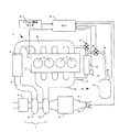
図1は、本発明の実施形態に係る内燃機関蓄圧システムが組み込まれた内燃機関(以下、エンジンと称する)1を概略的に示す模式図である。
(1) Basic Configuration FIG. 1 is a schematic diagram schematically showing an internal combustion engine (hereinafter referred to as an engine) 1 in which an internal combustion engine pressure accumulating system according to an embodiment of the present invention is incorporated.
図1に示されるように、本実施形態に係る蓄圧システム20は、例えば、エンジン1に設けられ、排気遮断弁10、EGR通路11、EGR弁13、排気圧センサ14、蓄圧タンク21、ガス通路22、流量制御弁23、タンク圧センサ24、ECU30及びアクセル開度センサ32等を含んで構成される。
As shown in FIG. 1, the
エンジン1は、車両に走行用動力源として搭載されるディーゼルエンジンであり、複数(図1の例では4つ)のシリンダ2を有する機関本体3と、各シリンダ2にそれぞれ接続される吸気通路4及び排気通路5とを備えている。吸気通路4には、吸気を濾過するエアクリーナ6と、ターボ過給機7のコンプレッサ7aと、吸気を冷却するためのインタークーラ8とが設けられている。排気通路5には、ターボ過給機7のタービン7bと、排気を浄化するための触媒コンバータ9と、排気通路5を全閉する全閉位置と排気通路5を全開する全開位置とに切り替え可能な排気遮断弁10とが設けられている。
The
排気通路5と吸気通路4とは、本発明における「ガス通路」の一部を形成するEGR通路11にて連通されている。図1に示したようにEGR通路11は、排気通路5の一部を形成する排気マニホールド5aと吸気通路4の一部を形成する吸気マニホールド4aとを接続している。EGR通路11には、排気通路5から吸気通路4に導かれる排気(以下、EGRガスと称することがある)を冷却するためのEGRクーラ12、EGRガスの流量を調整するためのEGR弁13と、EGRガスの圧力(言い換えれば排気圧)に対応する信号を出力するための排気圧センサ14とが設けられている。また、本実施形態におけるEGR弁13は、ステッピングモータ式の弁装置であり、ECU30からの制御パルス信号に応じて開度並びに開弁及び閉弁時の速度を比較的高精度で制御可能に構成されている。その他、特に記載されること以外は、EGR通路11、EGRクーラ12及びEGR弁13などは、公知のEGRシステムの一部として動作するよう構成されていても良い。
The
各シリンダ2には、シリンダ2内に燃料を噴射するための不図示のインジェクタ夫々設けられ、各インジェクタは、インジェクタに供給される高圧の燃料が蓄えられる不図示のコモンレールに接続されている。
Each
蓄圧タンク21は、加圧されたガスを溜めることが可能な圧力容器として構成されている。蓄圧タンク21には、ガスとして空気及び排気の少なくともいずれか一方が貯留される。蓄圧タンク21の内部には、例えば、不図示の吸着材が収容されている。該吸着材は、ガスを吸着可能かつ吸着したガスを放出可能な物質であれば良く、例えば活性炭が用いられる。この他、吸着材としては、例えばゼオライト、アルミナ、カーボンモレキュラーシーブなどが用いられる。尚、吸着材は、単一の物質に限定されず、これらの物質が混合されたものでも良い。蓄圧タンク21内には、ガスとともに吸着材が外部に排出されることを防止する不図示の仕切り板が設けられていても良い。
The
蓄圧タンク21は、ガス通路22にてEGR通路11と接続されている。ガス通路22は、本発明における「ガス通路」の一部を構成する部位であり、また、中には流量制御弁23が設けられている。流量制御弁23は、蓄圧タンク21の内部とEGR通路11とが接続されるようにガス通路22を全開する接続位置(以下、全開位置と称する)と蓄圧タンク21の内部とEGR通路11との接続が遮断されるようにガス通路22を全閉する遮断位置(以下、全閉位置と称する)との間で開度を段階的または連続的に調整可能であり、このため、ガス通路22を流れるガスの流量を制御することが出来る。蓄圧タンク21には、蓄圧タンク21内部の圧力(以下、タンク圧と称する)に対応する信号を出力するタンク圧センサ24とが設けられている。
The
本実施形態における流量制御弁23の動作は、エンジンコントロールユニット(ECU)30にて制御される。ECU30は、マイクロプロセッサ及びその動作に必要なRAM、ROM等の周辺機器を含んだコンピュータとして構成され、エンジン1に設けられた各種センサからの出力信号に基づいて排気遮断弁10、EGR弁13、及びインジェクタなどの動作をそれぞれ制御し、これによりエンジン1の運転状態を制御する周知のコンピュータユニットである。ECU30は、例えばエンジン1の回転数が予め決定した所定の燃料カット回転数以上であり、かつアクセル開度が0%すなわちアクセルペダルが踏まれていない場合、各シリンダ2への燃料供給が停止されるように各インジェクタの動作を制御する。以下、この制御を燃料カット制御と称することがある。
The operation of the
また、ECU30は、エンジン1の運転状態に応じて適正な量のEGRガスが吸気通路4に導入されるようにEGR弁13の開度を調整する。この他、ECU30はエンジン1の運転状態に応じて排気遮断弁10の開度を調整する。このような制御を行う際に参照するセンサとしてECU30には、例えばエンジン1のクランク軸の回転速度(回転数)に対応する信号を出力するクランク角センサ31及びアクセル開度に対応する信号を出力するアクセル開度センサ32などが接続される。また、ECU30には、排気圧センサ14及びタンク圧センサ24も接続される。尚、これらの他にもECU30には種々の不図示のセンサが接続されていても良い。
Further, the
ECU30は、燃料カット制御が実行されているときに蓄圧タンク21内に加圧されたガスを溜め、ターボ過給機7の動作をアシストする必要がある場合にそのガスがタービン7bに供給されるように蓄圧システム20を制御する。具体的には、蓄圧タンク21内に加圧されたガスを溜める場合、先ずECU30は、排気遮断弁10及びEGR弁13をそれぞれ全閉位置に切り替える。次に、ECU30は流量制御弁23を所定の開度(例えば、全開位置)に切り替える。これにより、蓄圧タンク21内に、EGR通路11及びガス通路22を介して排気通路5のガスを充填することが出来る。尚、燃料カット制御の実行中、シリンダ2から排気通路5には空気が排出されるので、蓄圧タンク21には主に空気が充填される。その後、ECU30は、タンク圧が典型的には予め決定される目標タンク圧となった時点で、蓄圧タンク21への蓄圧が終了したと判断し、流量制御弁23を閉弁する。
The
これにより蓄圧タンク21内に目標タンク圧まで加圧されたガスを溜めることが出来る。尚、このような目標タンク圧は、少なくとも、幾らかなりとターボ7の動作をアシストすることが可能な圧力が決定される。
Thereby, the gas pressurized to the target tank pressure can be stored in the
蓄圧タンク21への蓄圧の終了後、排気通路5及びEGR通路11内には、まだある程度蓄圧された排気が残留している(例えば、目標タンク圧と同程度の排気圧)。ここで、ECU30は、排気遮断弁10及びEGR弁13とを開弁させて、蓄圧された排気の放出を行うよう構成されていても良い。このとき、本実施形態のECU30は特に、車両のアクセル開度(ひいては、車速)、排気通路5内の排気圧、蓄圧タンク21内のタンク圧など、種々のセンサより入力されるパラメータに応じて、排気遮断弁10及びEGR弁13の開閉を制御することが好ましい。
After the pressure accumulation in the
ターボ過給機7の動作をアシストする必要がある場合、典型的に、ECU30は先ずEGR弁13を全閉にする。次に、ECU30は流量制御弁23を全開位置に切り替える。これにより、蓄圧タンク21内のガスをガス通路22、EGR通路11、及び排気マニホールド5aを介してタービン7bに供給することが出来る。そのため、ターボ過給機7の動作をこのガスでアシストすることが出来る。その後、ECU30は、タンク圧が予め決定した供給終了圧力に達すると流量制御弁23を全閉位置に切り替える。また、ECU30は、EGR弁13の制御をエンジン1の運転状態に応じて開度を制御する通常制御に切り替える。尚、このように蓄圧タンク21内のガスをタービン7bに供給するため、タービン7bが本発明の所定の供給先に相当する。
When it is necessary to assist the operation of the
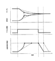
次に図2を参照して、本実施形態の内燃機関蓄圧システムを用いた場合のエアアシスト時の流量制御弁23の開度、排気圧及びタンク圧、並びにアクセル開度との関係を従来技術と比較して説明する。図2は、エアアシスト時の流量制御弁23の開度、排気圧及びタンク圧、並びにアクセル開度の夫々の関係を示すグラフである。各グラフにおいて、本実施形態の蓄圧システム20によるパラメータは実線で示され、他方、本実施形態に依らない(言い換えれば、従来の)蓄圧システムによるパラメータが点線で示される。
Next, referring to FIG. 2, the relationship between the opening degree of the
図2のグラフに示されるように、本実施形態の蓄圧システム20によれば、ECU30の制御のもと、蓄圧タンク21内のタンク圧P(x)及び排気管5内の排気圧P(Y)の圧力差ΔPに応じて、流量制御弁23の開弁速度が変化する(例えば、図2下部の流量制御弁23の開度を示すグラフを参照)。
As shown in the graph of FIG. 2, according to the
より具体的には、エアアシスト開始のタイミング(つまり、図2におけるアクセル開度の立ち上がりタイミングであって、流量制御弁開度の上昇開始タイミング)に、流量制御弁23所定の初期開弁速度で開弁された後、蓄圧タンク21内の蓄圧された排気が排気管5へと供給されることによる圧力差ΔPの減少に伴って、流量制御弁23の開弁速度が上昇するよう制御される。尚、このときの初期開弁速度は、圧力差による流量制御弁23のアクチュエータに対する過負荷が生じぬよう、比較的低速度に設定されていることが好ましく、例えば、後述する従来型の蓄圧システムにおける流量制御弁23の初期開弁速度と等しい値であっても良い。そして、流量制御弁23の開度が所定の開度に達した後に、開弁が停止される(つまり、開弁速度=0に設定される)。その後、蓄圧タンク21と排気管5とが圧力平衡状態(つまり、圧力差ΔP=0)となった状態において、流量制御弁23の閉弁が開始され、流量制御弁23が閉弁した時点でエアアシストが終了される。
More specifically, the
他方、従来型の蓄圧システムによれば、流量制御弁23は、エアアシスト開始時に設定された初期開弁速度で、所定の開度に達するまで開弁するよう制御される。尚、このときの初期開弁速度は、流量制御弁23の前後の圧力差に起因するアクチュエータへの過負荷が生じぬよう、比較的低速度に設定されている。
On the other hand, according to the conventional pressure accumulation system, the
このため、図2のグラフに示されるように、従来型の蓄圧システムと、本実施形態の蓄圧システム20とを比較した場合、典型的には、本実施形態の蓄圧システム20の流量制御弁23の方が短時間で所定開度まで開弁される。
For this reason, as shown in the graph of FIG. 2, when the conventional pressure accumulation system and the
更に、本実施形態の流量制御弁23の開弁動作によれば、比較的早く流量制御弁23の開度が増大していくため、比較的早くからより多くのエアアシスト流量を確保出来る。このため、従来型の蓄圧システムに比較して、より早く圧力差ΔPが収束し、従って応答性の良いエアアシストを実施することが出来る。
Further, according to the opening operation of the
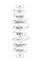
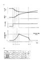
(2)基本動作
続いて、図3及び図4を参照して、より詳細な本実施形態の内燃機関蓄圧システムの動作及びその効果について説明する。図3は、本実施形態の蓄圧システム20の基本的な動作の流れを示すフローチャートである。図4(a)は、該蓄圧システム20によるエアアシスト時の流量制御弁23の開度、排気圧及びタンク圧、並びにアクセル開度の夫々の関係を示すグラフである。また、図4(b)は、ECU30による流量制御弁23の開度を制御するための、排気圧及びタンク圧の圧力差ΔP(N)と、流量制御弁23の開度θ(N)との関係を示すマップである。図4(a)に示されるグラフに示されるように、ECU30は、排気圧センサ14及びタンク圧センサ24により検出される排気圧P(Y)及びタンク圧P(X)の夫々の入力を受け、算出された圧力差ΔP(N)に基づき、流量制御弁23の開弁速度を適宜変更して、開弁動作を制御する。基本的な動作の例においては、ECU30は、図4(b)に示されるマップに基づいて流量制御弁23の開弁速度θ’(N)を決定するよう構成されている。該マップは、圧力差ΔPに応じて流量制御弁23の開弁速度が変更されるようあらかじめ定められている。
尚、図4においては、エアアシスト中の時系列をt1からt8までに便宜上分割している。
(2) Basic Operation Next, with reference to FIG. 3 and FIG. 4, a more detailed operation of the internal combustion engine accumulator system of the present embodiment and its effects will be described. FIG. 3 is a flowchart showing a basic operation flow of the
In FIG. 4, the time series during the air assist is divided for convenience from t1 to t8.
図3に示されるように、ドライバの操作などにより、蓄圧システム20を備えるエンジン1が搭載される車両の加速が実施されること(図3のステップ:S101)と相前後して、流量制御弁23の開弁速度がECU30によりθ’(0)に設定されることで、流量制御弁23の開弁が開始され、エアアシストが開始される(図3のステップ:S102及び図4のt0)。
As shown in FIG. 3, the flow control valve is executed in tandem with the acceleration of the vehicle on which the
続いて、ECU30は、図4(b)のマップを参照しながら、圧力差ΔP(N)に応じて流量制御弁23の開弁速度を適宜決定し直しつつ、開弁動作を実施する(図3のステップ:S103及び図4のt1からt3)。このとき、Nは時系列t1からt8の夫々に対応することを示す数値であって、例えばΔP(1)とは時間t1のときの圧力差を示す趣旨である。ここに、圧力差ΔP(N)は、エアアシストの実施に伴って次第に減少していくことから、ΔP(1)≧ΔP(2)≧ΔP(3)との関係が成り立つ。このとき、マップにより設定される流量制御弁23の開度は、時間の経過に伴って開弁されることから、少なくともθ(1)<θ(2)<θ(3)となる。また、図4(a)のグラフに示されるように開弁速度は、圧力差ΔPの減少に伴って上昇するよう設定されるため、θ’(0)<θ’(1)<θ’(2)との関係が成り立つ。
Subsequently, the
そして、流量制御弁23の開度があらかじめ設定される最大開度θMaxに達した場合(図3のステップ:S104:Yes及び図4のt3であって、つまりθ(3)=θMax)、ECU30は流量制御弁23の開弁を停止する(言い換えれば、流量制御弁23の開弁速度θ’(3)=0とする)。このときの最大開度θMaxとは、典型的には、一連のエアアシスト動作における流量制御弁23の最大開度を示す趣旨であり、必ずしも流量制御弁23の全開位置に相当する開度であるとは限らない。尚、最大開度θMaxは、好適なエアアシストを実施可能な範囲で適宜決定されて良い。
When the opening degree of the
流量制御弁23の開度が最大開度θMaxに到達した後、流量制御弁23が停止した状態、つまり最大開度θMaxでのエアアシストが継続される(図3のステップS105図4のt3からt7の間)。このため、流量制御弁23の開度θ(3)からθ(7)は、最大開度θMaxに等しく、流量制御弁23の開弁速度θ’(3)からθ’(6)は、0となる。
After the opening degree of the
エアアシストの実施に伴って圧力差ΔPが減少し、ΔP=0となった場合(図3のステップ:S106:Yes及び図4のt7)、ECU30は、流量制御弁23の閉弁を開始する(図3のステップ:S107)。言い換えれば、ECU30は、マップに従い、流量制御弁23の開弁速度をθ’7(<0)に決定する。そして、流量制御弁23の開度が0となった時点で(図3のステップ:S108及び図4のt8)、流量制御弁23の開弁速度を0とし、エアアシストを終了する。
When the pressure difference ΔP decreases with the implementation of air assist and becomes ΔP = 0 (step in FIG. 3: S106: Yes and t7 in FIG. 4), the
以上説明したように、本実施形態の蓄圧システム20によれば、比較的低速での開弁を開始することで流量制御弁23の前後における大きな圧力差に起因する開弁時の負荷を好適に低減させることが可能となる。このため、過負荷によるアクチュエータの脱調などの不具合を好適に抑制可能な開弁制御が可能となる。また、エアアシストの実施による圧力差の減少と共に、流量制御弁23の開弁速度を上昇させていくことで、比較的早い時点で流量制御弁23の開弁を実現出来るため、より応答性の良いエアアシストの実施が可能となる。
As described above, according to the
尚、図4(b)のマップでは、圧力差ΔP(N)並びに、流量制御弁23の開度θ(N)及び開弁速度θ’(N)が設定されているが、マップの態様はこれに限られず、上述の流量制御弁23の一連の動作の制御を実施可能な態様であれば、その他のパラメータより構成されるものであっても良い。
In the map of FIG. 4B, the pressure difference ΔP (N), the opening degree θ (N) of the
(3)変形動作例
続いて、図5及び図6を参照して、本実施形態の蓄圧システム20の変形動作例及びその効果について説明する。図5は、本実施形態の蓄圧システム20の変形動作例の流れを示すフローチャートである。尚、該フローチャートにおいて、図3に示される基本動作の流れと同等の動作を行うフローについては同一の付番を付している。図6(a)は、本変形動作例における、蓄圧システム20によるエアアシスト時の流量制御弁23の開度、排気圧及びタンク圧、並びにアクセル開度の夫々の関係を示すグラフであり、図4(b)は、このとき用いられるマップである。
(3) Modified Operation Example Next, with reference to FIG. 5 and FIG. 6, a modified operation example of the
本変形動作例においては、上述の基本動作と同様、車両の加速開始と相前後してエアアシストが開始され、流量制御弁23の開弁が開始される(図5のステップ:S103からS103及び図6のt0からt3)。その後、流量制御弁23の開度が最大開度θMaxに到達した場合(図5のステップ:S104:Yes及び図6のt3)、ECU30は、マップに従い、流量制御弁23の開弁速度をθ'3(<0)に変更して閉弁を開始する(図5のステップ:S201)。このときの流量制御弁23の閉弁速度は、エアアシストが中断されない程度の比較的低速であることが好ましい。
In this modified operation example, as in the basic operation described above, the air assist is started before and after the acceleration of the vehicle is started, and the
その後、流量制御弁23の閉弁と同時にエアアシストは継続され、圧力差ΔPは減少し、次第に0へと収束していく。
Thereafter, the air assist is continued simultaneously with the closing of the flow
圧力差ΔPが0となった時点で(図5のステップ:S106:Yes及び図6のt4)、ECU30は、マップに従い流量制御弁23の開弁速度をθ’4(<0)に変更して、流量制御弁23を全閉位置まで切り替える(図3のステップ:S202及び図6のt4からt5)。このとき、流量制御弁23の開弁速度θ’4は、比較的高速であり、少なくとも速度の絶対値において、θ’4はθ’3より大きいとの関係が成り立つ。そして、流量制御弁23の開度が0となった時点で(図5のステップ:S108及び図6のt5)エアアシストを終了する。
When the pressure difference ΔP becomes 0 (step in FIG. 5: S106: Yes and t4 in FIG. 6), the
以上説明したように、蓄圧システム20の変形動作例によれば、上述した基本動作と同様、流量制御弁23の開弁を比較的低い開弁速度で開始し、圧力差の減少に応じて次第に上昇させていくことで、過負荷によるアクチュエータの脱調などの不具合を好適に抑制し、且つ比較的早い時点で流量制御弁23の開弁を実現出来る。
As described above, according to the modified operation example of the
更に、エアアシスト中に徐々に流量制御弁23の閉弁を実施することで、エアアシスト終了時における流量制御弁23の閉弁量が減少する。このため、一般的に比較的早い速度で実施されるエアアシスト終了時の流量制御弁23の閉弁動作において、大きな閉弁量を急激に閉弁させる状況を回避可能となり、急激な閉弁に伴うアクチュエータの脱調などの不具合を好適に抑制することが出来る。
Further, by gradually closing the flow
尚、本変形動作例において、特に記述しない点については、上述の基本動作と同様の構成であって良い。 Note that in this modified operation example, the configuration that is not particularly described may be the same as the basic operation described above.
本発明は、上述した実施例に限られるものではなく、特許請求の範囲及び明細書全体から読み取れる発明の要旨或いは思想に反しない範囲で適宜変更可能であり、そのような変更を伴う内燃機関蓄圧システムもまた本発明の技術的範囲に含まれるものである。 The present invention is not limited to the above-described embodiments, and can be appropriately changed without departing from the gist or concept of the invention that can be read from the claims and the entire specification. The system is also included in the technical scope of the present invention.
1 エンジン、
4 吸気通路、
4a 吸気マニホールド
5 排気通路、
5a 排気マニホールド
7b タービン、
10 廃棄遮断弁、
11 EGR通路、
13 EGR弁、
14 排気圧センサ、
15 排気バイパス通路
16 排気バイパス弁、
20 蓄圧システム、
21 蓄圧タンク、
22 ガス通路、
23 流量制御弁、
24 タンク圧センサ、
30 エンジンコントロールユニット(ECU)
1 engine,
4 Intake passage,
10 Waste shut-off valve,
11 EGR passage,
13 EGR valve,
14 Exhaust pressure sensor,
15
20 pressure accumulation system,
21 pressure storage tank,
22 Gas passageway,
23 Flow control valve,
24 tank pressure sensor,
30 Engine control unit (ECU)
Claims (7)
前記排気管、前記蓄圧タンク及び前記所定の供給先を連通するとともに、前記排気管内のガスを前記蓄圧タンクへと供給し、前記蓄圧タンク内のガスを前記所定の供給先へと供給するガス通路と、
前記ガス通路における前記蓄圧タンクと前記所定の供給先との間に設けられ、全開する全開位置と全閉する全閉位置との間で開度を調整可能な流量制御弁と、
前記流量制御弁の開閉動作を制御する制御手段とを備え、
前記制御手段は、前記排気管内の排気圧及び前記蓄圧タンク内のタンク圧に基づいて、前記流量制御弁の開弁速度を決定することを特徴とする内燃機関蓄圧システム。 An internal combustion engine accumulator equipped with an accumulator tank capable of accumulating exhaust pressure by closing an exhaust shutoff valve provided in an exhaust pipe communicating with an internal combustion engine mounted on a vehicle and supplying the exhaust pressure to a predetermined supply destination A system,
A gas passage that communicates the exhaust pipe, the pressure accumulation tank, and the predetermined supply destination, supplies gas in the exhaust pipe to the pressure accumulation tank, and supplies gas in the pressure accumulation tank to the predetermined supply destination When,
A flow rate control valve provided between the pressure accumulation tank in the gas passage and the predetermined supply destination, the flow rate control valve capable of adjusting the opening degree between a fully open position to be fully opened and a fully closed position to be fully closed;
Control means for controlling the opening and closing operation of the flow control valve,
The internal combustion engine pressure accumulation system according to claim 1, wherein the control means determines a valve opening speed of the flow rate control valve based on an exhaust pressure in the exhaust pipe and a tank pressure in the pressure accumulation tank.
Priority Applications (1)
| Application Number | Priority Date | Filing Date | Title |
|---|---|---|---|
| JP2009068347A JP2010222995A (en) | 2009-03-19 | 2009-03-19 | Internal combustion engine accumulator system |
Applications Claiming Priority (1)
| Application Number | Priority Date | Filing Date | Title |
|---|---|---|---|
| JP2009068347A JP2010222995A (en) | 2009-03-19 | 2009-03-19 | Internal combustion engine accumulator system |
Publications (1)
| Publication Number | Publication Date |
|---|---|
| JP2010222995A true JP2010222995A (en) | 2010-10-07 |
Family
ID=43040472
Family Applications (1)
| Application Number | Title | Priority Date | Filing Date |
|---|---|---|---|
| JP2009068347A Pending JP2010222995A (en) | 2009-03-19 | 2009-03-19 | Internal combustion engine accumulator system |
Country Status (1)
| Country | Link |
|---|---|
| JP (1) | JP2010222995A (en) |
Citations (4)
| Publication number | Priority date | Publication date | Assignee | Title |
|---|---|---|---|---|
| JPS6157138U (en) * | 1984-09-19 | 1986-04-17 | ||
| JP2001098958A (en) * | 1999-10-01 | 2001-04-10 | Aisan Ind Co Ltd | Throttle valve device and control method thereof |
| JP2001114085A (en) * | 1999-10-18 | 2001-04-24 | Toyota Motor Corp | Hydraulic pressure control device for brake system |
| WO2009031629A1 (en) * | 2007-09-05 | 2009-03-12 | Toyota Jidosha Kabushiki Kaisha | Internal combustion engine with turbocharger |
-
2009
- 2009-03-19 JP JP2009068347A patent/JP2010222995A/en active Pending
Patent Citations (4)
| Publication number | Priority date | Publication date | Assignee | Title |
|---|---|---|---|---|
| JPS6157138U (en) * | 1984-09-19 | 1986-04-17 | ||
| JP2001098958A (en) * | 1999-10-01 | 2001-04-10 | Aisan Ind Co Ltd | Throttle valve device and control method thereof |
| JP2001114085A (en) * | 1999-10-18 | 2001-04-24 | Toyota Motor Corp | Hydraulic pressure control device for brake system |
| WO2009031629A1 (en) * | 2007-09-05 | 2009-03-12 | Toyota Jidosha Kabushiki Kaisha | Internal combustion engine with turbocharger |
Similar Documents
| Publication | Publication Date | Title |
|---|---|---|
| EP2360362B1 (en) | Pressure accumulation system for internal combustion engine | |
| CN101389845B (en) | Control apparatus of internal combustion engine and control method of internal combustion engine | |
| CN102124200B (en) | Control devices for internal combustion engines | |
| CN103547781B (en) | Internal combustion engine control apparatus | |
| JP5649343B2 (en) | Intake throttle control method for internal combustion engine | |
| JP5321729B2 (en) | Vehicle comprising an internal combustion engine with a valve stop mechanism | |
| CN101457689A (en) | Method for operating a compressor | |
| JP2010229901A (en) | Control device for an internal combustion engine with a supercharger | |
| JP2010190052A (en) | Supercharging system for internal combustion engine | |
| JP2014240206A (en) | Vehicle control device and control method | |
| JP4953100B2 (en) | Turbocharged internal combustion engine | |
| JP2008157139A (en) | Internal combustion engine with a supercharger | |
| JP5849634B2 (en) | Control device for turbocharged diesel engine | |
| JP2010222995A (en) | Internal combustion engine accumulator system | |
| JP5808152B2 (en) | Control device for internal combustion engine | |
| JP4923941B2 (en) | Supercharging control device | |
| JP5682163B2 (en) | Supercharging device with supercharging assistance and discharge control valve | |
| JP2011007066A (en) | Internal combustion engine accumulator system | |
| JP4735436B2 (en) | Supercharging system for internal combustion engines | |
| JP2008215105A (en) | Diesel engine | |
| JP2010185411A (en) | Pressure accumulation system for internal combustion engine | |
| JP4499592B2 (en) | Exhaust brake device for vehicle | |
| JP5771911B2 (en) | Automatic stop / restart system for compression ignition internal combustion engine | |
| JP2013174219A (en) | Internal combustion engine | |
| JP5906724B2 (en) | Control device for turbocharged engine |
Legal Events
| Date | Code | Title | Description |
|---|---|---|---|
| A621 | Written request for application examination |
Free format text: JAPANESE INTERMEDIATE CODE: A621 Effective date: 20111221 |
|
| A977 | Report on retrieval |
Free format text: JAPANESE INTERMEDIATE CODE: A971007 Effective date: 20130124 |
|
| A131 | Notification of reasons for refusal |
Free format text: JAPANESE INTERMEDIATE CODE: A131 Effective date: 20130219 |
|
| A02 | Decision of refusal |
Free format text: JAPANESE INTERMEDIATE CODE: A02 Effective date: 20130702 |