JP2010229902A - Engine blower - Google Patents
Engine blower Download PDFInfo
- Publication number
- JP2010229902A JP2010229902A JP2009078679A JP2009078679A JP2010229902A JP 2010229902 A JP2010229902 A JP 2010229902A JP 2009078679 A JP2009078679 A JP 2009078679A JP 2009078679 A JP2009078679 A JP 2009078679A JP 2010229902 A JP2010229902 A JP 2010229902A
- Authority
- JP
- Japan
- Prior art keywords
- frame
- engine
- blower
- foamed resin
- filled
- Prior art date
- Legal status (The legal status is an assumption and is not a legal conclusion. Google has not performed a legal analysis and makes no representation as to the accuracy of the status listed.)
- Pending
Links
- 239000011347 resin Substances 0.000 claims abstract description 33
- 229920005989 resin Polymers 0.000 claims abstract description 33
- NJPPVKZQTLUDBO-UHFFFAOYSA-N novaluron Chemical compound C1=C(Cl)C(OC(F)(F)C(OC(F)(F)F)F)=CC=C1NC(=O)NC(=O)C1=C(F)C=CC=C1F NJPPVKZQTLUDBO-UHFFFAOYSA-N 0.000 claims description 9
- 238000000071 blow moulding Methods 0.000 claims description 7
- 239000006260 foam Substances 0.000 claims description 6
- JOYRKODLDBILNP-UHFFFAOYSA-N Ethyl urethane Chemical compound CCOC(N)=O JOYRKODLDBILNP-UHFFFAOYSA-N 0.000 claims description 5
- 239000007787 solid Substances 0.000 abstract description 4
- 239000000463 material Substances 0.000 description 5
- 238000005187 foaming Methods 0.000 description 3
- 239000002828 fuel tank Substances 0.000 description 3
- 230000000694 effects Effects 0.000 description 2
- 229920001971 elastomer Polymers 0.000 description 2
- 239000000446 fuel Substances 0.000 description 2
- 238000000034 method Methods 0.000 description 2
- 230000004048 modification Effects 0.000 description 2
- 238000012986 modification Methods 0.000 description 2
- 239000005060 rubber Substances 0.000 description 2
- 244000025254 Cannabis sativa Species 0.000 description 1
- 239000004743 Polypropylene Substances 0.000 description 1
- 238000007664 blowing Methods 0.000 description 1
- 238000004140 cleaning Methods 0.000 description 1
- 230000007423 decrease Effects 0.000 description 1
- 238000010586 diagram Methods 0.000 description 1
- 238000006073 displacement reaction Methods 0.000 description 1
- 229920006248 expandable polystyrene Polymers 0.000 description 1
- 239000004088 foaming agent Substances 0.000 description 1
- 238000001746 injection moulding Methods 0.000 description 1
- 239000000203 mixture Substances 0.000 description 1
- -1 polypropylene Polymers 0.000 description 1
- 229920001155 polypropylene Polymers 0.000 description 1
Images


Landscapes
- Structures Of Non-Positive Displacement Pumps (AREA)
Abstract
Description
本発明は、エンジンブロワに関する。 The present invention relates to an engine blower.
従来、エンジンブロワの例えば背負い式のものは、エンジン、遠心式送風機、燃料タンク等の主要な構成部分が、落下衝撃の吸収性のよいブロー成形で形成された側面視L字形状のフレームに載置され、作業者がフレームごと背負って刈草、枯葉等の吹き寄せ作業を行なっている(例えば特許文献1)。
しかしながら、ブロー成形フレームのL字形状の屈曲部分は、中空構造である分、例えばリブ構造を有した射出成形のフレームの屈曲部分に比べて剛性が低いため、エンジンの振動によるフレームの共振の振動レベルが大きくなり、作業者に不快感を与えるという問題があった。 However, the L-shaped bent portion of the blow-molded frame has a lower rigidity than the bent portion of the injection-molded frame having a rib structure, for example, because of the hollow structure. There was a problem that the level was increased and the worker was uncomfortable.
ブロー成形フレームのL字形状の屈曲部分の剛性を上げる方法として、材料であるパリソンの目付け重量を増やして肉厚を厚くすることが考えられる。しかし、パリソンの肉厚を厚くしても、ブロー成形の性質上、屈曲部分の肉厚のみを厚くしづらいため、フレームの肉厚が全体的に厚くなってしまい、フレームの重量が大きくなってしまう。 As a method for increasing the rigidity of the L-shaped bent portion of the blow-molded frame, it is conceivable to increase the weight of the parison, which is a material, to increase the wall thickness. However, even if the wall thickness of the parison is increased, it is difficult to increase only the thickness of the bent portion due to the nature of blow molding, so the overall thickness of the frame increases and the weight of the frame increases. End up.
本発明の目的は、ブロー成形フレームの剛性を部分的に大きくすることによって、フレームの共振の振動レベルを小さくでき、またフレームの共振周波数がずれて共振しにくくでき、かつ重量の増加を抑制できるエンジンブロワを提供することにある。 The object of the present invention is to partially increase the rigidity of the blow molded frame, thereby reducing the vibration level of the resonance of the frame, making it difficult to resonate by shifting the resonance frequency of the frame, and suppressing an increase in weight. To provide an engine blower.
本発明に係るエンジンブロワは、エンジン、前記エンジンによって駆動されるファン、および前記ファンが内部に収容されるボリュートケースを備えて構成されたブロワ本体と、前記ブロワ本体に接続された風管と、前記ブロワ本体を支持する背負い用のフレームとを備え、前記フレームは、ブロー成形で形成されているとともに、内部に中空部を有し、前記中空部には発泡樹脂が充填されていることを特徴とする。 An engine blower according to the present invention includes an engine, a fan driven by the engine, a blower body configured to include a volute case in which the fan is housed, a wind pipe connected to the blower body, A frame for supporting the blower body, the frame being formed by blow molding, having a hollow portion therein, and the hollow portion being filled with foamed resin. And
本発明に係るエンジンブロワでは、前記フレームが、使用者の背中に当接される背当て部と、前記背当て部に直交する方向に延びた架台部を有したL字形状であり、前記発泡樹脂は、L字形状の屈曲部分に対応した前記中空部にのみ充填されていることを特徴とする。 In the engine blower according to the present invention, the frame has an L shape having a back support portion that comes into contact with a user's back and a pedestal portion extending in a direction orthogonal to the back support portion, and the foam The resin is filled only in the hollow portion corresponding to the L-shaped bent portion.
本発明に係るエンジンブロワでは、前記中空部が背当て部および前記架台部に跨って設けられていることを特徴とする。 The engine blower according to the present invention is characterized in that the hollow portion is provided across the backrest portion and the pedestal portion.
本発明に係るエンジンブロワでは、前記発泡樹脂が発泡ウレタンであることを特徴とする。 In the engine blower according to the present invention, the foamed resin is urethane foam.
本発明によれば、フレームの中空部は、発泡樹脂が充填されて中実構造に近くなっているため、発泡樹脂を注入しない場合に比べてフレームの剛性(ばね定数)を大きくできる。つまり、剛性を大きくすることで、フレームの共振周波数がずれ、エンジンに対して共振しにくくでき、エンジンの振動によって発生するフレームの共振の振動レベルを小さくできる。また、フレームの材料自体でフレームを中実構造にする射出成形に比べてフレームの重量の増加を抑制できる。 According to the present invention, since the hollow portion of the frame is close to a solid structure filled with the foamed resin, the rigidity (spring constant) of the frame can be increased as compared with the case where the foamed resin is not injected. In other words, by increasing the rigidity, the resonance frequency of the frame is shifted and it is difficult to resonate with the engine, and the vibration level of the resonance of the frame caused by the vibration of the engine can be reduced. Further, the increase in the weight of the frame can be suppressed as compared with the injection molding in which the frame material itself is a solid structure.
L字形状の屈曲部分に対応した中空部にのみ発泡樹脂を充填した場合には、発泡樹脂の余分な充填をなくすことができ、フレームの重量の増加を最小限にできる。
発泡樹脂が充填される中空部を背当て部および架台部に跨って形成した場合には、フレームの屈曲部への発泡樹脂の充填を1回で行え、充填作業を容易にできる。
発泡樹脂を発泡ウレタンとすることにより、発泡ウレタンの発泡倍率を容易に調整でき、フレームの剛性を目標とする大きさに確実に大きくできる。
When the foamed resin is filled only in the hollow portion corresponding to the bent portion of the L-shape, the extra filling of the foamed resin can be eliminated, and the increase in the weight of the frame can be minimized.
In the case where the hollow portion filled with the foamed resin is formed across the backrest portion and the pedestal portion, the foamed resin can be filled into the bent portion of the frame at once, and the filling operation can be facilitated.
By using urethane foam as the foamed resin, the expansion ratio of urethane foam can be easily adjusted, and the rigidity of the frame can be reliably increased to a target size.
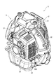
以下、本発明の一実施形態を図面に基づいて説明する。なお、図1は、エンジンブロワ1を背面側(作業者に対して背面側)から見た斜視図、図2は、エンジンブロワ1を正面側(作業者に対して正面側)から見た斜視図、図3は、フレーム2を示す背面図、図4は、図3中の線IV−IVでフレーム2を切断した場合の断面図である。
エンジンブロワ1は、図1および図2に示すように、フレーム2と、フレーム2に支持されたブロワ本体3と、ブロワ本体3に接続された図示しない風管とを備えている。
Hereinafter, an embodiment of the present invention will be described with reference to the drawings. 1 is a perspective view of the engine blower 1 viewed from the back side (back side with respect to the worker), and FIG. 2 is a perspective view of the engine blower 1 viewed from the front side (front side with respect to the worker). 3 is a rear view showing the
As shown in FIGS. 1 and 2, the engine blower 1 includes a
フレーム2は、図4に示すように、背負いベルトが取り付けられて使用者の背中に当接される背当て部21と、背当て部21に直交する方向に延びた架台部22とを備え、側面視L字形状に形成されている。背当て部21の側方には、図2に示すように、操作ハンドル4が回動自在に取り付けられている。作業時には、この操作ハンドル4を正面側(図2中左側)に倒し、当該操作ハンドル4を操作することで、ブロワ本体3のエンジン31の出力調整を行う。
As shown in FIG. 4, the
ブロワ本体3は、エンジン31と、エンジン31により駆動される図示しないファンと、エンジン31に取り付けられるとともに、ファンを収容するボリュートケース32と、燃料タンク33と、燃料タンク33からの燃料および吸入空気により混合気を生成するキャブレタ34と、エンジン31の音を消音し、排気ガスを外部へ排出するマフラー35とを備えている。
The
そして、ブロワ本体3は、ボリュートケース32下部に設けられた左右の防振ゴム36A、36Bを介して架台部22に支持されるとともに、ボリュートケース32上部に設けられた図示しない防振ゴムを介して背当て部21に連結されることによって、フレーム2に対して3点で支持されている。このようなブロワ本体3では、エンジン31によりファンが駆動され、ファンにより圧送空気が生成されると、圧送空気は、ボリュートケース32から当該ボリュートケース32に接続された風管に送られ、風管から噴出することとなる。
The
以下は、本実施形態のエンジンブロワ1での特徴的構成について詳説する。
本実施形態のフレーム2は、ブロー成形によって形成され、複数の中空部23を備えている。中空部23の内、背当て部21と架台部22に跨る部分に形成された左右の中空部23A、23Bには、発泡樹脂24が充填されている。
The following is a detailed description of the characteristic configuration of the engine blower 1 of the present embodiment.
The
発泡樹脂24としては、本実施形態では発泡倍率を容易に調整可能な発泡ウレタンを使用しているが、その他として発泡ポリスチレンや発泡ポリプロピレンなどを適用できる。発泡樹脂24の充填量は、フレーム2が共振しにくくなる程度にフレーム2の剛性を上げられる量であればよく、本実施形態では、発泡樹脂24の発泡倍率との積が中空部23A、23Bの容積と略等しくなる体積である。また、発泡樹脂24は、発泡過程でフレーム2に密着する。
As the
このような発泡樹脂24は、フレーム2のブロー成形の後に充填される。つまり、フレーム2のブロー成形の後、フレーム2の中空部23A、23Bに対応した部位に内外を連通させる図示しない充填孔を設け、この充填孔に充填ノズルを差し入れて発泡樹脂材料を充填する。充填された発泡樹脂材料は、基材中に混入された発泡剤により発泡し、発泡樹脂24として充填される。
Such
以上のような構成において、フレーム2の屈曲部分に対応した中空部23A、23B内には、発泡樹脂24が充填されているため、屈曲部分が中実構造に近くなり、発泡樹脂24を注入しない場合に比べて当該屈曲部分の剛性(ばね定数)を大きくできる。つまり、剛性を大きくすることで、フレーム2の共振周波数をずらしてエンジン31対して共振しにくくでき、エンジンの振動によって発生するフレーム2の共振の振動レベルを小さくできる。また、当該屈曲部分にのみ発泡樹脂24が注入され、かつ発泡樹脂は体積の割に軽量であるから、フレーム2の重量の増加を最小限にできる。
In the configuration as described above, since the
次に、フレーム2の振動に関係する実験結果を以下に示す。
図5は、本実施形態の効果を示すフレーム2の剛性(ばね定数)を示す図である。フレーム2の背当て部21を固定し、架台部22の先端部に下向きの荷重をかけ、架台部22の先端部が底面側へ変位した量を測定することによってフレーム2の剛性(ばね定数)を測定した。図5から、発泡樹脂24を充填することによってフレーム2の剛性(ばね定数)が大きくなったことがわかる。
Next, experimental results related to the vibration of the
FIG. 5 is a diagram showing the rigidity (spring constant) of the
そして、図6は、本実施形態の効果を示すエンジン回転数毎のフレームの振動レベルを示す図である。図6から、フレーム2の剛性が上がると、フレーム2の振動レベルが下がることが確認された。特に作業時に多用される回転数域A(3600〜3800[rpm])あたりでの振動レベルが確実に低減されていることがわかる。これは、剛性が向上することにより、フレーム2の共振周波数がずれたことによるものと考えられる。
〔実施形態の変形〕
なお、本発明は前述の実施形態に限定されるものではなく、本発明の目的を達成できる範囲での変形、改良等は本発明に含まれるものである。
例えば、本実施形態のフレーム2には、側面視L字形状を用いたが、本発明のフレームとしては、L字形状である必要はなく、背負ってブロワ本体3を支持できる形状であればよい。つまり、フレームでの支持構造や、フレームの全体形状等を勘案し、剛性を確実に向上させて振動レベルを下げることのできる中空部に対して発泡樹脂を充填すればよい。
And FIG. 6 is a figure which shows the vibration level of the flame | frame for every engine speed which shows the effect of this embodiment. From FIG. 6, it was confirmed that when the rigidity of the
[Modification of Embodiment]
It should be noted that the present invention is not limited to the above-described embodiments, and modifications, improvements, and the like within the scope that can achieve the object of the present invention are included in the present invention.
For example, the
本発明は、公園等の野外清掃に用いられるエンジンブロワに利用できる。 The present invention can be used for an engine blower used for outdoor cleaning of a park or the like.
1…エンジンブロワ、2…フレーム、3…ブロワ本体、21…背当て部、22…架台部、23、23A、23B…中空部、24…発泡樹脂、31…エンジン、32…ボリュートケース。 DESCRIPTION OF SYMBOLS 1 ... Engine blower, 2 ... Frame, 3 ... Blower main body, 21 ... Backrest part, 22 ... Mount part, 23, 23A, 23B ... Hollow part, 24 ... Foam resin, 31 ... Engine, 32 ... Volute case.
Claims (4)
前記ブロワ本体に接続された風管と、
前記ブロワ本体を支持する背負い用のフレームとを備え、
前記フレームは、ブロー成形で形成されているとともに、内部に中空部を有し、
前記中空部には発泡樹脂が充填されている
ことを特徴とするエンジンブロワ。 A blower body comprising an engine, a fan driven by the engine, and a volute case in which the fan is housed;
A wind pipe connected to the blower body;
And a frame for supporting the blower body,
The frame is formed by blow molding and has a hollow portion inside,
An engine blower characterized in that the hollow portion is filled with foamed resin.
前記フレームは、使用者の背中に当接される背当て部と、前記背当て部に直交する方向に延びた架台部を有したL字形状であり、
前記発泡樹脂は、L字形状の屈曲部分に対応した前記中空部にのみ充填されている
ことを特徴とするエンジンブロワ。 The engine blower according to claim 1, wherein
The frame has an L shape having a back support portion that comes into contact with a user's back and a pedestal portion extending in a direction orthogonal to the back support portion.
The engine blower, wherein the foamed resin is filled only in the hollow portion corresponding to an L-shaped bent portion.
前記中空部は、前記背当て部および前記架台部に跨って設けられている
ことを特徴とするエンジンブロワ。 The engine blower according to claim 2,
The hollow portion is provided across the backrest portion and the pedestal portion. Engine blower, wherein
前記発泡樹脂は、発泡ウレタンである
ことを特徴とするエンジンブロワ。 The engine blower according to any one of claims 1 to 3,
The engine blower, wherein the foamed resin is urethane foam.
Priority Applications (1)
| Application Number | Priority Date | Filing Date | Title |
|---|---|---|---|
| JP2009078679A JP2010229902A (en) | 2009-03-27 | 2009-03-27 | Engine blower |
Applications Claiming Priority (1)
| Application Number | Priority Date | Filing Date | Title |
|---|---|---|---|
| JP2009078679A JP2010229902A (en) | 2009-03-27 | 2009-03-27 | Engine blower |
Publications (1)
| Publication Number | Publication Date |
|---|---|
| JP2010229902A true JP2010229902A (en) | 2010-10-14 |
Family
ID=43045957
Family Applications (1)
| Application Number | Title | Priority Date | Filing Date |
|---|---|---|---|
| JP2009078679A Pending JP2010229902A (en) | 2009-03-27 | 2009-03-27 | Engine blower |
Country Status (1)
| Country | Link |
|---|---|
| JP (1) | JP2010229902A (en) |
Citations (4)
| Publication number | Priority date | Publication date | Assignee | Title |
|---|---|---|---|---|
| JPS63198498U (en) * | 1987-06-09 | 1988-12-21 | ||
| JP2001041196A (en) * | 1999-07-26 | 2001-02-13 | Matsushita Electric Ind Co Ltd | Impeller for blower |
| JP2002155899A (en) * | 2000-11-21 | 2002-05-31 | Kioritz Corp | Backpack stand |
| JP2002173034A (en) * | 2000-12-06 | 2002-06-18 | Koyo Seiko Co Ltd | Mounting structure for power steering device |
-
2009
- 2009-03-27 JP JP2009078679A patent/JP2010229902A/en active Pending
Patent Citations (4)
| Publication number | Priority date | Publication date | Assignee | Title |
|---|---|---|---|---|
| JPS63198498U (en) * | 1987-06-09 | 1988-12-21 | ||
| JP2001041196A (en) * | 1999-07-26 | 2001-02-13 | Matsushita Electric Ind Co Ltd | Impeller for blower |
| JP2002155899A (en) * | 2000-11-21 | 2002-05-31 | Kioritz Corp | Backpack stand |
| JP2002173034A (en) * | 2000-12-06 | 2002-06-18 | Koyo Seiko Co Ltd | Mounting structure for power steering device |
Similar Documents
| Publication | Publication Date | Title |
|---|---|---|
| US9538711B2 (en) | Backpack working machine | |
| JP2501215Y2 (en) | Backpack type power working machine | |
| JP6068348B2 (en) | Vehicle seat device | |
| JP2008002310A (en) | Back blower | |
| US10405659B2 (en) | Folding chair armrest with acoustic enhancing cell phone holder | |
| CN102743127B (en) | Suction device and electric dust collector | |
| BRPI0901990A2 (en) | generator engine | |
| JP5466666B2 (en) | Sheet structure | |
| JP2002155899A (en) | Backpack stand | |
| JP5369767B2 (en) | Cushion body manufacturing method | |
| JP2004166064A (en) | Inner panel and speaker | |
| CN204131272U (en) | A kind of tail fixing device of suction cleaner using motor | |
| JP2012118148A (en) | Absorber mounting structure | |
| JP2005181481A (en) | Noise reduction device | |
| JP2019040147A (en) | Sound absorbing material mounting structure | |
| JP4727608B2 (en) | Intake silencer and silencer method | |
| JP2003170751A (en) | Silencer for fuel tank | |
| KR101343196B1 (en) | Hand drying device | |
| JP2007253332A (en) | Fixing structure of elastic resin sheet and fixing method of elastic resin sheet | |
| US20060293399A1 (en) | Electrical apparatus with a foamed stiffener and manufacturing method thereof | |
| JP2003083186A (en) | Noise reduced duct | |
| JP7294299B2 (en) | engine hood | |
| CN217792860U (en) | Handle assembly of cleaning device and cleaning device | |
| CN223364210U (en) | Box and sound production | |
| KR100957351B1 (en) | Intake discharge sound quality tuning structure of vehicle |
Legal Events
| Date | Code | Title | Description |
|---|---|---|---|
| A621 | Written request for application examination |
Effective date: 20120326 Free format text: JAPANESE INTERMEDIATE CODE: A621 |
|
| A977 | Report on retrieval |
Effective date: 20130128 Free format text: JAPANESE INTERMEDIATE CODE: A971007 |
|
| A131 | Notification of reasons for refusal |
Effective date: 20130205 Free format text: JAPANESE INTERMEDIATE CODE: A131 |
|
| A521 | Written amendment |
Effective date: 20130312 Free format text: JAPANESE INTERMEDIATE CODE: A523 |
|
| A02 | Decision of refusal |
Free format text: JAPANESE INTERMEDIATE CODE: A02 Effective date: 20130409 |