JP2010239727A - Ac generator for vehicle and generator motor device for vehicle - Google Patents
Ac generator for vehicle and generator motor device for vehicle Download PDFInfo
- Publication number
- JP2010239727A JP2010239727A JP2009083984A JP2009083984A JP2010239727A JP 2010239727 A JP2010239727 A JP 2010239727A JP 2009083984 A JP2009083984 A JP 2009083984A JP 2009083984 A JP2009083984 A JP 2009083984A JP 2010239727 A JP2010239727 A JP 2010239727A
- Authority
- JP
- Japan
- Prior art keywords
- rotor
- stator
- rectifier
- generator
- cooling air
- Prior art date
- Legal status (The legal status is an assumption and is not a legal conclusion. Google has not performed a legal analysis and makes no representation as to the accuracy of the status listed.)
- Pending
Links
- 238000001816 cooling Methods 0.000 claims abstract description 60
- 239000004020 conductor Substances 0.000 claims abstract description 25
- 238000004804 winding Methods 0.000 claims description 33
- 238000001514 detection method Methods 0.000 claims description 21
- 239000012774 insulation material Substances 0.000 abstract 1
- 239000011347 resin Substances 0.000 description 19
- 229920005989 resin Polymers 0.000 description 19
- 230000002093 peripheral effect Effects 0.000 description 14
- 229910052782 aluminium Inorganic materials 0.000 description 13
- XAGFODPZIPBFFR-UHFFFAOYSA-N aluminium Chemical compound [Al] XAGFODPZIPBFFR-UHFFFAOYSA-N 0.000 description 13
- 229910000831 Steel Inorganic materials 0.000 description 7
- 238000009413 insulation Methods 0.000 description 7
- 239000000463 material Substances 0.000 description 7
- 239000010959 steel Substances 0.000 description 7
- 210000000078 claw Anatomy 0.000 description 6
- 230000000694 effects Effects 0.000 description 6
- 239000000758 substrate Substances 0.000 description 6
- 229910052751 metal Inorganic materials 0.000 description 5
- 239000002184 metal Substances 0.000 description 5
- 230000007935 neutral effect Effects 0.000 description 5
- 239000011248 coating agent Substances 0.000 description 4
- 238000000576 coating method Methods 0.000 description 4
- 238000000034 method Methods 0.000 description 4
- 230000004907 flux Effects 0.000 description 3
- 239000012212 insulator Substances 0.000 description 3
- 238000000465 moulding Methods 0.000 description 3
- 238000009423 ventilation Methods 0.000 description 3
- 238000003466 welding Methods 0.000 description 3
- 229910000975 Carbon steel Inorganic materials 0.000 description 2
- 240000004050 Pentaglottis sempervirens Species 0.000 description 2
- 235000004522 Pentaglottis sempervirens Nutrition 0.000 description 2
- 239000000853 adhesive Substances 0.000 description 2
- 230000001070 adhesive effect Effects 0.000 description 2
- 239000010962 carbon steel Substances 0.000 description 2
- 230000017525 heat dissipation Effects 0.000 description 2
- 238000004080 punching Methods 0.000 description 2
- 125000006850 spacer group Chemical group 0.000 description 2
- 238000003860 storage Methods 0.000 description 2
- RYGMFSIKBFXOCR-UHFFFAOYSA-N Copper Chemical compound [Cu] RYGMFSIKBFXOCR-UHFFFAOYSA-N 0.000 description 1
- 238000005266 casting Methods 0.000 description 1
- 238000006243 chemical reaction Methods 0.000 description 1
- 238000002485 combustion reaction Methods 0.000 description 1
- 230000000295 complement effect Effects 0.000 description 1
- 229910052802 copper Inorganic materials 0.000 description 1
- 239000010949 copper Substances 0.000 description 1
- 238000002788 crimping Methods 0.000 description 1
- 238000010586 diagram Methods 0.000 description 1
- 238000004512 die casting Methods 0.000 description 1
- 238000004880 explosion Methods 0.000 description 1
- 239000011810 insulating material Substances 0.000 description 1
- 238000005304 joining Methods 0.000 description 1
- WABPQHHGFIMREM-UHFFFAOYSA-N lead(0) Chemical compound [Pb] WABPQHHGFIMREM-UHFFFAOYSA-N 0.000 description 1
- 239000000696 magnetic material Substances 0.000 description 1
- 229910044991 metal oxide Inorganic materials 0.000 description 1
- 150000004706 metal oxides Chemical class 0.000 description 1
- 230000002250 progressing effect Effects 0.000 description 1
- 239000004065 semiconductor Substances 0.000 description 1
- 238000005476 soldering Methods 0.000 description 1
Images


Landscapes
- Motor Or Generator Cooling System (AREA)
- Synchronous Machinery (AREA)
Abstract
Description
本発明は車両用交流発電機及び車両用発電電動装置に関する。 The present invention relates to a vehicular AC generator and a vehicular generator-motor apparatus.
車両における電気負荷に電力を供給するために、車両用交流発電機が内燃機関であるエンジンに搭載されている。車両用交流発電機ではエンジンの回転力をベルト,プーリーを介して回転子を回転させ、固定子巻線に交流電力を発生する。交流発電機のリアブラケットには、発生した交流電力を直流に整流するための整流装置が設置されており、整流された電力をバッテリーなどの蓄電池に供給する。回転子に設けられたファンは整流装置近傍から冷却風を取り込み整流装置の冷却を行う。その後、冷却風は発熱した固定子のエンドコイル部を通過して回転電機外部へと排気される。 In order to supply electric power to an electric load in a vehicle, a vehicular AC generator is mounted on an engine which is an internal combustion engine. In an AC generator for a vehicle, the rotational force of the engine is rotated through a belt and a pulley, and the rotor is rotated to generate AC power in the stator winding. The rear bracket of the AC generator is provided with a rectifier for rectifying the generated AC power into DC, and supplies the rectified power to a storage battery such as a battery. The fan provided in the rotor takes in cooling air from the vicinity of the rectifier and cools the rectifier. Thereafter, the cooling air passes through the end coil portion of the stator that has generated heat and is exhausted to the outside of the rotating electrical machine.
従来より、冷却風は電子部品を冷却するための冷却フィンと、回転電機側のリアブラケット間から取り込まれ、リアブラケット中心近傍に設けられた通風窓を通過した後、回転電機内のエンドコイル部を通過して、回転電機外部に排気される技術が知られている(例えば特許文献1参照)。 Conventionally, the cooling air is taken in between the cooling fins for cooling the electronic components and the rear bracket on the rotating electric machine side, passes through the ventilation window provided near the center of the rear bracket, and then the end coil portion in the rotating electric machine. A technique is known in which the air is exhausted to the outside of the rotating electric machine (see, for example, Patent Document 1).
また、冷却風を反リアブラケット側から取り入れる構造、すなわち整流装置の冷却フィンを回転軸の近傍に設け、更には外径側から内径側に向かうに従いフィンの突出高さを大きくして、放熱面積を増加させる技術が知られている(例えば特許文献2参照)。本方式では反リアブラケット側のエリアから冷却風を取り入れることが可能で、回転軸と平行な方向からの冷却風の取り入れも可能となる。これについても上記と同様に、取り込まれた冷却風は、リアブラケット中心近傍に設けられた通風窓を通過した後、回転電機内のエンドコイル部を通過して、回転電機外部に排気される。 In addition, cooling air is taken in from the rear bracket side, that is, the cooling fins of the rectifier are provided near the rotating shaft, and the fin protrusion height is increased from the outer diameter side toward the inner diameter side to increase the heat dissipation area. There is known a technique for increasing the value (see, for example, Patent Document 2). In this method, cooling air can be taken from the area on the side opposite to the rear bracket, and cooling air can be taken from a direction parallel to the rotation axis. Similarly to the above, the taken cooling air passes through the ventilation window provided in the vicinity of the center of the rear bracket, passes through the end coil portion in the rotating electrical machine, and is exhausted to the outside of the rotating electrical machine.
車両の小型化,エンジンルームの小型化が進む中、車両用交流発電機自体にも小型化が要求されている一方で、電気負荷の増大による高出力化、更には車両用交流発電機自体の多機能化,高効率化もまた要求されている。そのような状況の中、特許文献2に記載のように、回転電機の反リアブラケット側から回転軸近傍を通して冷却風を取り入れる構造、特に回転軸と平行な方向から冷却風を取り入れる構造では、整流装置を構成する電子部品の搭載スペースは減少し、リアブラケット投影面上において電子部品が占める割合が増加するため、冷却風用の窓面積が減少してしまう。更には上記したようなエンジン始動の機能も付加することで、回転位置検出装置などの部品も回転軸近傍に配置されることとなり、回転軸と平行な方向から冷却風を取り入れる構造は、さらに厳しいこととなる。そのため、上記したように回転電機の外形側から冷却風を取り入れる構造が考えられるが、冷却風が取り込まれる整流装置とリアブラケット間部は、リアブラケットの排気窓と比較的近接した構造となるため、整流装置並びに固定子のエンドコイル部を通過した温風が再度、整流装置とリアブラケット間から取り入れられることとなる。結果、整流装置部に取り込まれる風の温度が高くなり、効率的に整流装置を冷却できない課題がある。
While vehicle miniaturization and engine room miniaturization are progressing, the vehicle alternator itself is required to be miniaturized. On the other hand, the output of the vehicle alternator itself is increased due to the increase in electric load. Multifunctionality and high efficiency are also required. In such a situation, as described in
一方で回転電機の高出力により、固定子のエンドコイル部分も発熱量も大きくなる。固定子のエンドコイル部分は比較的大きな発熱量をもつため、その放射熱はリアブラケットの温度を上昇させ、リアブラケットがアルミダイカスト等の放熱性の良い材料で構成される場合には、整流装置とリアブラケット間の冷却風通路、更には、整流装置自体の温度も上昇させてしまうことがあげられる。そこでエンドコイルからの放射熱が引き起こす冷却風通路または整流装置自体の温度上昇に対して、リアブラケットのエンドコイル側もしくは整流装置側に斜熱板等を設けることが考えられるが、部品点数が増加してしまい、コスト増加へと繋がってしまう。 On the other hand, due to the high output of the rotating electric machine, both the end coil portion of the stator and the amount of heat generated increase. Since the stator end coil part has a relatively large amount of heat, the radiant heat raises the temperature of the rear bracket, and when the rear bracket is made of a material with good heat dissipation such as aluminum die casting, the rectifier As a result, the temperature of the cooling air passage between the rear bracket and the temperature of the rectifier itself increases. Therefore, it is conceivable to install a diagonal heat plate on the end coil side or the rectifier side of the rear bracket against the temperature rise of the cooling air passage or the rectifier itself caused by the radiant heat from the end coil, but the number of parts increases. This leads to an increase in cost.
本発明の目的は、整流装置の冷却のために別部品を追加することなく、効率的に整流装置を冷却可能な車両用回転電機を提供することにある。 The objective of this invention is providing the rotary electric machine for vehicles which can cool a rectifier efficiently, without adding another component for cooling of a rectifier.
本発明は、回転子磁極を有し、回転子磁極が固定された回転軸が2つ以上の軸受けにより回転自在に支持された回転子と、回転子に取り付けられ回転子の回転により冷却風を発生させるファンと、固定子巻線を有し、回転子の外周に配置された固定子と、軸受け及び固定子を支持するとともに、ファンによって発生した冷却風の通路を形成するブラケットと、回転子から発生した電力を整流する整流装置と、固定子巻線と整流装置間を電気的に接続する導電体と、導電体の周囲を絶縁部材で形成する結線部品と、を有し、固定子の固定子巻線と整流装置間に結線部品を配置した車両用交流発電機である。 The present invention includes a rotor having a rotor magnetic pole, and a rotating shaft to which the rotor magnetic pole is fixed is rotatably supported by two or more bearings, and cooling air that is attached to the rotor and rotated by the rotor. A fan to be generated, a stator having a stator winding and disposed on the outer periphery of the rotor; a bracket that supports the bearing and the stator and that forms a passage for cooling air generated by the fan; and the rotor A rectifier that rectifies the electric power generated from the conductor, a conductor that electrically connects the stator winding and the rectifier, and a wiring component that is formed of an insulating member around the conductor. This is an automotive alternator in which wiring components are arranged between a stator winding and a rectifier.
また本発明は、回転子磁極を有し、回転子磁極が固定された回転軸が2つ以上の軸受けにより回転自在に支持された回転子と、回転子に取り付けられ回転子の回転により冷却風を発生させるファンと、固定子巻線を有し、回転子の外周に配置された固定子と、軸受け及び固定子を支持するとともに、ファンによって発生した冷却風の通路を形成するブラケットと、回転子から発生した電力を整流する整流装置と、固定子巻線と整流装置間を電気的に接続する導電体と、導電体の周囲を絶縁部材で形成する結線部品と、回転子の回転位置を検出する磁気検出手段と、を有し、固定子の固定子巻線と整流装置間に結線部品を配置した車両用発電電動装置である。 Further, the present invention provides a rotor having a rotor magnetic pole, and a rotor shaft on which the rotor magnetic pole is fixed is rotatably supported by two or more bearings, and cooling air that is attached to the rotor and rotated by the rotor. A fan having a stator winding and a stator disposed on the outer periphery of the rotor, a bracket that supports the bearing and the stator and that forms a passage for cooling air generated by the fan, and a rotation A rectifier that rectifies the electric power generated from the child, a conductor that electrically connects between the stator winding and the rectifier, a wiring component that forms an insulator around the conductor, and a rotational position of the rotor A vehicular generator-motor apparatus having a magnetic detecting means for detecting, and connecting components between the stator winding of the stator and the rectifier.
本発明によれば、整流装置の冷却のために別部品を追加することなく、効率的に整流装置を冷却可能な車両用回転電機を提供することができる。 ADVANTAGE OF THE INVENTION According to this invention, the rotary electric machine for vehicles which can cool a rectifier efficiently can be provided, without adding another component for cooling of a rectifier.
以下、図1〜図9を用いて、本発明の一実施形態による車両用交流発電機並びに車両用発電電動装置について説明する。 Hereinafter, a vehicle AC generator and a vehicle generator-motor apparatus according to an embodiment of the present invention will be described with reference to FIGS.
以下の実施形態は、特に車両の電気的負荷及び蓄電池に電力を供給する車両用交流発電機、更にはエンジン始動の機能も兼ね備えた発電電動装置に関する。整流素子とコイル間を接続する端子台の代わりに、車両用交流発電機の整流装置と固定子のエンドコイル間に、固定子のコイルと整流装置を接続するための導電体を備え、その周囲を熱伝導性の低い絶縁物によって形成される結線部品を介在させることで、エンドコイルの熱が、整流装置に伝わるのを抑える。更には上記結線部品には、整流装置とは逆方向に排気がされるよう結線部品の樹脂部の外周部分には、整流装置とは離れる方向に傾斜が設けてあり、回転子部に設けられたファンが生成する冷却風が、交流発電機のエンドコイル部分を通過しリアブラケット外に排気された後、再び整流装置とリアブラケット間に入り込むのを防ぐことで、整流装置の冷却のために別部品を追加することなく、効率的に整流装置を冷却可能な車両用回転電機を提供する。 The following embodiments particularly relate to a vehicular AC generator for supplying electric power to a vehicle electrical load and a storage battery, and further to a generator-motor apparatus that also has an engine start function. Instead of a terminal block that connects the rectifying element and the coil, a conductor for connecting the stator coil and the rectifying device is provided between the rectifying device of the vehicle alternator and the end coil of the stator. By interposing a connection part formed of an insulator having low thermal conductivity, heat of the end coil is suppressed from being transmitted to the rectifier. Further, in the above connection parts, the outer peripheral portion of the resin part of the connection parts is provided with an inclination in a direction away from the rectifier so that the exhaust air is exhausted in the direction opposite to the rectifier, and is provided in the rotor part. For cooling the rectifier by preventing the cooling air generated by the fan from passing through the end coil part of the AC generator and exhausting out of the rear bracket and then entering between the rectifier and the rear bracket again. A rotating electrical machine for a vehicle capable of efficiently cooling a rectifier without adding another part.
図1を用いて本実施形態による車両用交流発電機100の構成について説明する。図1は、本発明の一実施形態による車両用交流発電機100の全体構成を示す断面である。図1に示す車両用交流発電機100は、ルンデル型回転子を備えた界磁巻線型回転機である。車両用交流発電機100は、固定子1と回転子5を備えている。固定子1は、固定子コア2(固定子鉄心)と、固定子コイル3(電機子巻線)を備えている。固定子1は回転子5を囲うように円筒状に形成され、固定子コア2は、円筒部とこの円筒部の内周側に、円筒部の中心に向かって突出した磁極部とからなる。固定子コア2は、電磁鋼板や炭素鋼板などの薄い鋼板を重ねるように積上げられ、固定子コア2の外周を数箇所積層方向に溶接して形成されている。薄板の鋼板から、円筒部に相当するリング部と、磁極部に相当する突出部が一体的にプレス打ち抜き成形される。固定子コア2の磁極部は、円筒部の内周に等間隔で形成されている。隣接する磁極部の間には、周方向に等間隔にスロット部が形成される。固定子コア2を形成する鋼板は、帯状の鋼板にスロットと磁極部を打ち抜いたものを、円筒上に形成してもよい。このスロット部に図には示さない絶縁紙4が挿入され、さらに固定子コイル3が挿入されることで、固定子コイル3が磁極部に巻回されている。
The configuration of the
上記固定子1はアルミニウム製のFブラケット10とRブラケット11間に位置し、通しボルトによって挟む形で固定されている。
The stator 1 is positioned between an
回転子5は、界磁巻線型回転機のルンデル型回転子である。回転子5は、回転子磁極6と、界磁巻線7を備えている。回転子磁極6は、2対のクロウポール型の磁極である。爪形磁極6Aと爪磁極6Bの爪部が互い違いに対向して回転子磁極6を構成し、その内周側に位置する巻線枠8に界磁巻線7が巻回されて、回転子磁極6に収納されている。回転子磁極6がシャフト9に固定されることで、界磁巻線型回転機のルンデル型回転子5を構成する。界磁巻線7には、ブラシホルダー12に収納されたブラシ13から、スリップリング14を介して電流を供給され、クロウポール型の回転磁極6に磁束を発生させる。スリップリング14からは絶縁被覆を被った2本の電線が出ており、また同様にして界磁巻線7からも絶縁被覆を被った2本の電線を引き出し、界磁ターミナル部17にて接続固定されている。界磁ターミナル部17は界磁線を固定するよう加工がなされた金属板を絶縁性のある樹脂材にて一体成形したものであり、シャフト9に固定されている。
The rotor 5 is a Rundel type rotor of a field winding type rotating machine. The rotor 5 includes a rotor
回転軸であるシャフト9はプーリー側軸受け18,反プーリー側軸受け19によって支持されている。
The shaft 9 which is a rotating shaft is supported by a pulley side bearing 18 and an
車両用交流発電機100が車両のエンジンに取り付けられたとき、エンジン軸と回転子5のプーリー21はベルト等の連結部材を介して機械エネルギーの授受を行う。プーリー21はプーリーナット22にてシャフト9に取り付けられている。
When the
プーリー側軸受け18の内輪側は、固定子コア2との位置調整を行うスペーサ20を介在させてシャフト9に取り付けられる。またプーリー側軸受け18の外輪側はFブラケット10の中心部に形成された筒状部分に納められ、おさえ板23とおさえ板用ボルト24にて固定されている。反プーリー側軸受け19の内輪側はシャフト9に圧入されており、また外輪側はRブラケット11の中心部に形成された筒状部分に収納される。今回、反プーリー側軸受け19の外周には、部分的にリング状に形成される樹脂成形を施したものを採用している。また回転子磁極6には、車両用交流発電機100の冷却のためにファン15,16が取り付けられており、回転子5の回転とともに、外気を車両用交流発電機100内に取り込むことが可能となっている。
The inner ring side of the pulley-
またRブラケット11には整流装置25がボルト26にて取り付けられており、また固定子コイル3には、結線部品27が取り付けられている。結線部品27と整流装置25はボルト28にて電気的に接続されている。整流装置25にはアルミベース25Aが取り付けられており、車両交流発電機の外周側からRブラケット11と整流装置5の間をファン15によって取り込まれた冷却風50により冷却される。冷却風50はRブラケット11と整流装置25間から取り込まれ、Rブラケット11の中心近傍に設けられた通気孔を通り、固定子コイル3の周囲を通過した後、Rブラケット周囲に設けられた排気孔を抜けて車両用交流発電機100の外へと排気される。
A
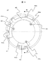
図2は一例として車両用交流発電機100の整流装置部分25の概略図である。整流装置25はU字形状をした樹脂材にて形成されており、4つのエリアに分割されている。4つのエリア中3つのエリア30a,30b,30cは整流部であり、今回三相の車両用交流発電機100を想定していることによる。整流部にはそれぞれのエリア毎に所望の整流素子と基板が配置されており、樹脂材内には導電性のある金属体をインサート成形しており、整流素子と基板の配置後、整流素子との電気的接続を行う。整流素子と基板の電気的接続が終わった後、このエリア30a,30b,30cに絶縁性のある樹脂材を流し込み、整流素子と基板並びに接合部の保護を行う。今回30a,30b,30c内に用いている整流素子はMOSFET(相補型金属酸化膜半導体)を想定している。4つのエリア中1つのエリア30dには、車両用交流発電機100の界磁巻線7に所望の電流を流す界磁駆動回路や、固定子コイル3から発生する出力電力を整流素子として使用するMOS−FETの駆動や、エリア30d近辺に設けられたコネクタ31を通して、CANやLINといった車両側との通信を行うICが組み込まれている。
FIG. 2 is a schematic diagram of the rectifying
また3つのエリア30a,30b,30cの一画には、それぞれ導電性のある金属体を整流装置25内にインサート成形した端子部32a,32b,32cがむき出しになっており、固定子コイル3と整流装置部分25間との電気的接続を行う。また整流装置部分25には車両側バッテリーとの直流電力入出力部である端子部33が設けられている。この端子部は外部から圧着端子付き電線が接続可能なようなボルト形状をしている。また先にも示したが図2に示す整流装置部分25の片面には円盤状のアルミニウムベース25Aが取り付けられており、回転子5に設けられたファン15の吸気効果により、アルミニウムベース25Aを冷却することで、整流装置25A上に配置してある整流素子や界磁駆動回路部分やIC類を冷却することが可能である。図2において整流装置25上にU字成形された樹脂部の欠損部分には、ブラシホルダー12とブラシ13を配置している。ブラシホルダー12は、アルミニウムベース25A上にボルト34等で固定され、更にブラシホルダー12は電気接続用の端子12a,12bを設け、30d内に設けた界磁駆動回路部との電気的接続を行う。
Further, in each of the three
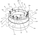
図3に固定子とコイル3と結線部品27が接続された状態を示す。また図4には結線部品27を図3のA方向から見た図を示し、図5には結線部品27をB−B断面にてカットした断面を示す。図3に示す例では固定子コイル3が三相のスター結線であり、出力線である口出し線3a,3b,3cと、中性線である口出し線3d,3e,3fの計6ヶ所の口出し線が突出している。一方、結線部品27は出力線結線用に三相分の導体、40,41,42と、中性線結線用の導体43を持ち、それぞれの導体には三相の出力線結線用にU字状の端子40a,41a,42aと、中性線結線用にU字状の端子43a,43b,43cの端子部を持ち、それぞれの口出し線3aから3fと電気的接続が行えるようになっている。結線部品27は図5の断面図に示すように、結線部品27の周囲を絶縁性のある樹脂29にて形成されており、樹脂29内部には電気的接続を行う導体40,41,42そして43がインサートされている。出力線結線用の導体40,41,42には整流装置25と接続するために、結線部40b,41b,42bが設けられており、図2で示した端子部32a,32b,32cとボルト28にて接続される。
FIG. 3 shows a state in which the stator, the
図4において出力線結線用の三相分の導体、40,41,42は、樹脂部分29で隠れている部分は点線で示しており、また中性線結線用の導体43は樹脂部品29から出た部分のみを記している。出力線結線を行う導体40,41,42は同一平面上に配置されており、導体40,41,42は中性線結線用導体43とは、樹脂部品29を介在させて配置している。今回の例では固定子コイル3がスター結線であるため、導体43が必要であるが、三相のデルタ結線である場合には、導体43は省略することが可能である。
In FIG. 4, three-
この例では端子と口出し線は端子を加締めた後、ハンダ接続を行うことで電気接続を行う形状となっているが、抵抗溶接等の接合技術を用いても良い。 In this example, the terminal and the lead wire are shaped to be electrically connected by soldering after crimping the terminal, but a joining technique such as resistance welding may be used.
また結線部品27の中央部には、固定用ボルト44がインサート成形されている。これは結線部品27をRブラケット11に固定するために設けられており、このボルト44がRブラケット11に設けられた貫通穴を通過した後、ナットにて固定される。今回このボルトは結線部品27を固定するためのものであり、振動条件等によってはリベット等で代用することも可能であり、更に振動条件が低い場合では、省略することも考えられる。図5に示すように、結線部品27の形状を担う樹脂部分29は、結線部品27の外周部分に傾斜部29Aが設けられている。この傾斜部29Aは固定子コイル3と結線されたとき図1の車両用交流発電機100において、整流装置5とは離れる方向に傾斜する形状となっている。
In addition, a fixing
回転子5の回転数が低い場合、ファン15によって取り込まれる冷却風50の風量は比較的少なく、結線部品27が介在しない状態では、固定子コイル3からの銅損熱が熱伝導性のよいアルミニウム製のRブラケット11に伝わり、Rブラケット11と整流装置25間の形成される冷却風の通風路、更には整流装置25のアルミベース25Aと伝わることとなり、固定子コイル3の熱が整流装置5の温度を上げてしまう。特に車両用交流発電機100の構造では、固定子コイル3と整流装置25間の距離が比較的短いため、上記温度上昇への影響は顕著である。
When the rotational speed of the rotor 5 is low, the air volume of the cooling
また今回、整流装置25内の整流素子はMOS−FETを想定している。現在、車両交流発電機に使用する整流素子は、ダイオードが主流であるが、MOS−FETにすることで、素子自体の抵抗を低く抑えることができ、車両交流発電機の効率向上へと繋がる。またMOS−FETはON−OFF制御が可能であるため、直流電源であるバッテリーから電力を供給し交流変換することで、回転電機を力行動作させることが可能となり、発電電動装置としても使用することが可能となる。
In addition, this time, it is assumed that the rectifying element in the rectifying
一方、MOS−FET自体の耐熱温度がダイオードに比べて低いことがあげられる。よってダイオードでは多少固定子コイル3から熱影響を受けても耐熱性が高いことから素子自体の耐力があったものの、整流素子をMOS−FETにすることで、固定子コイル3からの熱影響を抑制することが必須となる。
On the other hand, the heat-resistant temperature of the MOS-FET itself is lower than that of the diode. Therefore, although the diode has a high heat resistance even if it is somewhat affected by the heat from the
今回の実施形態では図2に示すとおり固定子コイル3と結線部品27を接続することで、図1に示すよう、比較的熱抵抗の高い樹脂部材で形成される結線部品27はRブラケット11と固定子コイル3間に配置されるようになる。よって結線部品27が固定子コイル3と整流装置間の断熱の役目をし、固定子コイル3からの発熱がRブラケット11に伝わるのを抑制することができ、整流装置5の温度上昇を抑えることが可能となる。
In this embodiment, by connecting the
また回転子5の回転数が高い場合、ファン15によって取り込まれる冷却風50の風量は比較的大きくなる。その際、結線部品27の樹脂傾斜部29Aが無い状態では、整流装置25のアルミベース25A及び固定子3を冷却した風50が、再度Rブラケット11と整流装置5間に流入してしまうこととなり、整流装置5を効率的に冷却するのが困難となる。今回の実施形態のように結線部分27に樹脂傾斜部29Aを設けることで、冷却風50が車両交流発電機100から排気される際、整流装置5とは離れる方向に排気されることとなるため、排気された冷却風50が再びRブラケット11と整流装置25間に流入することを抑制することができ、Rブラケット11と整流装置25間に外気と同等温度の冷却風を取り込むことが可能となる。今回の例では冷却風が車両用交流発電機100の外周側からのみRブラケット11と整流装置25の間に取り込まれるようにした。対し、Rブラッケト上の投影面積に対し、配置される部品が少なかったり、搭載部品を軸方向に重ねて配置したりすることで、車両用交流発電機100の軸方向からも冷却風を取り入れる構造にした場合、軸方向にも冷却フィンを形成できるよう整流装置25のアルミベース25Aを鋳物等で形成し、車両交流発電機100の外周側、軸方向から冷却風50を取り入れる構造にした場合でも、同じ効果が得られる。
When the rotation speed of the rotor 5 is high, the air volume of the cooling
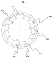
図6には図4の結線部品27に対し、結線部品27の固定子コイル3と向き合う面から見た図を示す。図6では図5まで記載の内容に存在しない板状部材27aが配置されている。図6では内径側から外径側に向けて板状部材が伸びるように配置されており、Rブラケット11の排気窓に合わせて上記板状部材27が設けられることで、よりスムーズな冷却風50の排気を促すこととなる。
FIG. 6 shows a view of the
図7には、本発明の一実施形態による車両用発電電動装置200の全体構成を示す断面を示す。図7の車両用発電電動装置の基本構成は、図1に示す車両用交流発電機100と同じように、ルンデル型回転子を備えた界磁巻線型回転機である。車両用発電電動装置200は、固定子201と回転子205を備え、固定子101は、固定子コア(固定子鉄心)202と、固定子コイル(電機子巻線)203を備えている。固定子201は回転子20を囲うように円筒状に形成され、固定子コア202は、円筒部とこの円筒部の内周側に、円筒部の中心に向かって突出した磁極部とからなる。固定子コア202は、円筒部に相当するリング部と、磁極部に相当する突出部がプレス打ち抜き成形された、薄い鋼板を重ねるように積上げられ、固定子コア202の外周を数箇所積層方向に溶接して形成されている。このスロット部に図には示さない絶縁紙204が挿入され、さらに固定子コイル203が挿入されることで、固定子コイル203が磁極部に巻回されている。上記固定子201はアルミニウム製のFブラケット210とRブラケット211間に位置し、通しボルトによって挟む形で固定されている。
In FIG. 7, the cross section which shows the whole structure of the
回転子205は、界磁巻線型回転機のルンデル型回転子である。回転子205は、回転子磁極206と、界磁巻線207を備えている。回転子磁極206は、2対のクロウポール型の磁極である。爪形磁極206Aと爪磁極206Bの爪部が互い違いに対向して回転子磁極206を構成し、その内周側に巻線枠208に界磁巻線207が巻回されて、回転子磁極206に収納されている。回転子磁極206がシャフト209に固定されることで、界磁巻線型回転機のルンデル型回転子205を構成する。界磁巻線207には、ブラシホルダー212に収納されたブラシ213から、スリップリング214を介して電流を供給され、クロウポール型の回転磁極206に磁束を発生させる。スリップリング214からは絶縁被覆を被った2本の電線が出ており、また同様にして界磁巻線207からも絶縁被覆を被った2本の電線を引き出し、界磁ターミナル部217にて接続固定されている。界磁ターミナル部217は界磁線を固定するよう加工がなされた金属板を絶縁性のある樹脂材にて一体成形したものであり、シャフト209に固定されている。
The
回転軸であるシャフト209はプーリー側軸受け218,反プーリー側軸受け219によって支持されている。
A
車両用発電電動装置200が車両のエンジンに取り付けられたとき、エンジン軸と回転子205のプーリー221はベルト等の連結部材を介して機械エネルギーの授受を行う。プーリー221はプーリーナット222にてシャフト209に取り付けられている。
When the vehicular generator-
プーリー側軸受け218の内輪側は、固定子コア202との位置調整を行うスペーサ220を介在させてシャフト209に取り付けられる。またプーリー側軸受け218の外輪側はFブラケット210の中心部に形成された筒状部分に納められ、おさえ板223とおさえ板用ボルト224にて固定されている。反プーリー側軸受け219の内輪側はシャフト209に圧入されており、また外輪側はRブラケット211の中心部に形成された筒状部分に収納される。また回転子磁極206には、車両用発電電動装置200の冷却のためにファン215,216が取り付けられており、回転子205の回転とともに、外気を車両用発電電動装置200内に取り込むことが可能となる。
The inner ring side of the pulley-
またRブラケット211には整流装置225がボルト226にて取り付けられており、また固定子コイル203には、結線部品227が取り付けられている。結線部品227と整流装置225はボルト228にて電気的に接続されている。整流装置225にはアルミベース225Aが取り付けられており、車両用発電電動装置200の外周側からRブラケット211と整流装置205の間をファン215によって取り込まれた冷却風250により冷却される。冷却風250はRブラケット211と整流装置225間から取り込まれ、Rブラケット211の中心近傍に設けられた通気孔を通り、固定子コイル203周囲を通過した後、Rブラケット周囲に設けられた排気孔を抜けて車両用発電電動装置200の外へと排気される。
Further, a
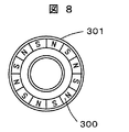
また今回図7に示す車両用発電電動装置200は磁極位置検出用の被検出体である磁気部材300と磁気部材ホルダー301を搭載している。更には磁極位置検出装置用の磁気検出手段302も同時に搭載している。図8には回転子の磁極位置検出装置用の被検出体である磁気部材300と磁気部材ホルダー301を示す。今回磁気部材は永久磁石とし、磁気部材ホルダー301はしぼり加工を施した鋼板で形成されている。磁気部材300である永久磁石は、今回固定子2の磁極が36個で、回転子コア206が12極であることから、周方向に12分割されて交互に着磁されている。また永久磁石の着磁方向は回転軸と同方向としている。磁気部材300は磁気部材ホルダー301内に、接着剤等で固定され、磁気部材ホルダー301がシャフト209に圧入されている。
In addition, the vehicular generator-
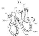
図9に磁極位置検出装置の磁気検出手段302の鳥瞰図を示している。今回の例では磁極位置検出装置の磁気検出手段302の磁気検出部材303は3個のホールICを用いている。3個のホールIC303は、同一円上でかつ等ピッチにて、磁気検出部材用基板304に配置されている。磁気検出部材用基板304は樹脂材を成形したセンサハウジングA305と、センサハウジングB306に収納され、センサハウジングB306に設けられた間口から信号線307を取り出して車両用発電電動装置200上の整流装置部分225に電気的に接続される。信号線307は、磁気検出部材303からの3個の出力信号と電源の+と−の計5個の信号線で構成されている。磁極位置検出装置の磁気検出手段302のセンサハウジングA305とセンサハウジングB306は接着剤等で固定され、センサハウジングA305に設けられたアーム部308によって、Rブラケット211にボルト等で固定される。また磁極309は磁気部材300からの磁束が磁気検出部材303により多く通過するよう、炭素鋼などの磁性体によって形成され、センサハウジングB306に取り付けられている。
FIG. 9 shows a bird's-eye view of the magnetic detection means 302 of the magnetic pole position detection device. In this example, the
アイドルストップ機能を備えた車両で本車両用発電電動装置が搭載された車両において、車両がアイドルストップから復帰する際、車両側からのアイドルストップ解除の信号や磁極位置検出装置の磁気検出手段302の信号などから、整流装置225部分に搭載されたMOS駆動用のICは、整流装置内のMOS−FETをON−OFFし、更には界磁駆動回路が界磁巻線207に所望の電流を流すことで、発電電動装置200を力行駆動させ、車両エンジンをスタートさせる。エンジン完爆後には、車両発電電動装置200は発電装置として働くこととなる。今回、磁気検出部材303はホールICを使用したが、磁気抵抗センサや、レゾルバなどを用いても良い。
In a vehicle having an idle stop function and equipped with this vehicle generator-motor apparatus, when the vehicle returns from the idle stop, the idle stop release signal from the vehicle side or the magnetic detection means 302 of the magnetic pole position detection device From the signal or the like, the MOS driving IC mounted in the
車両交流発電機100と同様、図7に示す結線部品227の外周側には、整流装置225とは離れる方向に傾斜部が設けられた形状となっている。
Similar to the
この効果は車両交流発電機100と同様、回転子205の回転数が低い場合、冷却風250の風量は比較的、結線部品227が介在しない状態では、固定子コイル203からの熱が整流装置225の温度上昇を促してしまう。
This effect is the same as in the
今回の実施形態では図2に示すとおり固定子コイル3と結線部品27を接続することで、結線部品227が固定子コイル203と整流装置225間の断熱の役目をし、固定子コイル203が整流装置225の温度上昇を促すのを抑制することができる。
In this embodiment, by connecting the
特に本実施例の発電電動装置では、停止状態のエンジンを回転させる力行動作を要するため、固定子コイルには回転数の低い状態で大きな電流を通電する必要があり、固定子コイルからの発熱量はより大きなものとなる。よって結線部品227は固定子コイル203と整流装置間225の断熱に大きく寄与するものとなる。
In particular, the generator-motor apparatus of the present embodiment requires a power running operation to rotate the engine in a stopped state, so that a large current needs to be supplied to the stator coil at a low rotational speed, and the amount of heat generated from the stator coil. Will be bigger. Therefore, the connection component 227 greatly contributes to the heat insulation between the
また回転子205の回転数が高い場合、ファン215によって取り込まれる冷却風250の風量は比較的大きくなる。その際、結線部分227に樹脂傾斜部を設けることで、冷却風250が車両用発電電動装置200から排気される際、整流装置225とは離れる方向に排気されることとなるため、排気された冷却風250が再びRブラケット211と整流装置225間に流入することを抑制することができ、Rブラケット211と整流装置225間に外気と同等温度の冷却風を取り込むことが可能となる。
When the rotation speed of the
今回の車両用発電電装装置200では、冷却風250が車両用発電電装装置200の外周側からのみ取り込まれるようにしたが、車両用交流発電機100に示した同様の事情で、軸方向からも冷却風を取り入れることが可能な場合には軸方向側にも整流装置225のアルミベース225Aを延長し、整流装置225を外周方向,軸方向から冷却できる構造にした場合でも、同じ効果が得られる。
In the vehicle generator /
また図6のように結線部品227の固定子コイル203と向き合う面に、内径側から外径側に向けて板状部材が伸びるように配置しても、車両交流発電機100と同様の効果が得られる。
Moreover, even if it arrange | positions so that a plate-shaped member may extend toward the outer-diameter side from the inner diameter side in the surface facing the
以上説明したように、本実施形態によれば、整流素子と固定子コイルを接続する部材の代わりに、車両用交流発電機において、固定子コイルと整流装置間を電気的に接続する導体と、その周囲を絶縁材部材で形成する結線部品を、固定子コイルと整流装置間に介在させることで、接続部品が断熱材の役目を果たし、新たな部品の追加無しに、固定子コイルからの発熱が整流装置の温度を上げることを抑制することができる。 As described above, according to the present embodiment, instead of the member that connects the rectifier element and the stator coil, in the vehicle AC generator, the conductor that electrically connects the stator coil and the rectifier, Connecting parts that form the periphery of the insulating material between the stator coil and the rectifier allow the connecting part to act as a heat insulator, and heat is generated from the stator coil without adding new parts. Can suppress the temperature of the rectifier from being raised.
また接続部品の固定子コイルと向き合う面の外周側に、整流装置とは離れる方向に傾斜部を設けることで、リアブラケットと整流装置間から流入した冷却風が、整流装置,固定子コイルを冷却した後、再度リアブラケットと整流装置間に流入することを抑制することができ、整流装置の効率的な冷却を行うことができる。 In addition, by providing an inclined part in the direction away from the rectifier on the outer peripheral side of the surface of the connecting part that faces the stator coil, the cooling air flowing from between the rear bracket and the rectifier cools the rectifier and stator coil. After that, it is possible to suppress the flow again between the rear bracket and the rectifier, and the rectifier can be efficiently cooled.
更には本実施形態では車両用発電電動装置が車両交流発電機に似たような構成である場合に同様に適用できるものである。 Furthermore, the present embodiment can be similarly applied when the vehicular generator-motor apparatus has a configuration similar to a vehicle AC generator.
特に整流素子としてMOS−FETを採用した場合には、MOS−FETの耐熱温度は、通常整流素子として使われているダイオードに比べて低いため、固定子コイルと整流装置間に断熱部材によって形成される接続部品を介在させることは、MOS−FETの温度上昇を抑えるのに有効なものである。 In particular, when a MOS-FET is used as the rectifying element, the heat-resistant temperature of the MOS-FET is lower than that of a diode normally used as a rectifying element, so it is formed by a heat insulating member between the stator coil and the rectifying device. It is effective to suppress the temperature rise of the MOS-FET.
1 固定子
3 固定子コイル
5 回転子
6 回転子磁極
9 シャフト
11 Rブラケット
15 ファン(リア側)
25 整流装置
27 結線部品
1
25
Claims (8)
前記回転子に取り付けられ回転子の回転により冷却風を発生させるファンと、
固定子巻線を有し、前記回転子の外周に配置された固定子と、
前記軸受け及び前記固定子を支持するとともに、前記ファンによって発生した冷却風の通路を形成するブラケットと、
前記回転子から発生した電力を整流する整流装置と、
前記固定子巻線と前記整流装置間を電気的に接続する導電体と、
前記導電体の周囲を絶縁部材で形成する結線部品と、を有し、
前記固定子の固定子巻線と整流装置間に前記結線部品を配置した車両用交流発電機。 A rotor having a rotor magnetic pole, and a rotating shaft to which the rotor magnetic pole is fixed is rotatably supported by two or more bearings;
A fan attached to the rotor for generating cooling air by rotation of the rotor;
A stator having a stator winding and disposed on the outer periphery of the rotor;
A bracket that supports the bearing and the stator and forms a passage for cooling air generated by the fan;
A rectifier for rectifying the electric power generated from the rotor;
A conductor for electrically connecting the stator winding and the rectifier;
A wiring component that forms the periphery of the conductor with an insulating member;
An automotive alternator in which the wiring components are arranged between a stator winding of the stator and a rectifier.
前記結線部品を構成する絶縁部材における前記固定子側と向かい合う面の外径側部分に、整流装置とは離れる方向に傾斜が施されている車両用交流発電機。 The vehicle alternator according to claim 1,
The AC generator for vehicles by which the outer diameter side part of the surface facing the said stator side in the insulating member which comprises the said connection component is inclined in the direction away from a rectifier.
前記固定子側と向かい合う面には絶縁部材で形成される複数の突出した板状部材が、略内径側から外径側へ伸びるように配置されている車両用交流発電機。 The vehicle alternator according to claim 2,
An AC generator for a vehicle in which a plurality of protruding plate-like members formed of insulating members are arranged on a surface facing the stator side so as to extend from a substantially inner diameter side to an outer diameter side.
前記整流装置に組み込まれている整流素子が、MOSFETである車両用交流発電機。 The vehicle alternator according to claim 1,
An automotive alternator in which a rectifying element incorporated in the rectifier is a MOSFET.
前記回転子に取り付けられ回転子の回転により冷却風を発生させるファンと、
固定子巻線を有し、前記回転子の外周に配置された固定子と、
前記軸受け及び前記固定子を支持するとともに、前記ファンによって発生した冷却風の通路を形成するブラケットと、
前記回転子から発生した電力を整流する整流装置と、
前記固定子巻線と前記整流装置間を電気的に接続する導電体と、
前記導電体の周囲を絶縁部材で形成する結線部品と、
前記回転子の回転位置を検出する磁気検出手段と、を有し、
前記固定子の固定子巻線と整流装置間に前記結線部品を配置した車両用発電電動装置。 A rotor having a rotor magnetic pole, and a rotating shaft to which the rotor magnetic pole is fixed is rotatably supported by two or more bearings;
A fan attached to the rotor for generating cooling air by rotation of the rotor;
A stator having a stator winding and disposed on the outer periphery of the rotor;
A bracket that supports the bearing and the stator and forms a passage for cooling air generated by the fan;
A rectifier for rectifying the electric power generated from the rotor;
A conductor for electrically connecting the stator winding and the rectifier;
Wire connection parts that form the periphery of the conductor with an insulating member;
Magnetic detection means for detecting the rotational position of the rotor,
A vehicular generator-motor apparatus in which the connection parts are arranged between a stator winding of the stator and a rectifier.
前記結線部品を構成する絶縁部材における前記固定子側と向かい合う面の外径側部分に、整流装置とは離れる方向に傾斜が施されている車両用発電電動装置。 The vehicular generator-motor apparatus according to claim 5,
A vehicular generator-motor apparatus in which an outer diameter side portion of a surface facing the stator side of an insulating member constituting the wiring component is inclined in a direction away from the rectifier.
前記固定子側と向かい合う面には絶縁部材で形成される複数の突出した板状部材が、略内径側から外径側へ伸びるよう配置されている車両用発電電動装置。 The vehicular generator-motor apparatus according to claim 6,
A vehicular generator-motor apparatus in which a plurality of protruding plate-like members formed of an insulating member are arranged on a surface facing the stator side so as to extend from a substantially inner diameter side to an outer diameter side.
前記整流装置に組み込まれている整流素子が、MOSFETである車両用発電電動装置。 The vehicle alternator according to claim 5,
A vehicular generator-motor apparatus in which a rectifier element incorporated in the rectifier is a MOSFET.
Priority Applications (1)
| Application Number | Priority Date | Filing Date | Title |
|---|---|---|---|
| JP2009083984A JP2010239727A (en) | 2009-03-31 | 2009-03-31 | Ac generator for vehicle and generator motor device for vehicle |
Applications Claiming Priority (1)
| Application Number | Priority Date | Filing Date | Title |
|---|---|---|---|
| JP2009083984A JP2010239727A (en) | 2009-03-31 | 2009-03-31 | Ac generator for vehicle and generator motor device for vehicle |
Publications (1)
| Publication Number | Publication Date |
|---|---|
| JP2010239727A true JP2010239727A (en) | 2010-10-21 |
Family
ID=43093576
Family Applications (1)
| Application Number | Title | Priority Date | Filing Date |
|---|---|---|---|
| JP2009083984A Pending JP2010239727A (en) | 2009-03-31 | 2009-03-31 | Ac generator for vehicle and generator motor device for vehicle |
Country Status (1)
| Country | Link |
|---|---|
| JP (1) | JP2010239727A (en) |
Cited By (4)
| Publication number | Priority date | Publication date | Assignee | Title |
|---|---|---|---|---|
| JP2013255296A (en) * | 2012-06-05 | 2013-12-19 | Mitsubishi Electric Corp | Control unit built-in rotary electric machine |
| CN103797690A (en) * | 2011-08-08 | 2014-05-14 | 三菱电机株式会社 | Control-device-integrated rotating electrical machine and method for assembling and disassembling the same |
| JP2014107916A (en) * | 2012-11-27 | 2014-06-09 | Mitsubishi Electric Corp | Rotary electric machine |
| JP2021164347A (en) * | 2020-04-02 | 2021-10-11 | 三菱電機株式会社 | Control apparatus built-in rotary electric machine |
Citations (3)
| Publication number | Priority date | Publication date | Assignee | Title |
|---|---|---|---|---|
| JPH0919119A (en) * | 1995-06-28 | 1997-01-17 | Mitsubishi Electric Corp | Vehicle alternator |
| JPH09172752A (en) * | 1995-12-19 | 1997-06-30 | Denso Corp | Ac generator |
| JP2001037131A (en) * | 1999-07-15 | 2001-02-09 | Mitsubishi Electric Corp | AC generator for vehicles |
-
2009
- 2009-03-31 JP JP2009083984A patent/JP2010239727A/en active Pending
Patent Citations (3)
| Publication number | Priority date | Publication date | Assignee | Title |
|---|---|---|---|---|
| JPH0919119A (en) * | 1995-06-28 | 1997-01-17 | Mitsubishi Electric Corp | Vehicle alternator |
| JPH09172752A (en) * | 1995-12-19 | 1997-06-30 | Denso Corp | Ac generator |
| JP2001037131A (en) * | 1999-07-15 | 2001-02-09 | Mitsubishi Electric Corp | AC generator for vehicles |
Cited By (7)
| Publication number | Priority date | Publication date | Assignee | Title |
|---|---|---|---|---|
| CN103797690A (en) * | 2011-08-08 | 2014-05-14 | 三菱电机株式会社 | Control-device-integrated rotating electrical machine and method for assembling and disassembling the same |
| JP5657120B2 (en) * | 2011-08-08 | 2015-01-21 | 三菱電機株式会社 | Control device-integrated rotating electrical machine and assembly / disassembly method thereof |
| CN103797690B (en) * | 2011-08-08 | 2017-03-29 | 三菱电机株式会社 | Control-device-integrated rotating electrical machine and method for assembling and disassembling the same |
| JP2013255296A (en) * | 2012-06-05 | 2013-12-19 | Mitsubishi Electric Corp | Control unit built-in rotary electric machine |
| US8970076B2 (en) | 2012-06-05 | 2015-03-03 | Mitsubishi Electric Corporation | Controller-integrated rotating electrical machine |
| JP2014107916A (en) * | 2012-11-27 | 2014-06-09 | Mitsubishi Electric Corp | Rotary electric machine |
| JP2021164347A (en) * | 2020-04-02 | 2021-10-11 | 三菱電機株式会社 | Control apparatus built-in rotary electric machine |
Similar Documents
| Publication | Publication Date | Title |
|---|---|---|
| US8253287B2 (en) | Automotive dynamoelectric machine | |
| CN107534369B (en) | AC generator for vehicle | |
| CN104137397B (en) | Electric rotating machine | |
| JP2006166681A (en) | Motor control device | |
| JP2016059133A (en) | Rotating electric machine | |
| CN101924422B (en) | Automotive alternator and method for manufacturing a rectifying apparatus mounted thereto | |
| JP4575385B2 (en) | AC generator rectifier | |
| JP4620117B2 (en) | AC generator | |
| JP4549924B2 (en) | Rotating electric machine for vehicles | |
| CN100511927C (en) | Vehicle dynamo-electric machine apparatus | |
| JP6324531B2 (en) | AC generator for vehicles | |
| JP2010239727A (en) | Ac generator for vehicle and generator motor device for vehicle | |
| WO2016079866A1 (en) | Ac generator for vehicles | |
| JP2008187853A (en) | Rotating electrical machine equipment | |
| CN101938193B (en) | Rotary motor | |
| JP4450134B2 (en) | Brushless alternator | |
| JP5701346B2 (en) | Rotating electric machine | |
| JP2010098856A (en) | Motor generator | |
| JPWO2016079867A1 (en) | AC generator for vehicles | |
| JP6995163B2 (en) | Generator motor | |
| CN104852504B (en) | car alternator | |
| JP2002142424A (en) | AC generator for vehicles | |
| JP2018121458A (en) | Controller built-in dynamoelectric machine | |
| JP2012235553A (en) | Vehicle ac generator | |
| JP2010041850A (en) | Rotary electric machine |
Legal Events
| Date | Code | Title | Description |
|---|---|---|---|
| A621 | Written request for application examination |
Free format text: JAPANESE INTERMEDIATE CODE: A621 Effective date: 20100917 |
|
| A521 | Written amendment |
Free format text: JAPANESE INTERMEDIATE CODE: A523 Effective date: 20100917 |
|
| A977 | Report on retrieval |
Free format text: JAPANESE INTERMEDIATE CODE: A971007 Effective date: 20120907 |
|
| A131 | Notification of reasons for refusal |
Free format text: JAPANESE INTERMEDIATE CODE: A131 Effective date: 20121002 |
|
| A521 | Written amendment |
Free format text: JAPANESE INTERMEDIATE CODE: A523 Effective date: 20121203 |
|
| A131 | Notification of reasons for refusal |
Free format text: JAPANESE INTERMEDIATE CODE: A131 Effective date: 20130521 |
|
| A02 | Decision of refusal |
Free format text: JAPANESE INTERMEDIATE CODE: A02 Effective date: 20131001 |