JP2010242532A - Variable valve operating device for internal combustion engine - Google Patents
Variable valve operating device for internal combustion engine Download PDFInfo
- Publication number
- JP2010242532A JP2010242532A JP2009089593A JP2009089593A JP2010242532A JP 2010242532 A JP2010242532 A JP 2010242532A JP 2009089593 A JP2009089593 A JP 2009089593A JP 2009089593 A JP2009089593 A JP 2009089593A JP 2010242532 A JP2010242532 A JP 2010242532A
- Authority
- JP
- Japan
- Prior art keywords
- variable valve
- phase
- restricting
- restriction
- internal combustion
- Prior art date
- Legal status (The legal status is an assumption and is not a legal conclusion. Google has not performed a legal analysis and makes no representation as to the accuracy of the status listed.)
- Pending
Links
Images



Landscapes
- Valve Device For Special Equipments (AREA)
- Output Control And Ontrol Of Special Type Engine (AREA)
Abstract
【課題】バルブスタンプを抑制する機能及びバルブタイミングを固定する機能を備えるとともに、これら機能を実現するための構造の複雑化を抑制することのできる内燃機関の可変動弁装置を提供する。
【解決手段】この可変動弁装置は、ハウジングロータ31とベーンロータ35との相対回転の位相を操作してバルブタイミングを変更するバルブタイミング可変機構30と、前記相対回転の範囲を制限する規制機構4とを備える。規制機構4は、ベーンロータ35に収容される収容位置と同ロータ35から突出した第1及び第2突出位置との間で移動する規制ピン60と、ハウジングロータ31に設けられて第1及び第2突出位置にある規制ピン60がそれぞれはめ込まれるロック穴41及び規制溝51とから構成される。そして、規制ピン60がロック穴41にはめ込まれるときに前記相対回転位相が固定され、規制溝51にはめ込まれるときに前記相対回転範囲が制限される。
【選択図】図2Provided is a variable valve operating apparatus for an internal combustion engine that has a function of suppressing a valve stamp and a function of fixing a valve timing, and that can suppress the complexity of a structure for realizing these functions.
This variable valve operating apparatus operates a relative rotation phase between a housing rotor and a vane rotor to change a valve timing, and a restriction mechanism restricts the relative rotation range. With. The restriction mechanism 4 is provided on the housing rotor 31 between the accommodation position accommodated in the vane rotor 35 and the first and second projecting positions projecting from the rotor 35, and the first and second. It is composed of a lock hole 41 and a regulation groove 51 into which the regulation pin 60 at the protruding position is fitted. The relative rotation phase is fixed when the restriction pin 60 is fitted in the lock hole 41, and the relative rotation range is restricted when the restriction pin 60 is fitted in the restriction groove 51.
[Selection] Figure 2
Description
本発明は、クランクシャフトに連動する入力回転体と機関弁としての吸気弁または排気弁のカムシャフトに連動する出力回転体との相対的な回転位相を最遅角位相と最進角位相との間で操作して、同機関弁のバルブタイミングを最進角と最遅角との間で変更するバルブタイミング可変機構と、入力回転体と出力回転体との相対回転の範囲を最遅角位相から最進角位相までの範囲よりも制限する規制機構とを備える内燃機関の可変動弁装置に関する。 The present invention relates to the relative rotation phase between the input rotator linked to the crankshaft and the output rotator linked to the camshaft of the intake valve or exhaust valve as the engine valve between the most retarded angle phase and the most advanced angle phase. The valve timing variable mechanism that changes the valve timing of the engine valve between the most advanced angle and the most retarded angle, and the range of relative rotation between the input rotator and output rotator is the most retarded phase. The present invention relates to a variable valve operating apparatus for an internal combustion engine that includes a restriction mechanism that restricts the range from the range to the most advanced phase.
車載エンジン等の内燃機関において、最適な条件で燃料を燃焼させるために、吸気バルブの最大バルブリフト量を可変とするバルブリフト量可変機構と、吸気バルブのバルブタイミングを可変とするバルブタイミング可変機構とを有した可変動弁装置が提案されている。 In an internal combustion engine such as an in-vehicle engine, a variable valve lift mechanism that varies the maximum valve lift amount of the intake valve and a variable valve timing mechanism that varies the valve timing of the intake valve in order to burn fuel under optimum conditions. There has been proposed a variable valve operating apparatus having the following.
このような可変動弁装置は、バルブリフト量可変機構により吸気バルブの最大バルブリフト量を大きくした場合、バルブタイミングの進角に起因して吸気バルブとピストンとが干渉するいわゆるバルブスタンプが生じることもある。 In such a variable valve system, when the maximum valve lift amount of the intake valve is increased by a variable valve lift amount mechanism, a so-called valve stamp in which the intake valve and the piston interfere due to the advance angle of the valve timing occurs. There is also.
そこで、特許文献1においては、このようなバルブスタンプを回避するためにバルブタイミング可変機構の駆動範囲を規制する規制機構が提案されている。当該技術では、吸気バルブのカムを最大バルブリフト量が小さい低速カムから最大バルブリフト量が大きい高速カムに切替えたときに、ベーンロータ(出力回転体)の規制ピン(規制体)をスプロケット(入力回転体)に設けられた規制溝に挿入することにより、ベーンロータが進角規制位相を超えて進角することを規制している。これにより、吸気バルブの最大バルブリフト量を大きく設定したときに、バルブタイミングがバルブスタンプをまねくところにまで進角することは回避されるようになる。 Therefore, Patent Document 1 proposes a regulation mechanism that regulates the drive range of the variable valve timing mechanism in order to avoid such a valve stamp. In this technology, when the intake valve cam is switched from a low-speed cam with a small maximum valve lift amount to a high-speed cam with a large maximum valve lift amount, the restriction pin (regulator member) of the vane rotor (output rotor) is sprocketed (input rotation). The vane rotor is prevented from being advanced beyond the advance angle restriction phase by being inserted into a restriction groove provided in the body). As a result, when the maximum valve lift amount of the intake valve is set to be large, it is avoided that the valve timing is advanced to the point where the valve stamp is caused.
一方、ベーンロータから突出したピンをスプロケットの穴にはめ込みスプロケットに対するベーンロータの回転位相を固定することにより、機関始動時のバルブタイミングを所定のタイミングに固定するためのロック機構を有するバルブタイミング可変機構も知られている(例えば、特許文献2)。 On the other hand, a variable valve timing mechanism having a lock mechanism for fixing the valve timing at the start of the engine to a predetermined timing by inserting a pin protruding from the vane rotor into the hole of the sprocket and fixing the rotational phase of the vane rotor with respect to the sprocket is also known. (For example, Patent Document 2).
そして、ベーンロータの回転範囲を制限する規制機構と、ベーンロータの回転位相を固定するロック機構とを併せて備えることにより、バルブスタンプの回避と機関始動性の確保とを実現することが可能となり、バルブタイミング可変機構としての実用性はより高められるようになる。 By providing a regulation mechanism that limits the rotation range of the vane rotor and a lock mechanism that fixes the rotation phase of the vane rotor, it is possible to avoid valve stamps and ensure engine startability. Practicality as a timing variable mechanism can be further enhanced.
しかし、上記規制機構及び上記ロック機構の両者を可変動弁装置に採用した場合、ベーンロータ及びスプロケットのそれぞれに規制機構のピン及び溝並びにロック機構のピン及び穴を形成する必要が生じるため、当該装置の構成の複雑化は避けられないものとなる。 However, when both the restriction mechanism and the lock mechanism are employed in the variable valve device, it is necessary to form the pin and groove of the restriction mechanism and the pin and hole of the lock mechanism in each of the vane rotor and the sprocket. The complexity of the configuration is inevitable.
本発明はこのような実情に鑑みてなされたものであり、その目的は、バルブスタンプを抑制する機能及びバルブタイミングを固定する機能を備えるとともに、これら機能を実現するための構造の複雑化を抑制することのできる内燃機関の可変動弁装置を提供することにある。 The present invention has been made in view of such circumstances, and its purpose is to provide a function of suppressing a valve stamp and a function of fixing a valve timing, and to suppress the complexity of the structure for realizing these functions. It is an object of the present invention to provide a variable valve operating apparatus for an internal combustion engine that can be used.
以下、上記目的を達成するための手段及びその作用効果について記載する。
(1)請求項1に記載の発明は、クランクシャフトに連動する入力回転体と機関弁としての吸気弁または排気弁のカムシャフトに連動する出力回転体との相対的な回転位相を最遅角位相と最進角位相との間で操作して同機関弁のバルブタイミングを最進角と最遅角との間で変更するバルブタイミング可変機構と、前記入力回転体と前記出力回転体との相対回転の範囲を最遅角位相から最進角位相までの範囲よりも制限する規制機構とを備える内燃機関の可変動弁装置において、前記規制機構は、前記出力回転体に収容される収容位置と前記出力回転体から突出した第1の突出位置及び第2の突出位置との間で移動する規制体と、前記入力回転体に設けられて前記第1の突出位置にある前記規制体がはめ込まれる規制穴と、前記入力回転体に設けられて前記第2の突出位置にある前記規制体がはめ込まれる規制溝とを含めて構成されるものであり、当該可変動弁装置は、前記規制体が前記規制穴にはめ込まれた状態にあるときに前記入力回転体と前記出力回転体との相対回転位相が固定され、前記規制体が前記規制溝にはめ込まれた状態にあるときに前記入力回転体と前記出力回転体との相対回転範囲が最遅角位相から最進角位相までの範囲よりも小さい範囲に制限されるものであることを要旨としている。
In the following, means for achieving the above object and its effects are described.
(1) According to the first aspect of the present invention, the relative rotational phase between the input rotating body interlocking with the crankshaft and the output rotating body interlocking with the camshaft of the intake valve or exhaust valve as the engine valve is the most retarded angle. A variable valve timing mechanism that operates between the phase and the most advanced angle phase to change the valve timing of the engine valve between the most advanced angle and the most retarded angle; and the input rotator and the output rotator. And a restriction mechanism that restricts a range of relative rotation from a range from the most retarded phase to the most advanced angle phase. And a regulating body that moves between a first projecting position and a second projecting position that project from the output rotating body, and the regulating body that is provided on the input rotating body and is in the first projecting position is fitted. Control holes and the input rotor And a restriction groove into which the restriction body at the second protruding position is fitted, and the variable valve operating apparatus is in a state in which the restriction body is fitted in the restriction hole. Sometimes the relative rotation phase between the input rotator and the output rotator is fixed when the relative rotation phase between the input rotator and the output rotator is fixed, and the restrictor is in the restricting groove. Is limited to a range smaller than the range from the most retarded phase to the most advanced phase.
この発明によれば、一つの規制体を第1及び第2の突出位置において規制穴及び規制溝とはめ込むことにより出力回転体の入力回転体に対する回転を禁止もしくは規制しているため、一つの規制体で出力回転体の入力回転体の相対回転位相の固定及び相対回転範囲の制限をすることができるようになる。従って、バルブスタンプを抑制する機能及びバルブタイミングを固定する機能を備えるとともに、これら機能を実現するための構造の複雑化を抑制することができるようになる。 According to the present invention, the rotation of the output rotating body relative to the input rotating body is prohibited or restricted by fitting one restricting body with the restricting hole and the restricting groove at the first and second projecting positions. It is possible to fix the relative rotational phase of the input rotating body of the output rotating body and limit the relative rotational range with the body. Accordingly, the function of suppressing the valve stamp and the function of fixing the valve timing are provided, and the complexity of the structure for realizing these functions can be suppressed.
(2)請求項2に記載の発明は、請求項1に記載の内燃機関の可変動弁装置において、前記規制体が前記規制溝にはめ込まれた状態にあるときに前記入力回転体と前記出力回転体との相対回転の範囲が前記最進角位相よりも遅角側にある進角規制位相から前記最遅角位相までの範囲に制限されることを要旨としている。
(2) The invention according to
この発明によれば、規制体が規制溝とはめ込まれた状態にあるとき、出力回転体は、入力回転体に対して進角規制位相を超えて進角側に回転することが規制される一方、出力回転体が遅角側に回転するときには遅角規制位相に至るまでその回転が許容される。 According to this invention, when the restricting body is fitted in the restricting groove, the output rotating body is restricted from rotating to the advance side beyond the advance angle restricting phase with respect to the input rotating body. When the output rotating body rotates to the retard side, the rotation is allowed until the retard angle regulation phase is reached.
(3)請求項3に記載の発明は、請求項1に記載の内燃機関の可変動弁装置において、前記規制体が前記規制溝にはめ込まれた状態にあるときに前記入力回転体と前記出力回転体との相対回転の範囲が前記最遅角位相よりも進角側にある遅角規制位相から前記最進角位相までの範囲に制限されることを要旨としている。 (3) According to a third aspect of the present invention, in the variable valve operating apparatus for an internal combustion engine according to the first aspect, the input rotating body and the output when the restricting body is fitted in the restricting groove. The gist is that the range of relative rotation with the rotating body is limited to a range from the retard restriction phase that is on the more advanced side than the most retarded phase to the most advanced phase.
この発明によれば、規制体が規制溝とはめ込まれた状態にあるとき、出力回転体は、入力回転体に対して遅角規制位相を超えて遅角側に回転することが規制される一方、出力回転体が進角側に回転するときには進角規制位相に至るまでその回転が許容される。 According to this invention, when the restricting body is fitted in the restricting groove, the output rotating body is restricted from rotating to the retard side beyond the retard angle regulating phase with respect to the input rotating body. When the output rotating body rotates to the advance side, the rotation is allowed until the advance angle regulation phase is reached.
(4)請求項4に記載の発明は、請求項1〜3のいずれか一項に記載の内燃機関の可変動弁装置において、前記規制体が前記規制穴にはめ込まれた状態にあるときに前記入力回転体に対する前記出力回転体の回転位相が前記最遅角位相に固定されることを要旨としている。 (4) The invention according to claim 4 is the variable valve operating apparatus for an internal combustion engine according to any one of claims 1 to 3, wherein the restricting body is fitted in the restricting hole. The gist is that the rotational phase of the output rotator relative to the input rotator is fixed at the most retarded phase.
この発明によれば、規制体が規制穴と係合した状態にあるとき、出力回転体は、最遅角位相にて入力回転体に対して固定される。
(5)請求項5に記載の発明は、請求項1〜4のいずれか一項に記載の内燃機関の可変動弁装置において、前記規制体は、前記出力回転体に対して同回転体の軸方向の一方に突出して前記収容位置から前記第1の突出位置に移動し、前記出力回転体に対して同回転体の軸方向の他方に突出して前記収容位置から前記第2の突出位置に移動することを要旨としている。
According to this invention, when the restricting body is engaged with the restricting hole, the output rotating body is fixed to the input rotating body at the most retarded phase.
(5) The invention according to claim 5 is the variable valve operating apparatus for an internal combustion engine according to any one of claims 1 to 4, wherein the restricting body is the same as the rotating body with respect to the output rotating body. Projecting in one axial direction to move from the accommodation position to the first projecting position, projecting from the output position to the other axial direction of the rotating body, and from the housing position to the second projecting position. The gist is to move.
(6)請求項6に記載の発明は、請求項1〜5のいずれか一項に記載の内燃機関の可変動弁装置において、当該可変動弁装置は、前記バルブタイミング可変機構及び前記規制機構のそれぞれに対する作動油の給排を通じてこれら機構を操作する油圧機構をさらに備えるものであり、前記規制機構は、前記油圧機構から供給される作動油により前記規制体を前記第2の突出位置に向けて押す作動室と、前記規制体を前記第1の突出位置に向けて押すばねとが設けられるとともに、これら作動室及びばねの力の関係により前記規制体を前記収容位置と前記第1の突出位置及び前記第2の突出位置の間で移動させるものであることを要旨としている。 (6) The invention according to claim 6 is the variable valve operating apparatus for an internal combustion engine according to any one of claims 1 to 5, wherein the variable valve operating apparatus includes the variable valve timing mechanism and the regulating mechanism. And a hydraulic mechanism that operates these mechanisms through supply and discharge of hydraulic oil to and from each of the hydraulic oils, and the regulating mechanism directs the regulating body to the second projecting position by hydraulic oil supplied from the hydraulic mechanism. And a spring that pushes the restricting body toward the first projecting position, and the restricting body is placed between the housing position and the first projecting due to the relationship between the working chamber and the spring force. The gist is to move between the position and the second protruding position.
この発明によれば、可変動弁装置の油圧機構を通じて作動室に供給される作動油及びばねがそれぞれ規制体に対して第2突出位置方向及び第1突出位置方向への力を付与するため、規制体の移動及び位置の保持を実現するために新たな油圧機構を設ける必要がない。 According to this invention, the hydraulic oil and the spring supplied to the working chamber through the hydraulic mechanism of the variable valve operating device respectively apply force in the second projecting position direction and the first projecting position direction to the regulating body. There is no need to provide a new hydraulic mechanism in order to realize the movement of the regulating body and the holding of the position.
(7)請求項7に記載の発明は、請求項6に記載の内燃機関の可変動弁装置において、前記出力回転体は、前記規制体を収容する収容室が設けられるものであり、前記規制体は、前記規制穴または前記規制溝にはめ込まれる規制本体と、この規制本体に設けられて前記収容室を前記ばねが設けられるばね室と前記作動室とに区画する規制区画体とを含めて構成されるものであり、前記ばね室は、前記規制体の移動方向において前記規制区画体に対して前記第2の突出位置側に設けられるものであり、前記作動室は、前記規制体の移動方向において前記規制区画体に対して前記第1の突出位置側に設けられるものであることを要旨としている。
(7) The invention according to
(8)請求項8に記載の発明は、請求項7に記載の内燃機関の可変動弁装置において、前記作動室の力が前記ばねの力を上回る条件のもと前記入力回転体に対する前記出力回転体の回転位相が前記規制体と前記規制溝との対応を維持する位相にあるとき、前記規制体が前記作動室の力により前記第2の突出位置に移動し、前記ばねの力が前記作動室の力を上回る条件のもと前記入力回転体に対する前記出力回転体の回転位相が前記規制体と前記規制穴との対応を維持する位相にあるとき、前記規制体が前記ばねの力により前記第1の突出位置に移動することを要旨としている。
(8) The invention according to claim 8 is the variable valve operating apparatus for the internal combustion engine according to
(9)請求項9に記載の発明は、請求項7または8に記載の内燃機関の可変動弁装置において、前記規制機構は、前記作動室の作動油を排出する排出路が設けられるものであり、前記規制体は、前記作動室の作動油が前記排出路により排出されるときに前記第1の突出位置に向かう力が前記第2の突出位置に向かう力を上回り、前記作動室に作動油が供給されるときに前記第1の突出位置に向かう力が前記第2の突出位置に向かう力を下回るものであることを要旨としている。
(9) The invention according to claim 9 is the variable valve operating apparatus for an internal combustion engine according to
(10)請求項10に記載の発明は、請求項7〜9のいずれか一項に記載の内燃機関の制御装置において、前記バルブタイミング可変機構は、前記出力回転体の軸方向において同回転体を介して互いに対向する第1部位及び第2部位のそれぞれに前記規制穴及び前記規制溝が設けられるものであり、前記規制体は、その一方の先端部と前記規制穴が設けられる前記第1部位との間にある空間と前記規制溝とを連通する連通孔が前記規制本体に設けられるものであることを要旨としている。
(10) The invention according to
規制体が第2の突出位置に突出し、規制溝にはめ込まれた状態において、作動油が給排される作動室以外の室と規制溝とが連通することがある。このとき、連通した室の作動油が規制溝内に流入すると、規制体に対してこの流入した作動油に基づく力が付与されてしまうことになる。すると、規制体がこの力に基づいて第1の突出位置側に移動してしまうおそれが生じる。 When the restricting body protrudes to the second protruding position and is fitted in the restricting groove, the restricting groove may communicate with a chamber other than the working chamber through which hydraulic oil is supplied and discharged. At this time, when the hydraulic fluid in the communicating chamber flows into the restriction groove, a force based on the flowed hydraulic oil is applied to the regulating body. Then, there exists a possibility that a control body may move to the 1st protrusion position side based on this force.
そこで本発明では、規制体に連通孔を設けて第1部位と第2部位との間で作動油を流通させるようにしているため、作動油の供給される室と規制溝が連通したとしても、規制溝に流入した作動油に基づいて規制体が移動してしまうことが抑制される。従って、規制体の位置を好適に保持できるようになる。 Therefore, in the present invention, since the communication hole is provided in the restricting body so that the working oil flows between the first part and the second part, even if the chamber to which the working oil is supplied and the restricting groove communicate with each other. The restricting body is prevented from moving based on the hydraulic oil flowing into the restricting groove. Therefore, the position of the restricting body can be suitably held.
(11)請求項11に記載の発明は、請求項1〜10のいずれか一項に記載の内燃機関の可変動弁装置において、当該可変動弁装置は、前記機関弁の最大バルブリフト量を変更するバルブリフト量可変機構をさらに備えるものであり、前記規制機構は、前記機関弁の最大バルブリフト量が基準リフト量よりも大きい値に設定されることに基づいて、前記入力回転体と前記出力回転体との相対回転範囲を前記最遅角位相から前記最進角位相までの範囲よりも小さい範囲に制限するものであることを要旨としている。 (11) The invention according to claim 11 is the variable valve operating apparatus for an internal combustion engine according to any one of claims 1 to 10, wherein the variable valve operating apparatus sets a maximum valve lift amount of the engine valve. The valve lift amount variable mechanism to be changed is further provided, and the restricting mechanism is configured to set the input rotary body and the input rotor on the basis of the maximum valve lift amount of the engine valve being set to a value larger than a reference lift amount. The gist is that the range of relative rotation with the output rotator is limited to a range smaller than the range from the most retarded phase to the most advanced phase.
本発明によれば、出力回転体が入力回転体に対して規制位相を超えて進角または遅角することを規制する規制機構について、規制体を入力回転体または出力回転体に収容する動作がこれら回転体の相対的な回転により妨げられることを抑制することができるようになる。 According to the present invention, with respect to the restriction mechanism that restricts the output rotator from being advanced or retarded beyond the restriction phase with respect to the input rotator, the operation of accommodating the restrictor in the input rotator or the output rotator is performed. It becomes possible to suppress the hindered by the relative rotation of these rotating bodies.
図1〜図6を参照して、本発明の内燃機関の可変動弁装置を吸気バルブのバルブ開閉特性を変更する可変動弁装置として具体化した一実施形態について説明する。
図1に示されるように、空気及び燃料からなる混合気の燃焼を通じてクランクシャフト16を回転させて駆動力を得る内燃機関1には、バルブタイミング可変機構30とバルブリフト量可変機構90とを備える可変動弁装置3と、油圧機構7と、これら装置を含めた装置を統括的に制御する制御装置100とが設けられている。バルブタイミング可変機構30は、吸気バルブ21のバルブタイミングを変更するものである。油圧機構7は、機関本体10及びバルブタイミング可変機構30に潤滑油を供給するものである。バルブリフト量可変機構90は、吸気バルブ21のバルブリフト量を変更するものである。
With reference to FIGS. 1 to 6, an embodiment in which the variable valve device for an internal combustion engine of the present invention is embodied as a variable valve device for changing the valve opening / closing characteristics of an intake valve will be described.
As shown in FIG. 1, an internal combustion engine 1 that obtains driving force by rotating a
機関本体10のシリンダブロック11には、混合気を燃焼させる燃焼室14が形成されている。混合気の燃焼にともなうピストン15の直線運動はクランクシャフト16の回転運動に変換される。
A
シリンダブロック11の下部には、内燃機関1の各部位に供給される潤滑油を貯留するオイルパン12が取り付けられている。シリンダブロック11の上部には、動弁系の部品が配置されるシリンダヘッド13が取り付けられている。
An
シリンダヘッド13には、燃焼室14を吸気通路に対して開閉する吸気バルブ21及びこれを開弁方向に駆動する吸気カムシャフト22と、燃焼室14を排気通路に対して開閉する排気バルブ25及びこれを開弁方向に駆動する排気カムシャフト26と、吸気バルブ21のバルブ開閉特性を変更する可変動弁装置3とが設けられている。
The
クランクシャフト16には、オイルパン12の潤滑油を汲み上げて吐出するオイルポンプ17が連結されている。オイルポンプ17により吐出された潤滑油は、内燃機関1の各部位に供給され、その一部は油圧機構7を介して可変動弁装置3(バルブタイミング可変機構30)に供給される。また、内燃機関1の各部位を流通した後の潤滑油及び、可変動弁装置3から排出された潤滑油は、再びオイルパン12に戻される。
An
可変動弁装置3には、吸気バルブ21のバルブタイミング(以下、「バルブタイミングINVT」)を変更するバルブタイミング可変機構30と、吸気バルブ21の最大のバルブリフト量(以下、「最大バルブリフト量INVL」)を変更するバルブリフト量可変機構90とが設けられている。
The variable valve operating device 3 includes a variable
バルブリフト量可変機構90は、最大バルブリフト量INVLを上限の最大バルブリフト量(以下、「上限バルブリフト量INVLmax」)と下限の最大バルブリフト量(以下、「下限バルブリフト量INVLmin」)との間で連続的に変更する。また、この最大バルブリフト量INVLの変更にともない吸気バルブ21の作用角(クランクシャフト16の回転角度により示される同バルブの開弁期間)も変更される。
The variable
バルブリフト量可変機構90は、吸気バルブ21の上端に当接するロッカアーム23と吸気カムシャフト22との間に設けられ、シリンダヘッド13に対して揺動可能に支持されたアームアッシ92により構成されている。ロッカアーム23の一端はラッシュアジャスタ24によって支持され、他端は吸気バルブ21と接触している。
The variable valve
アームアッシ92は、吸気カムシャフト22の吸気カム22Cにより回転が入力される入力アーム93と、ロッカアーム23を揺動させる出力アーム94と、アームアッシ92に対して軸方向に移動するコントロールシャフト91とを備えている。アクチュエータの駆動によりコントロールシャフト91がアームアッシ92に対して軸方向に移動するとき、入力アーム93と出力アーム94との相対的な回転位相が変更される。そして、入力アーム93と出力アーム94とが互いに周方向の間隔を狭める方向に回転したときには、これにともない最大バルブリフト量INVLは小さくなる。一方、入力アーム93と出力アーム94とが互いに周方向の間隔を広げる方向に回転したときには、これにともない最大バルブリフト量INVLが大きくなる。
The
なお、本実施形態においては、バルブタイミング可変機構30及び油圧機構7及びバルブリフト量可変機構90及び電子制御装置110を含めて可変動弁装置3が構成されている。
In the present embodiment, the variable valve operating device 3 is configured including the variable
制御装置100には、機関運転状態等をモニタする各種センサ、すなわちクランクポジションセンサ111及びカムポジションセンサ112を含む各種センサと、これらセンサの出力に基づいて各装置の動作を制御する電子制御装置110とが設けられている。クランクポジションセンサ111は、クランクシャフト16の付近に設けられて、同シャフト16の回転角度に応じた信号を出力する。カムポジションセンサ112は、吸気カムシャフト22の付近に設けられて、同シャフト22の回転角度に応じた信号を出力する。
The
電子制御装置110は、バルブタイミングINVTを調整するバルブタイミング制御、最大バルブリフト量INVLを調整するバルブリフト制御、及びバルブタイミングINVT及び最大バルブリフト量INVLを協調して調整するバルブ開閉特性協調制御等の各種制御を行う。
The
この開閉特性協調制御においては、機関運転状態(機関負荷及び機関回転速度)に基づいてバルブタイミングINVT及び最大バルブリフト量INVLのそれぞれの目標値(以下、それぞれ「目標タイミングINVTT」及び「目標最大リフト量INVLT」)を設定し、クランクポジションセンサ111及びカムポジションセンサ112の出力に基づいて算出されるバルブタイミングINVT及び最大バルブリフト量INVLをそれぞれの目標値に一致させるべくバルブタイミング可変機構30及びバルブリフト量可変機構90の制御が行われる。
In this open / close characteristic cooperative control, the target values of the valve timing INVT and the maximum valve lift amount INVL (hereinafter referred to as “target timing INVTT” and “target maximum lift”, respectively) based on the engine operating state (engine load and engine speed). The valve timing
図2を参照して、バルブタイミング可変機構30の構成について説明する。なお図2(a)は、ハウジング本体32から図2(b)に示されるカバー34を取り外した状態での同可変機構30の平面構造を示す。また、カムシャフト22及びスプロケット33の回転方向を回転方向RAとする。カムシャフト22は常にこの回転方向RAに回転する。
The configuration of the variable
図2(a)に示されるようにバルブタイミング可変機構30には、クランクシャフト16に同期して回転するハウジングロータ31と、吸気カムシャフト22の端部に固定されることにより同シャフト22に同期して回転するベーンロータ35とにより構成されている。
As shown in FIG. 2A, the variable
ハウジングロータ31は、タイミングチェーン(図示略)を介してクランクシャフト16と連結されることにより同シャフト16に同期して回転するスプロケット33と、スプロケット33の内側には、これと一体をなす態様で回転するハウジング本体32と、ハウジング本体32に取り付けられるカバー34(図2(b)参照)とから構成されている。
The
ベーンロータ35は、このハウジング本体32内の空間に配置されてハウジング本体32にカバー34(図2(b)参照)が取り付けられることにより、同空間に収容される。
ハウジング本体32には、径方向においてベーンロータ35に向けて突出する3つの区画壁31Aが設けられている。ベーンロータ35には、ハウジング本体32に向けて突出し、区画壁31Aの間にある3つのベーン収容室37をそれぞれ進角室38及び遅角室39に区画する3つのベーン36が設けられている。
The
The
進角室38は、1つのベーン収容室37内においてベーン36よりも吸気カムシャフト22の回転方向RAの後方側に位置するものであり、油圧機構7によるバルブタイミング可変機構30に対する潤滑油の供給状態に応じて容積が変化するものである。遅角室39は、1つのベーン収容室37内においてベーン36よりも吸気カムシャフト22の回転方向RAの前方側に位置するものであり、進角室38と同じく油圧機構7によるバルブタイミング可変機構30に対する潤滑油の供給状態に応じて容積が変化するものである。
The
バルブタイミング可変機構30は、上記の構成に基づいてハウジングロータ31に対するベーンロータ35の回転位相を変更することにより、バルブタイミングINVTを変化させる。同可変機構30によるバルブタイミングINVTの変更は具体的には以下のように行われる。
The variable
進角室38への潤滑油の供給及び遅角室39からの潤滑油の排出により、ベーンロータ35がハウジングロータ31に対して進角側すなわち吸気カムシャフト22の回転方向RAに回転するとき、バルブタイミングINVTは進角側に変化する。ベーンロータ35がハウジングロータ31に対して最大限に進角側に回転したとき、すなわちベーンロータ35の回転位相が最進角位相PMAXにあるとき、バルブタイミングINVTは最も進角側のタイミング(以下、「最進角INVTmax」)に設定される。なお、最進角位相PMAXとしては、ベーン36が遅角室39側の区画壁31Aに突き当てられる位置、あるいはベーン36が遅角室39側の区画壁31A付近にある位置が設定される。
When the
進角室38からの潤滑油の排出及び遅角室39への潤滑油の供給により、ベーンロータ35がハウジングロータ31に対して遅角側すなわち吸気カムシャフト22の回転方向RAの後方側に回転するとき、バルブタイミングINVTは遅角側に変化する。ベーンロータ35がハウジングロータ31に対して最大限に遅角側に回転したとき、すなわちベーンロータ35の回転位相が最遅角位相PMINにあるとき、バルブタイミングINVTは最も遅角側のタイミング(以下、「最遅角INVTmin」)に設定される。ここでは最遅角位相PMINとして、ベーン36が進角室38側の区画壁31Aに突き当てられる直前の位置が設定されている。なお、最遅角位相PMINとしては、ベーン36が進角室38側の区画壁31Aに突き当てられる位置を採用することもできる。
By discharging the lubricating oil from the
進角室38及び遅角室39のそれぞれと油圧機構7との間における潤滑油の流通が遮断されることにより、すなわち進角室38及び遅角室39のそれぞれに潤滑油が保持されることにより、ハウジングロータ31とベーンロータ35との相対的な回転が不能とされるとき、バルブタイミングINVTはそのときのタイミングに維持される。
The flow of the lubricating oil between each of the
バルブタイミング可変機構30には、ハウジングロータ31に対するベーンロータ35の回転範囲を最遅角位相PMINから最進角位相PMAXまでの範囲よりも制限する規制機構4が設けられている。
The variable
この規制機構4には、進角室38及び遅角室39の油圧にかかわらずハウジングロータ31に対するベーンロータ35の回転を規制して、バルブタイミングINVTを最遅角INVTminに固定する位相固定機構40と、進角室38及び遅角室39の油圧にかかわらずハウジングロータ31に対するベーンロータの回転範囲を規制して、バルブタイミングINVTを最進角INVTmaxよりも遅角側の特定のタイミング(以下、「進角規制角INVTmdl」)と最遅角INVTminとの範囲に規制する進角規制機構50とが設けられている。なお、この進角規制角INVTmdlとしては最大バルブリフト量INVLが規制リフト量INVLXとなるときに、バルブスタンプの発生を抑制することのできるバルブタイミングのうち最も進角側のものが設定されている。すなわち、バルブタイミングINVTが進角規制角INVTmdlよりも遅角側にあるときには、最大バルブリフト量INVLに関わらずバルブスタンプの発生は抑制される。
The regulating mechanism 4 includes a
位相固定機構40は、油圧機構7からの潤滑油の排出に基づいて動作し、ハウジングロータ31に対するベーンロータ35の回転位相が最遅角位相PMINにあるときに、ハウジングロータ31とベーンロータ35とを互いに係合してバルブタイミングINVTを最遅角INVTminに保持する。
The
進角規制機構50は、油圧機構7からの潤滑油の供給に基づいて動作し、ハウジングロータ31に対するベーンロータ35の回転位相が最遅角INVTminと進角規制角INVTmdlとの間に対応する回転位相(以下、「進角規制位相PMDL」)にあるときに、ハウジングロータ31に対するベーンロータ35の回転範囲を規制してバルブタイミングINVTを最遅角INVTminと進角規制角INVTmdlとの間に保持する。すなわち、進角規制機構50が働いている間には、ベーンロータは進角規制位相PMDLよりも進角側に移動しない。
The advance
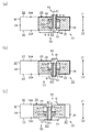
図2(b)を参照して、位相固定機構40及び進角規制機構50の構成について詳述する。なお、図2(b)は図2(a)のDA−DA線に沿う断面構造を示す。
図2(b)に示されるように、位相固定機構40は、ベーン36に設けられた規制ピン60と、同じくベーン36に設けられて油圧機構7により潤滑油が供給及び排出される作動室66と、また同じくベーン36に設けられて規制ピン60を一方向に押すばね64と、カバー34のカバー壁面34Aに設けられたロック穴41とに構成されている。
With reference to FIG.2 (b), the structure of the
As shown in FIG. 2B, the
進角規制機構50は、ベーン36に設けられた収納室36Aに収納される規制ピン60と、収納室36A内であって規制ピン60の一部である区画体62とベーン36とに区画されて油圧機構7により潤滑油が供給及び排出される作動室66と、また同じく収納室36A内の区画体62を挟んで対面側となるばね室65に設けられて規制ピン60を一方向に押すばね64と、ハウジングロータ31のロック穴41と対面するハウジング本体32のスプロケット壁面33Aに設けられた規制溝51とで構成されている。
The advance
このように、位相固定機構40及び進角規制機構50は共通する単一の規制ピン60をそれぞれの構成要素とするものであるため、一方の機構において規制ピン60が機能するときには他方の機構において同ピン60は機能しない。
Thus, since the
規制ピン60は、軸方向に連通孔63を備えるピン本体61と、作動室66の圧力が作用する区画体62を備えている。規制ピン60は、作動室66の潤滑油の力とばね64の力との関係に基づいて、ベーン36内に収容された位置(以下、「収容位置P0」)と、ベーン36からスプロケット壁面33Aに向けて突出した位置(以下、「第2突出位置P2」)及びベーン36からカバー壁面34Aに向けて突出した位置(以下、「第1突出位置P1」)との間で移動する。作動室66の油圧は、規制ピン60に対してスプロケット壁面33A方向に作用する。ばね64の力は、規制ピン60に対してカバー壁面34A方向に作用する。以降では、収容位置P0及び第1突出位置P1から第2突出位置P2に向かう方向を「第2突出方向Z2」とし、収容位置P0及び第2突出位置P2から第1突出位置P1に向かう方向を「第1突出方向Z1」とする。
The
また、ピン本体61のスプロケット側先端部61Bとスプロケット壁面33Aとの間の空間及び、ピン本体61のカバー側先端部61Aとカバー壁面34Aとの間の空間は連通孔63を介して連通している。
The space between the
油圧機構7により作動室66に対して潤滑油が排出されている、すなわち作動室66に対する潤滑油の状態が排出状態にあるとき、ばね64によるカバー壁面34A方向の力により、規制ピン60に対してはこれを第1突出方向Z1に動作させようとする力が生じる。そして、作動室66の潤滑油による規制溝51方向の力がばね64による第1突出方向Z1の力を下回るようになる。これにより、規制ピン60に対してはこれを第1突出方向Z1に動作させようとする力が生じる。そしてこの状態のもとで、ハウジング本体32に対するベーンロータ35の回転位相が最遅角位相PMINにあるとき、すなわち規制ピン60とロック穴41との周方向の位置が一致しているとき、規制ピン60がベーン36から突出してロック穴41にはめ込まれる。これにより、規制ピン60とロック穴41との係合を通じてハウジングロータ31とベーンロータ35とが互いに固定されるため、これらの相対的な回転位相は最遅角位相PMINに保持される。
When the lubricating oil is discharged to the working
一方、油圧機構7により作動室66から潤滑油が供給されて作動室66が潤滑油により満たされるとき、すなわち作動室66に対する潤滑油の状態が供給状態にあるとき、作動室66の潤滑油による第2突出方向Z2の力がばね64による第1突出方向Z1の力を上回るようになる。これにより、規制ピン60に対してはこれを第2突出方向Z2に動作させようとする力が生じる。そして規制ピン60がロック穴41にはめ込まれた状態のもとで、規制ピン60に対して第2突出方向Z2の力が作用するとき、規制ピン60がロック穴41から離脱して第2突出方向Z2に突出してスプロケット壁面33Aに突き当たる。これにより、規制ピン60とロック穴41との係合によるハウジング本体32とベーンロータ35との固定が解除されて、ハウジング本体32に対するベーンロータ35の回転が許容される。
On the other hand, when the lubricating oil is supplied from the working
図3を参照して、バルブタイミング可変機構30と油圧機構7との間における潤滑油の流通態様について説明する。なお同図は、これら装置の間における油路の構成を模式的に示している。
With reference to FIG. 3, the flow mode of the lubricating oil between the variable
油圧機構7は、ベーンロータ35の駆動を制御する第1油圧制御機構70と、規制ピン60の駆動を制御する第2油圧制御機構80とから構成されている。
第1油圧制御機構70は、作動油を遅角室39に供給又は排出する遅角室油路72と、進角室38に作動油を供給又は排出する進角室油路73と、作動油を油路に供給する第1供給油路74と、油路からの作動油を排出する第1排出油路75と、作動油の供給及び排出及び保持を制御する第1油圧制御弁71とを備えている。また、第1供給油路74には、オイルパン12からの作動油を吐出するオイルポンプ17が設けられている。
The
The first
第1油圧制御弁71は、第1供給油路74及び第1排出油路75と進角室油路73及び遅角室油路72との接続状態を切り替えることにより、進角室38及び遅角室39に対する潤滑油の供給状態を変更する。
The first
第1油圧制御弁71の制御により、遅角室油路72が第1排出油路75に接続されるとともに進角室油路73が第1供給油路74に接続されると、進角室油路73を介して進角室38に作動油が供給され且つ遅角室油路72を介して遅角室39の作動油が排出される。そしてこのとき、ベーンロータ35がハウジングロータ31に対して進角位相側に回転し、バルブタイミングINVTが進角側に変化する。
When the retard
第1油圧制御弁71の制御により、遅角室油路72が第1供給油路74に接続されるとともに進角室油路73が第1排出油路75と接続されると、進角室油路73を介して進角室38の作動油が排出され且つ遅角室油路72を介して遅角室39に作動油が供給される。そしてこのとき、ベーンロータ35がハウジングロータ31に対して遅角位相側に回転し、バルブタイミングINVTが遅角側に変化する。
When the retard
第2油圧制御機構80は、作動室66に作動油を供給する作動室供給油路82と、作動室66から作動油を排出する作動室排出油路83を備えている。さらに、第2油圧制御機構80は、オイルパン12から作動室66の作動油を供給する第2供給油路84と、油路からの作動油を排出する第2排出油路85と作動油の供給及び排出及び保持を制御する第2油圧制御弁81とを備えている。
The second
第2油圧制御弁81は、作動室供給油路82及び作動室排出油路83と第2供給油路84及び第2排出油路85の接続状態を切り替えることにより、作動室66対する潤滑油の供給状態を変更する。
The second
そして、規制ピン60を第2突出方向Z2に突出させるとき、すなわち進角規制機構50の規制溝51に規制ピン60をはめ込むときには、第2油圧制御弁81の駆動により、作動室供給油路82を第2供給油路84に接続して作動室66に作動油を供給する。一方、規制ピン60を第1突出方向Z1に突出させるとき、すなわち位相固定機構40のロック穴41に規制ピン60をはめ込むときには、第2油圧制御弁81の駆動により、作動室排出油路83を第2排出油路85に接続して作動室66から作動油を排出する。
When the
図4に、バルブタイミング可変機構30の断面構造を模式的に示す。なお、同図は、図2(a)のDB−DB線に沿うバルブタイミング可変機構30の断面構造を平面上に展開したものについて、これを模式的に示している。
FIG. 4 schematically shows a cross-sectional structure of the variable
図4に示されるように、スプロケット33のベーン収容室37は、ベーン36により、進角室38及び遅角室39に区画されている。そして、カバー壁面34Aにはロック穴41が、スプロケット壁面33Aには規制ピン60の周方向の軌跡に沿う態様で規制溝51が形成されている。
As shown in FIG. 4, the
図4(a)に示されるように、ベーン36すなわちベーンロータ35の回転位相が最遅角位相PMINにあり且つ作動室66の作動油が排出されているとき、規制ピン60がベーン36から第1突出方向Z1方向に突出して第1突出位置P1にあることによりそのカバー側先端部61Aはロック穴41にはめ込まれた状態にある。これにより、ベーンロータ35とハウジングロータ31との相対回転位相が固定されて、バルブタイミングINVTは最遅角INVTminに固定される。
As shown in FIG. 4A, when the rotational phase of the
そして、バルブタイミング可変機構30が図4(a)の状態にあるときに作動室66に作動油が供給されたとすると、この作動油の供給に基づく規制ピン60の移動によりバルブタイミング可変機構30は図4(b)の状態に移行する。
If the hydraulic oil is supplied to the working
図4(b)に示されるように、ベーンロータ35の回転位相が最遅角位相PMINにあり且つ作動室66に油圧が供給されているとき、規制ピン60がベーン36から第2突出方向Z2方向に突出して第2突出位置P2に移動することによりそのスプロケット側先端部61Bは規制溝51にはめ込まれた状態にある。そして、図4(b)の状態からベーンロータ35が進角することにより図4(c)に移行する。
As shown in FIG. 4B, when the rotational phase of the
図4(c)に示されるように、ベーンロータ35の回転位相が最遅角位相PMINと進角規制位相PMDLとの間にあり且つ作動室66に油圧が供給されているとき、規制ピン60がベーン36から第2突出方向Z2方向に突出して第2突出位置P2にあることによりそのスプロケット側先端部61Bは規制溝51にはめ込まれた状態にある。そして、図4(c)の状態からベーンロータ35がさらに進角することによりバルブタイミング可変機構30の状態は図5(a)に移行する。
As shown in FIG. 4C, when the rotational phase of the
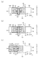
図5(a)に示されるように、規制ピン60が規制溝51にはめ込まれた状態にて最遅角位相PMINまで進角したとき、規制ピン60と規制溝51の端面との係合によりベーンロータ35のそれ以上の進角が規制される。このとき、バルブタイミングINVTは進角規制角INVTmdlに維持される。すなわち、規制ピン60が規制溝51にはめ込まれた状態にあるとき、ベーンロータ35とハウジングロータ31との相対回転範囲が最遅角位相PMINから進角規制位相PMDLの範囲に制限されて、バルブタイミングINVTが進角規制角INVTmdlより進角することは規制される。
As shown in FIG. 5A, when the
バルブタイミング可変機構30が図5(a)の状態にあるときに作動室66の作動油が排出されたとすると、この作動油の排出に基づく規制ピン60の移動によりバルブタイミング可変機構30は図5(b)の状態に移行する。
If the hydraulic oil in the working
図5(b)に示されるように、ベーンロータ35の回転位相が進角規制位相PMDLにあり且つ作動室66の作動油が排出されているとき、規制ピン60がベーン36から第1突出方向Z1に突出しようとする状態にあるもののカバー壁面34Aに突き当たるため収容位置P0に保持される。これにより、ベーンロータ35とハウジングロータ31との進角側または遅角側への相対回転位相が許容される。そして、図5(b)の状態からベーンロータ35が進角規制位相PMDLを超えて進角することによりバルブタイミング可変機構30の状態は図5(c)に移行する。
As shown in FIG. 5B, when the rotation phase of the
図5(c)に示されるように、規制ピン60がベーン36に収容された状態にあるとき、ベーンロータ35は最進角位相PMAXまで進角することが許容される。なお、ベーンロータ35の回転位相が進角規制位相PMDLよりも進角側にあるときには、作動室66への作動油の給排状態にかかわらず規制ピン60は収容位置P0に保持される。
As shown in FIG. 5C, when the
ところで、図6(a)に示されるようにベーンロータ35が最遅角位相PMINと進角規制位相PMDLとの間の位相であって、進角規制位相PMDLに近い位置にあるとき、規制溝51の最も進角室38側の部分と進角室38とが連通部37Aにおいて連通する。このとき、進角室38に供給される作動油が規制溝51内に流通する。このため、この作動油は規制ピン60に対して第1突出方向Z1の力を付与する。このとき、規制ピン60に作用する圧力及び力について図6(b)を参照して詳述する。
By the way, as shown in FIG. 6A, when the
規制ピン60のピン本体61のスプロケット側先端部61Bには、規制溝51の作動油により第1突出方向Z1の圧力PO1が作用する。カバー側先端部61Aには、カバー側先端部61Aとカバー壁面34Aとの間に形成される空間37B内の作動油により第2突出方向Z2の圧力PO2が作用する。
The pressure PO1 in the first protruding direction Z1 is applied to the
区画体62のスプロケット側面62Aには、作動油に基づく圧力は作用しない。カバー側面62Bには、作動室66の作動油により第2突出方向Z2の圧力PPが作用する。なお、区画体62のスプロケット側面62Aには、ばね64に基づく力FSが付与されている。
The pressure based on the hydraulic oil does not act on the
従って、規制ピン60に作用する力は以下のようになる。
第1突出方向Z1には圧力PO1に基づく力F1及びばねの力FSが作用する。
第2突出方向Z2方向には圧力PO2に基づく力F2及びPPに基づく力FPが作用する。
Accordingly, the force acting on the
In the first protruding direction Z1, a force F1 based on the pressure PO1 and a spring force FS are applied.
A force F2 based on the pressure PO2 and a force FP based on PP act on the second protruding direction Z2.
ここで、規制ピン60には連通孔63が設けられているため、作動油は規制ピン60のスプロケット側先端部61Bとカバー側先端部61Aとの間で流通するため、圧力PO1と圧力PO2とは等しくなっている。このため力F1と力F2は相殺されることになる。
Here, since the
従って、規制ピン60の位置は、ばねの力FSと作動室66内の圧力PPによる力FPとに基づいて決定される。
ちなみに連通孔63を設けない場合には、進角室38と規制溝51とが連通部37Aによって連通して進角室38の作動油が規制溝51に流入したとき、ピン本体61のスプロケット側先端部61Bには進角室38から流入してきた作動油に基づく圧力によって規制ピン60に第1突出方向Z1への力が付与されることになる。このため、規制ピン60は第1突出方向Z1へと移動して収容位置P0に保持されることになり、ベーンロータ35が進角規制位相PMDLを超えて進角側に移動することを許容してしまう。一方、本実施形態では規制ピン60に連通孔63を設けているため、進角室38から流入した作動油に基づいて規制ピン60が収容位置P0に保持されることは抑制される。
Accordingly, the position of the
Incidentally, when the
図7を参照して、バルブタイミングINVT及び最大バルブリフト量INVLに基づく規制機構4の制御態様について、その一例を説明する。
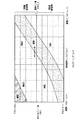
バルブ開閉特性協調制御においては、目標タイミングINVTT及び目標最大リフト量INVLTにより定められるバルブ開閉特性の要求値VTVLについて、これがバルブタイミングINVT及び最大バルブリフト量INVLにより定められるバルブ開閉特性領域上のいずれにあるかに基づいて規制機構4の制御が行われる。ここで、バルブ開閉特性領域は次の領域A〜領域Fに区分される。
With reference to FIG. 7, an example of the control mode of the restriction mechanism 4 based on the valve timing INVT and the maximum valve lift amount INVL will be described.
In the valve opening / closing characteristic cooperative control, the valve opening / closing characteristic request value VTVL determined by the target timing INVTT and the target maximum lift amount INVLT is not included in the valve opening / closing characteristic region determined by the valve timing INVT and the maximum valve lift amount INVL. The restriction mechanism 4 is controlled based on whether there is any. Here, the valve opening / closing characteristic region is divided into the following regions A to F.
領域Aは、最大バルブリフト量INVLが規制リフト量INVLXよりも大きく、且つバルブタイミングINVTが進角規制角INVTmdlよりも遅角側にあるバルブ開閉特性領域を示す。 Region A shows a valve opening / closing characteristic region in which the maximum valve lift amount INVL is larger than the regulated lift amount INVLX and the valve timing INVT is on the retard side with respect to the advance angle regulating angle INVTmdl.
領域Bは、最大バルブリフト量INVLが規制リフト量INVLXよりも大きく、且つバルブタイミングINVTが進角規制角INVTmdlよりも進角側にあるバルブ開閉特性領域を示す。 Region B shows a valve opening / closing characteristic region in which the maximum valve lift amount INVL is larger than the regulated lift amount INVLX and the valve timing INVT is on the advance side with respect to the advance angle regulated angle INVTmdl.
領域Cは、最大バルブリフト量INVLが規制リフト量INVLXよりも小さく、且つバルブタイミングINVTが進角規制角INVTmdlよりも遅角側にあるバルブ開閉特性領域を示す。 Region C shows a valve opening / closing characteristic region in which the maximum valve lift amount INVL is smaller than the regulated lift amount INVLX and the valve timing INVT is on the retard side with respect to the advance angle regulating angle INVTmdl.
領域Dは、最大バルブリフト量INVLが規制リフト量INVLXよりも小さく、且つバルブタイミングINVTが進角規制角INVTmdlより進角側にあるバルブ開閉特性領域を示す。 Region D shows a valve opening / closing characteristic region in which the maximum valve lift amount INVL is smaller than the regulated lift amount INVLX and the valve timing INVT is on the advance side with respect to the advance angle regulated angle INVTmdl.
領域Eは、上記領域Bのうちの進角側且つ大リフト側の領域であり、最大バルブリフト量INVL及びバルブタイミングINVTが当該領域Eに設定されているときにバブルスタンプが生じるバルブ開閉特性領域を示す。 The region E is an advance angle side and large lift side region of the region B, and a valve opening / closing characteristic region in which a bubble stamp occurs when the maximum valve lift amount INVL and the valve timing INVT are set in the region E. Indicates.
領域Fは、機関運転状態に基づくバルブ開閉特性の変更が行われるときの基本的な使用領域を示す。すなわち、通常の機関運転状態においては、機関負荷及び機関回転速度等の変化に基づいて当該領域F内にてバルブ開閉特性が変化するよう可変動弁装置3の制御が行われる。 A region F indicates a basic use region when the valve opening / closing characteristic is changed based on the engine operating state. That is, in a normal engine operating state, the variable valve gear 3 is controlled so that the valve opening / closing characteristics change in the region F based on changes in the engine load, the engine speed, and the like.
要求値VTVLが領域F内にて変化するとき、規制機構4は次のように駆動する。
要求値VTVLが領域Aにあるとき、進角規制機構50が係合状態に設定され、これによりバルブタイミングINVTの変更可能範囲が最遅角INVTminから進角規制角INVTmdlまでの間に制限される。またこの状態において、ベーンロータ35の回転位相が進角規制位相PMDLに達したとき、進角規制機構50によりベーンロータ35のそれ以上の進角側への回転が規制される。
When the required value VTVL changes in the region F, the restriction mechanism 4 is driven as follows.
When the required value VTVL is in the region A, the advance
要求値VTVLの属する領域が領域Aから領域Cに変化するとき、進角規制機構50が係合状態から解除状態に操作され、これによりバルブタイミングINVTの変更可能範囲は最遅角INVTminから最進角INVTmaxまでの間に拡大される。
When the region to which the required value VTVL belongs changes from the region A to the region C, the advance
要求値VTVLの属する領域が領域Cから領域Dに変化するとき、進角規制機構50の解除状態が保持され、これによりバルブタイミングINVTの変更可能範囲は最遅角INVTminから最進角INVTmaxまでの間に維持される。
When the region to which the requested value VTVL belongs changes from the region C to the region D, the release state of the advance
なお、領域Bのうちバルブスタンプが生じるおそれのある部分は領域Eに限られるものの、ここでは実際のバルブタイミングINVT及び最大バルブリフト量INVLが領域Bに属することのないように可変動弁装置3の制御が行われる。 Note that, in the region B, the portion where the valve stamp may be generated is limited to the region E, but here, the variable valve gear 3 so that the actual valve timing INVT and the maximum valve lift amount INVL do not belong to the region B. Is controlled.
以上説明した本実施形態によれば以下の効果を奏することができる。
(1)本実施形態の可変動弁装置3の規制機構4は、ロック穴41と規制溝51とを含めて構成されている。ロック穴41にはハウジングロータ31に設けられて、ベーン36に収容される収容位置P0とベーンロータ35から突出した第1突出位置P1及び第2突出位置P2との間で移動する規制ピン60が、第1突出位置P1にある規制ピン60がはめ込まれる。規制溝51はハウジングロータ31に設けられて第2突出位置P2にある規制ピン60がはめ込まれる。そしてこの可変動弁装置3は、規制ピン60がロック穴41にはめ込まれた状態にあるときにハウジングロータ31とベーンロータ35との相対回転位相が固定され、規制ピン60が規制溝51にはめ込まれた状態にあるときにハウジングロータ31とベーンロータ35との相対回転範囲が最遅角位相PMINから最進角位相PMAXまでの範囲よりも小さい範囲に制限されるようにしている。
According to this embodiment described above, the following effects can be obtained.
(1) The restriction mechanism 4 of the variable valve operating apparatus 3 according to the present embodiment includes a
一つの規制ピン60を第1及び第2突出位置P2においてロック穴41及び規制溝51とはめ込むことによりベーンロータ35のハウジングロータ31に対する回転を禁止もしくは規制しているため、一つの規制ピン60でベーンロータ35のハウジングロータ31の相対回転位相の固定及び相対回転範囲の制限をすることができるようになる。従って、バルブスタンプを抑制する機能及びバルブタイミングINVTを固定する機能を備えるとともに、これら機能を実現するための構造の複雑化を抑制することができるようになる。
Since one
(2)本実施形態では、規制ピン60が規制溝51にはめ込まれた状態にあるときにハウジングロータ31とベーンロータ35との相対回転の範囲が最進角位相PMAXよりも遅角側にある進角規制位相PMDLから最遅角位相PMINまでの範囲に制限されるようにしている。
(2) In this embodiment, when the
規制ピン60が規制溝51とはめ込まれた状態にあるとき、ベーンロータ35は、ハウジングロータ31に対して進角規制位相PMDLを超えて進角側に回転することが規制される一方、ベーンロータ35が遅角側に回転するときには最遅角位相PMINに至るまでその回転が許容される。
When the
(3)本実施形態では、規制ピン60がロック穴41にはめ込まれた状態にあるときにハウジングロータ31に対するベーンロータ35の回転位相が最遅角位相PMINに固定されるようにしている。
(3) In the present embodiment, the rotational phase of the
規制ピン60がロック穴41と係合した状態にあるとき、ベーンロータ35は、最遅角位相PMINにてハウジングロータ31に対して固定される。
(4)本実施形態では、規制ピン60は、ベーンロータ35に対して同回転体の軸方向の一方に突出して収容位置から第1突出位置P1に移動し、ベーンロータ35に対して同回転体の軸方向の他方に突出して収容位置P0から第2突出位置P2に移動するようにしている。また、可変動弁装置3は、バルブタイミング可変機構30及び規制機構4のそれぞれに対する作動油の給排を通じてこれら機構を操作する油圧機構7をさらに備えるものである。規制機構4には、油圧機構7から供給される作動油により規制ピン60を第2突出位置P2に向けて押す作動室66と、規制ピン60を第1突出位置P1に向けて押すばね64とが設けられる。そして、これら作動室66及びばね64の力の関係により規制ピン60を収容位置P0と第1突出位置P1及び第2突出位置P2の間で移動させるようにしている。
When the
(4) In the present embodiment, the
可変動弁装置3の油圧機構7を通じて作動室66に供給される作動油及びばね64がそれぞれ規制ピン60に対して第1突出方向Z1及び第2突出方向Z2への力を付与するため、規制ピン60の移動及び位置の保持を実現するために新たに油圧機構7を新たに設ける必要がない。
Since the hydraulic oil and the
(5)本実施形態では、バルブタイミング可変機構30は、ベーンロータ35の軸方向において同ロータ35を介して互いに対向するカバー34及びスプロケット33のそれぞれにロック穴41及び規制溝51が設けられている。そして、規制ピン60は、カバー側先端部61Aとロック穴41が設けられるカバー34との間にある空間と規制溝51とを連通する連通孔63がピン本体61に設けられるようにしている。
(5) In the present embodiment, the variable
規制ピン60が第2突出位置P2に突出し、規制溝51にはめ込まれた状態において、作動油が給排される進角室38と規制溝51とが連通することがある。このとき、進角室38の作動油が規制溝51内に流入すると、規制ピン60に対してこの流入した作動油に基づく力が付与されてしまうことになる。すると、規制ピン60がこの力に基づいて第1突出位置P1側に移動してしまうおそれが生じる。
In a state where the
そこで本実施形態では、規制ピン60に連通孔を設けてカバー側先端部61Aとスプロケット側先端部61Bとの間で作動油を流通させるようにしているため、作動油の進角室38と規制溝51が連通したとしても、規制溝51に流入した作動油に基づいて規制ピン60が移動してしまうことが抑制される。従って、規制ピン60の位置を好適に保持できるようになる。
Therefore, in the present embodiment, the
(6)本実施形態の可変動弁装置3は、吸気バルブ21の最大バルブリフト量を変更するバルブリフト量可変機構90をさらに備えるものである。そして、規制機構4は、吸気バルブ21の最大バルブリフト量INVLが規制リフト量INVLXよりも大きい値に設定されることに基づいて、ハウジングロータ31とベーンロータ35との相対回転範囲を最遅角位相PMINから最進角位相PMAXまでの範囲よりも小さい範囲に制限するようにしている。
(6) The variable valve operating apparatus 3 of the present embodiment further includes a valve lift amount
ベーンロータ35がハウジングロータ31に対して進角規制位相PMDLを超えて進角することを規制する規制機構4について、規制ピン60をハウジングロータ31またはベーンロータ35に収容する動作がこれら回転体の相対的な回転により妨げられることを抑制することができるようになる。
Regarding the restriction mechanism 4 that restricts the
(その他の実施形態)
なお、本発明の実施態様は上記実施形態に限られるものではなく、例えば以下に示す態様をもって実施することもできる。
(Other embodiments)
The embodiment of the present invention is not limited to the above-described embodiment, and can be carried out, for example, in the following manner.
・上記実施形態では、規制機構4の位相固定機構40としてベーンロータ35の回転位相を最遅角位相PMINに固定するものを採用したが、最遅角位相PMINと最進角位相PMAXとの間にある所定の中間位相に固定する位相固定機構40を採用することもできる。
In the above embodiment, the
・上記実施形態では、進角規制機構50は最進角INVTmaxよりも遅角側の進角規制角INVTmdlに対応する進角規制位相PMDLと最遅角INVTminに対応する最遅角位相PMINとの間でスプロケット33に対するベーンロータ35の回転位相を規制したが、進角規制機構50による規制範囲はこれに限られるものではない。例えば、最進角INVTmaxに対応する最進角位相PMAXと最遅角位相PMINよりも進角側にある所定位相との範囲にベーンロータ35の回転範囲を制限することもできる。あるいは、最進角位相PMAXよりも遅角側の位相と、これよりもさらに遅角側の位相且つ最遅角位相PMINよりも進角側の位相との間の範囲にベーンロータ35の回転範囲を制限することもできる。
In the above-described embodiment, the advance
・上記実施形態では、吸気バルブ21のバルブタイミングINVTを変更する可変動弁装置3について本発明を適用したが、排気バルブ25のバルブタイミング変更する可変動弁装置についても同様に本発明を適用することができる。排気バルブにおいては、遅角側の位相においてバルブスタンプが起きることが懸念される。すなわちこの場合、排気バルブの最大バルブリフト量が所定のバルブリフト量を超えるときに、遅角規制位相を超えてベーンロータが遅角側に回転することを規制する規制機構と規制ピンとが係合する構成とする。これにより、バルブタイミング可変機構においてベーンロータが遅角規制位相に対応する回転位相を超えて回転することが規制されるため、排気バルブとピストンとの衝突が生じることは回避されるようになる。
In the above embodiment, the present invention is applied to the variable valve operating apparatus 3 that changes the valve timing INVT of the
・上記実施形態では、ピン本体61に連通孔63を設けることにより、進角室38と規制溝51との連通時に進角室38から規制溝51に流入した作動油に起因した規制ピン60の移動が抑制されるようにしたが、例えば次の各構成により同様の効果を奏することもできる。
In the above embodiment, by providing the
(A)図5(b)にて示されるピン本体61のカバー側先端部61Aの面すなわち、進角室38から流入した作動油に基づくカバー壁面34A方向への力を受ける面の面積を、区画体62のスプロケット側面62Aの面積に対して小さなものとする。すると、作動室66の作動油に基づく圧力に対して進角室38から流入した作動油に起因する圧力が小さなものとなるため、規制ピン60の第1突出方向Z1への移動が抑制される。
(A) The area of the cover-
(B)作動室66に供給する作動油の量を調整することで規制ピン60の位置を制御する構成とする。すなわち、進角室38から規制溝51内への作動油の流入があるときには、流入する作動油の圧力に基づいて作動室66へ作動油を供給する。
(B) The position of the
・上記実施形態では、規制ピン60に連通孔63を設けたが、連通孔63を省略することもできる。この場合にも、規制溝51の位置や大きさの変更を通じて収容室37と規制溝51とが連通しない構成することにより、実施形態の(5)以外の効果を得ることはできる。
In the above embodiment, the
・上記実施形態では、ベーン36の周方向中央に規制ピン60を設けたが、中央に限らずいずれの位置であっても良い。
・上記実施形態では、カバー壁面34Aにロック穴41を設け、スプロケット壁面33Aに規制溝51を設けたが、カバー壁面34Aに規制溝51を設け、スプロケット壁面33Aにロック穴41を設ける構成としても良い。
In the above embodiment, the
In the above embodiment, the
・上記実施形態では、収納室36Aのカバー壁面34A側に作動室66を設けるようにしたが、スプロケット壁面33A側に作動室66を設けるようにしても良い。このような構成のときは、作動室66への作動油の供給及び排出状態を規制ピン60とロック穴41及び規制溝51との係合動作と整合させることで、上記実施形態に準じた効果を得ることができる。
In the above embodiment, the working
・上記実施形態では、バルブタイミング可変機構及びバルブリフト量可変機構を併せて備える可変動弁装置に対して本発明を適用したが、同装置からバルブリフト量可変機構を省略したものについて本発明を適用することもできる。 In the above embodiment, the present invention is applied to a variable valve operating apparatus that includes both a variable valve timing mechanism and a variable valve lift amount mechanism. However, the present invention is applied to a device that omits the variable valve lift amount mechanism from the same device. It can also be applied.
この場合には、バルブリフト量可変機構が省略されることにより、最大バルブリフト量INVLに基づく規制ピンの制御がなされなくなるとはいえ、その他の要求に基づいて規制ピンによるバルブタイミングINVTの規制を行うことはできる。例えば、バルブオーバーラップの大きさを所定期間よりも大きいものに制限すべく制御上にてバルブタイミングINVTの遅角量の上限値が設定される場合において、このバルブオーバーラップの制限を補助すべく規制ピンを突出した状態に維持することが考えられる。 In this case, although the control of the restriction pin based on the maximum valve lift amount INVL is not performed by omitting the valve lift amount variable mechanism, the restriction of the valve timing INVT by the restriction pin is restricted based on other requirements. Can be done. For example, when the upper limit value of the retard amount of the valve timing INVT is set in the control so as to limit the size of the valve overlap to a value larger than a predetermined period, this limit of the valve overlap should be assisted. It is conceivable to keep the regulating pin in a protruding state.
この構成によれば、通常ではバルブタイミングINVTが遅角量の上限値を超えて遅角されることは制御上にて規制されるものの、何らかの理由によりバルブタイミングINVTが上限値を超えて遅角側に変更されることもある。このとき、遅角量の上限値が遅角規制位相に対応する規制角よりも進角側に設定されている場合には、上述のようにバルブタイミングINVTが遅角量の上限値を超えたとしても、規制角を超えて遅角することは規制ピンにより制限されるようになる。 According to this configuration, normally, the valve timing INVT is retarded beyond the upper limit value of the retard amount in terms of control, but for some reason, the valve timing INVT exceeds the upper limit value and the retard angle is retarded. It may be changed to the side. At this time, when the upper limit value of the retard amount is set to an advance side with respect to the restriction angle corresponding to the retard restriction phase, the valve timing INVT exceeds the upper limit value of the retard amount as described above. Even so, retarding beyond the regulation angle is limited by the regulation pin.
このように、規制ピンを突出状態に維持する構成を採用した場合には、バルブタイミングINVTが遅角量の上限値を超えたときにこれを上回る量は規制ピンによる規制が行われない場合よりも小さくなる。すなわち、バルブリフト量可変機構を省略した構成においても、規制ピンによるバルブタイミングINVTの規制を行うことの意義はある。 Thus, when the structure which maintains a control pin in a protrusion state is employ | adopted, when valve timing INVT exceeds the upper limit of retardation amount, the amount exceeding this is the case where control by a control pin is not performed. Becomes smaller. In other words, even in a configuration in which the valve lift amount variable mechanism is omitted, it is meaningful to regulate the valve timing INVT by the regulation pin.
そして、上記にて例示した構成をはじめとして最大バルブリフト量からの要求とは別の要求に基づいて規制ピンを操作するものについて、これに対して本発明を適用した当該変形例によれば、上記実施形態と同様に規制機構の構成を簡略化することができる。 And about what operates a regulation pin based on the demand different from the demand from the maximum valve lift amount including the composition illustrated above, according to the modification to which the present invention is applied, Similar to the above embodiment, the configuration of the regulating mechanism can be simplified.
・結局のところ、ハウジングとベーンロータとの相対回転の範囲を最遅角位相から最進角位相までの範囲よりも制限する規制機構を備える可変動弁装置であればいずれのものに対しても本発明を適用することは可能であり、その場合にも上記実施形態の効果に準じた効果が奏せられるようになる。 ・ After all, this is applicable to any variable valve operating system that has a restriction mechanism that limits the range of relative rotation between the housing and the vane rotor more than the range from the most retarded phase to the most advanced angle phase. The invention can be applied, and even in that case, an effect according to the effect of the above-described embodiment can be achieved.
1…内燃機関、10…機関本体、11…シリンダブロック、12…オイルパン、13…シリンダヘッド、14…燃焼室、15…ピストン、16…クランクシャフト、17…オイルポンプ、21…吸気バルブ、22…吸気カムシャフト、22C…吸気カム、23…ロッカアーム、24…ラッシュアジャスタ、25…排気バルブ、26…排気カムシャフト、3…可変動弁装置、30…バルブタイミング可変機構、31…ハウジングロータ(入力回転体)、31A…区画壁、32…ハウジング本体、33…スプロケット(第2部位)、33A…スプロケット壁面、34…カバー(第1部位)、34A…カバー壁面、35…ベーンロータ(出力回転体)、36…ベーン、36A…収納室、37…ベーン収容室、37A…連通部、37B…空間、38…進角室、39…遅角室、4…規制機構、40…位相固定機構、41…ロック穴(規制穴)、50…進角規制機構、51…規制溝、60…規制ピン(規制体)、61…ピン本体(規制本体)、61A…カバー側先端部、61B…スプロケット側先端部、62…区画体(規制区画体)、62A…スプロケット側面、62B…カバー側面、63…連通孔、64…ばね、65…ばね室、66…作動室、7…油圧機構、70…第1油圧制御機構、71…第1油圧制御弁、72…遅角室油路、73…進角室油路、74…第1供給油路、75…第1排出油路、80…第2油圧制御機構、81…第2油圧制御弁、82…作動室供給油路、83…作動室排出油路、84…第2供給油路、85…第2排出油路、90…バルブリフト量可変機構、91…コントロールシャフト、92…アームアッシ、93…入力アーム、94…出力アーム、100…制御装置、110…電子制御装置、111…クランクポジションセンサ、112…カムポジションセンサ。
DESCRIPTION OF SYMBOLS 1 ... Internal combustion engine, 10 ... Engine main body, 11 ... Cylinder block, 12 ... Oil pan, 13 ... Cylinder head, 14 ... Combustion chamber, 15 ... Piston, 16 ... Crankshaft, 17 ... Oil pump, 21 ... Intake valve, 22 Intake camshaft, 22C ... Intake cam, 23 ... Rocker arm, 24 ... Rush adjuster, 25 ... Exhaust valve, 26 ... Exhaust camshaft, 3 ... Variable valve gear, 30 ... Variable valve timing mechanism, 31 ... Housing rotor (input) Rotating body), 31A ... partition wall, 32 ... housing body, 33 ... sprocket (second part), 33A ... sprocket wall surface, 34 ... cover (first part), 34A ... cover wall surface, 35 ... vane rotor (output rotating body) , 36 ... vane, 36A ... storage room, 37 ... vane storage room, 37A ... communication part, 37B ... space, 38 ... Corner chamber, 39 ... retard chamber, 4 ... regulating mechanism, 40 ... phase locking mechanism, 41 ... lock hole (regulating hole), 50 ... advance angle regulating mechanism, 51 ... regulating groove, 60 ... regulating pin (regulator), 61 ... Pin body (restricted body), 61A ... cover-side tip, 61B ... sprocket-side tip, 62 ... compartment (regulator compartment), 62A ... sprocket side, 62B ... cover side, 63 ... communication hole, 64 ... Spring, 65 ... Spring chamber, 66 ... Working chamber, 7 ... Hydraulic mechanism, 70 ... First hydraulic control mechanism, 71 ... First hydraulic control valve, 72 ... Delay chamber oil passage, 73 ... Advance chamber oil passage, 74 DESCRIPTION OF SYMBOLS ... 1st supply oil path, 75 ... 1st discharge oil path, 80 ... 2nd hydraulic control mechanism, 81 ... 2nd hydraulic control valve, 82 ... Working chamber supply oil path, 83 ... Working chamber discharge oil path, 84 ...
Claims (11)
前記規制機構は、前記出力回転体に収容される収容位置と前記出力回転体から突出した第1の突出位置及び第2の突出位置との間で移動する規制体と、前記入力回転体に設けられて前記第1の突出位置にある前記規制体がはめ込まれる規制穴と、前記入力回転体に設けられて前記第2の突出位置にある前記規制体がはめ込まれる規制溝とを含めて構成されるものであり、
当該可変動弁装置は、前記規制体が前記規制穴にはめ込まれた状態にあるときに前記入力回転体と前記出力回転体との相対回転位相が固定され、前記規制体が前記規制溝にはめ込まれた状態にあるときに前記入力回転体と前記出力回転体との相対回転範囲が最遅角位相から最進角位相までの範囲よりも小さい範囲に制限されるものである
ことを特徴とする内燃機関の可変動弁装置。 The relative rotation phase between the input rotating body linked to the crankshaft and the output rotating body linked to the camshaft of the intake valve or exhaust valve as the engine valve is operated between the most retarded phase and the most advanced angle phase. The variable valve timing mechanism that changes the valve timing of the engine valve between the most advanced angle and the most retarded angle, and the range of relative rotation between the input rotator and the output rotator is the most advanced from the most retarded phase. In a variable valve operating apparatus for an internal combustion engine, including a restriction mechanism that restricts more than the range up to the angular phase,
The restricting mechanism is provided on the input rotator, a restricting body that moves between a housing position accommodated in the output rotator and a first projecting position and a second projecting position projecting from the output rotator. And a restriction hole into which the restriction body in the first projecting position is fitted, and a regulation groove provided in the input rotating body and into which the regulation body in the second projecting position is fitted. And
In the variable valve device, the relative rotational phase between the input rotating body and the output rotating body is fixed when the regulating body is fitted in the regulating hole, and the regulating body is fitted in the regulating groove. The relative rotation range between the input rotator and the output rotator is limited to a range smaller than the range from the most retarded phase to the most advanced angle phase. A variable valve operating device for an internal combustion engine.
前記規制体が前記規制溝にはめ込まれた状態にあるときに前記入力回転体と前記出力回転体との相対回転の範囲が前記最進角位相よりも遅角側にある進角規制位相から前記最遅角位相までの範囲に制限される
ことを特徴とする内燃機関の可変動弁装置。 The variable valve operating apparatus for an internal combustion engine according to claim 1,
When the restricting body is fitted in the restricting groove, the range of relative rotation between the input rotator and the output rotator is from the advance angle restricting phase where the range of relative rotation is on the more retarded side than the most advanced angle phase. A variable valve operating apparatus for an internal combustion engine, which is limited to a range up to the most retarded phase.
前記規制体が前記規制溝にはめ込まれた状態にあるときに前記入力回転体と前記出力回転体との相対回転の範囲が前記最遅角位相よりも進角側にある遅角規制位相から前記最進角位相までの範囲に制限される
ことを特徴とする内燃機関の可変動弁装置。 The variable valve operating apparatus for an internal combustion engine according to claim 1,
When the restricting body is fitted in the restricting groove, the relative rotation range between the input rotator and the output rotator is from the retard restriction phase where the relative rotation range is more advanced than the most retarded phase. A variable valve operating apparatus for an internal combustion engine, which is limited to a range up to a most advanced angle phase.
前記規制体が前記規制穴にはめ込まれた状態にあるときに前記入力回転体に対する前記出力回転体の回転位相が前記最遅角位相に固定される
ことを特徴とする内燃機関の可変動弁装置。 The variable valve operating apparatus for an internal combustion engine according to any one of claims 1 to 3,
The variable valve operating apparatus for an internal combustion engine, wherein a rotation phase of the output rotating body with respect to the input rotating body is fixed to the most retarded phase when the restricting body is fitted in the restricting hole. .
前記規制体は、前記出力回転体に対して同回転体の軸方向の一方に突出して前記収容位置から前記第1の突出位置に移動し、前記出力回転体に対して同回転体の軸方向の他方に突出して前記収容位置から前記第2の突出位置に移動する
ことを特徴とする内燃機関の可変動弁装置。 The variable valve operating apparatus for an internal combustion engine according to any one of claims 1 to 4,
The restricting body protrudes in one axial direction of the rotating body relative to the output rotating body and moves from the accommodation position to the first protruding position, and the axial direction of the rotating body with respect to the output rotating body A variable valve operating apparatus for an internal combustion engine, wherein the variable valve device projects from the housing position to the second projecting position.
当該可変動弁装置は、前記バルブタイミング可変機構及び前記規制機構のそれぞれに対する作動油の給排を通じてこれら機構を操作する油圧機構をさらに備えるものであり、
前記規制機構は、前記油圧機構から供給される作動油により前記規制体を前記第2の突出位置に向けて押す作動室と、前記規制体を前記第1の突出位置に向けて押すばねとが設けられるとともに、これら作動室及びばねの力の関係により前記規制体を前記収容位置と前記第1の突出位置及び前記第2の突出位置の間で移動させるものである
ことを特徴とする内燃機関の可変動弁装置。 The variable valve operating apparatus for an internal combustion engine according to any one of claims 1 to 5,
The variable valve operating apparatus further includes a hydraulic mechanism that operates these mechanisms through supply and discharge of hydraulic oil to and from each of the variable valve timing mechanism and the restriction mechanism.
The regulating mechanism includes an operation chamber that pushes the regulating body toward the second projecting position by hydraulic oil supplied from the hydraulic mechanism, and a spring that pushes the regulating body toward the first projecting position. The internal combustion engine is provided, and is configured to move the regulating body between the accommodation position, the first projecting position, and the second projecting position based on a relationship between the working chamber and the force of the spring. Variable valve gear.
前記出力回転体は、前記規制体を収容する収容室が設けられるものであり、
前記規制体は、前記規制穴または前記規制溝にはめ込まれる規制本体と、この規制本体に設けられて前記収容室を前記ばねが設けられるばね室と前記作動室とに区画する規制区画体とを含めて構成されるものであり、
前記ばね室は、前記規制体の移動方向において前記規制区画体に対して前記第2の突出位置側に設けられるものであり、
前記作動室は、前記規制体の移動方向において前記規制区画体に対して前記第1の突出位置側に設けられるものである
ことを特徴とする内燃機関の可変動弁装置。 The variable valve operating apparatus for an internal combustion engine according to claim 6,
The output rotating body is provided with a storage chamber for storing the regulating body,
The restricting body includes a restricting body fitted into the restricting hole or the restricting groove, and a restricting partition body provided in the restricting body and dividing the housing chamber into a spring chamber in which the spring is provided and the working chamber. It is configured to include,
The spring chamber is provided on the second protruding position side with respect to the restriction partition in the movement direction of the restriction,
The variable valve operating apparatus for an internal combustion engine, wherein the working chamber is provided on the first projecting position side with respect to the regulating partition body in a moving direction of the regulating body.
前記作動室の力が前記ばねの力を上回る条件のもと前記入力回転体に対する前記出力回転体の回転位相が前記規制体と前記規制溝との対応を維持する位相にあるとき、前記規制体が前記作動室の力により前記第2の突出位置に移動し、
前記ばねの力が前記作動室の力を上回る条件のもと前記入力回転体に対する前記出力回転体の回転位相が前記規制体と前記規制穴との対応を維持する位相にあるとき、前記規制体が前記ばねの力により前記第1の突出位置に移動する
ことを特徴とする内燃機関の可変動弁装置。 The variable valve operating apparatus for an internal combustion engine according to claim 7,
When the rotational phase of the output rotating body relative to the input rotating body is in a phase that maintains the correspondence between the restricting body and the restricting groove under the condition that the force of the working chamber exceeds the force of the spring, the restricting body Is moved to the second protruding position by the force of the working chamber,
When the rotational phase of the output rotating body with respect to the input rotating body is in a phase that maintains the correspondence between the restricting body and the restricting hole under the condition that the force of the spring exceeds the force of the working chamber, the restricting body Is moved to the first projecting position by the force of the spring. A variable valve operating apparatus for an internal combustion engine, wherein:
前記規制機構は、前記作動室の作動油を排出する排出路が設けられるものであり、
前記規制体は、前記作動室の作動油が前記排出路により排出されるときに前記第1の突出位置に向かう力が前記第2の突出位置に向かう力を上回り、前記作動室に作動油が供給されるときに前記第1の突出位置に向かう力が前記第2の突出位置に向かう力を下回るものである
ことを特徴とする内燃機関の可変動弁装置。 The variable valve operating apparatus for an internal combustion engine according to claim 7 or 8,
The restriction mechanism is provided with a discharge path for discharging the hydraulic oil in the working chamber,
The regulating body is configured such that when the hydraulic oil in the working chamber is discharged through the discharge passage, the force toward the first protruding position exceeds the force toward the second protruding position, and the hydraulic oil flows into the working chamber. A variable valve operating apparatus for an internal combustion engine, wherein a force directed toward the first projecting position when supplied is less than a force directed toward the second projecting position.
前記バルブタイミング可変機構は、前記出力回転体の軸方向において同回転体を介して互いに対向する第1部位及び第2部位のそれぞれに前記規制穴及び前記規制溝が設けられるものであり、
前記規制体は、その一方の先端部と前記規制穴が設けられる前記第1部位との間にある空間と前記規制溝とを連通する連通孔が前記規制本体に設けられるものである
ことを特徴とする内燃機関の可変動弁装置。 The control apparatus for an internal combustion engine according to any one of claims 7 to 9,
The variable valve timing mechanism is provided with the restricting hole and the restricting groove in each of a first part and a second part facing each other through the rotating body in the axial direction of the output rotating body,
The restriction body is provided with a communication hole that connects the restriction groove and a space between one end portion of the restriction body and the first portion where the restriction hole is provided in the restriction body. A variable valve operating apparatus for an internal combustion engine.
当該可変動弁装置は、前記機関弁の最大バルブリフト量を変更するバルブリフト量可変機構をさらに備えるものであり、
前記規制機構は、前記機関弁の最大バルブリフト量が基準リフト量よりも大きい値に設定されることに基づいて、前記入力回転体と前記出力回転体との相対回転範囲を前記最遅角位相から前記最進角位相までの範囲よりも小さい範囲に制限するものである
ことを特徴とする内燃機関の可変動弁装置。 The variable valve operating apparatus for an internal combustion engine according to any one of claims 1 to 10,
The variable valve operating apparatus further includes a variable valve lift amount mechanism for changing the maximum valve lift amount of the engine valve,
The regulating mechanism sets the relative rotation range between the input rotating body and the output rotating body to the most retarded phase based on the maximum valve lift amount of the engine valve being set to a value larger than a reference lift amount. The variable valve operating apparatus for an internal combustion engine is limited to a range smaller than a range from the most advanced angle phase to the most advanced angle phase.
Priority Applications (1)
| Application Number | Priority Date | Filing Date | Title |
|---|---|---|---|
| JP2009089593A JP2010242532A (en) | 2009-04-01 | 2009-04-01 | Variable valve operating device for internal combustion engine |
Applications Claiming Priority (1)
| Application Number | Priority Date | Filing Date | Title |
|---|---|---|---|
| JP2009089593A JP2010242532A (en) | 2009-04-01 | 2009-04-01 | Variable valve operating device for internal combustion engine |
Publications (1)
| Publication Number | Publication Date |
|---|---|
| JP2010242532A true JP2010242532A (en) | 2010-10-28 |
Family
ID=43095816
Family Applications (1)
| Application Number | Title | Priority Date | Filing Date |
|---|---|---|---|
| JP2009089593A Pending JP2010242532A (en) | 2009-04-01 | 2009-04-01 | Variable valve operating device for internal combustion engine |
Country Status (1)
| Country | Link |
|---|---|
| JP (1) | JP2010242532A (en) |
Cited By (3)
| Publication number | Priority date | Publication date | Assignee | Title |
|---|---|---|---|---|
| JP2013249827A (en) * | 2012-06-04 | 2013-12-12 | Toyota Motor Corp | Control device for internal combustion engine |
| CN104712386A (en) * | 2013-12-17 | 2015-06-17 | 株式会社电装 | Valve timing control device |
| WO2016114019A1 (en) * | 2015-01-16 | 2016-07-21 | 日立オートモティブシステムズ株式会社 | Valve timing control device for internal combustion engine |
-
2009
- 2009-04-01 JP JP2009089593A patent/JP2010242532A/en active Pending
Cited By (5)
| Publication number | Priority date | Publication date | Assignee | Title |
|---|---|---|---|---|
| JP2013249827A (en) * | 2012-06-04 | 2013-12-12 | Toyota Motor Corp | Control device for internal combustion engine |
| CN104712386A (en) * | 2013-12-17 | 2015-06-17 | 株式会社电装 | Valve timing control device |
| WO2016114019A1 (en) * | 2015-01-16 | 2016-07-21 | 日立オートモティブシステムズ株式会社 | Valve timing control device for internal combustion engine |
| JPWO2016114019A1 (en) * | 2015-01-16 | 2017-08-17 | 日立オートモティブシステムズ株式会社 | Valve timing control device for internal combustion engine |
| US10371019B2 (en) | 2015-01-16 | 2019-08-06 | Hitachi Automotive Systems, Ltd. | Valve timing control device for internal combustion engine |
Similar Documents
| Publication | Publication Date | Title |
|---|---|---|
| JP4849150B2 (en) | Variable valve operating device for internal combustion engine | |
| JP4253109B2 (en) | Variable valve operating device for internal combustion engine | |
| JP4019614B2 (en) | Intake valve drive control device for internal combustion engine | |
| JP2010127252A (en) | Variable valve gear for internal combustion engine | |
| JP2010242714A (en) | Variable valve operating device for internal combustion engine | |
| JP2010242532A (en) | Variable valve operating device for internal combustion engine | |
| JP4333630B2 (en) | Variable valve timing device for engine | |
| JP5288050B2 (en) | Valve timing control device for internal combustion engine | |
| JP2011094533A (en) | Valve timing variable device | |
| JP5288044B2 (en) | Variable valve operating device for internal combustion engine | |
| JP4888513B2 (en) | Variable valve operating device for internal combustion engine | |
| JP2002030909A (en) | Valve timing control device for internal combustion engine | |
| JP5310218B2 (en) | Variable valve operating device for internal combustion engine | |
| JP5282850B2 (en) | Variable valve operating device for internal combustion engine | |
| JP6090042B2 (en) | Valve timing adjustment device | |
| JP4883129B2 (en) | Variable valve operating device for internal combustion engine | |
| JP5493525B2 (en) | Variable valve operating device for internal combustion engine | |
| JP2010261312A (en) | Variable valve operating device for internal combustion engine | |
| JP5375317B2 (en) | Variable valve operating device for internal combustion engine | |
| JP4831098B2 (en) | Valve timing adjustment device | |
| JP2012002081A (en) | Variable valve gear of internal combustion engine | |
| JP2005351280A (en) | Actuator device | |
| JP2008184952A (en) | Variable valve gear for engine | |
| JP2010180829A (en) | Variable valve gear of internal combustion engine | |
| JP2010229854A (en) | Variable valve operating device for internal combustion engine |