JP2010242566A - Fuel injection system - Google Patents
Fuel injection system Download PDFInfo
- Publication number
- JP2010242566A JP2010242566A JP2009090662A JP2009090662A JP2010242566A JP 2010242566 A JP2010242566 A JP 2010242566A JP 2009090662 A JP2009090662 A JP 2009090662A JP 2009090662 A JP2009090662 A JP 2009090662A JP 2010242566 A JP2010242566 A JP 2010242566A
- Authority
- JP
- Japan
- Prior art keywords
- fuel
- pressure
- needle
- chamber
- piezo
- Prior art date
- Legal status (The legal status is an assumption and is not a legal conclusion. Google has not performed a legal analysis and makes no representation as to the accuracy of the status listed.)
- Pending
Links
Images


Landscapes
- Fuel-Injection Apparatus (AREA)
- Electrical Control Of Air Or Fuel Supplied To Internal-Combustion Engine (AREA)
Abstract
【課題】ピエゾ駆動部に供給する電荷の供給速度を変更することなく、ニードルの変位速度を変更することができる燃料噴射システムを提供する。
【解決手段】燃料噴射システム(5)は、制御室(203)と、電荷量の増減に応じて伸縮変位するピエゾ駆動部と、ピエゾ駆動部が初期状態の場合に制御室を経由した高圧燃料であるリターン燃料を内部に蓄積し、ピエゾ駆動部の初期状態からの伸長変位量に応じて容積が減少することによって内圧を上昇させ、ニードルが開弁方向に付勢されるように内圧が上昇したリターン燃料をニードルに導く作動燃料室(205)と、を有する燃料噴射手段(40)と、運転情報取得手段(80,100)および圧力取得手段(70)の取得結果に基づいて、リターン燃料の圧力を調整する圧力調整手段(60,100)と、を備えることを特徴とするものである。
【選択図】図1A fuel injection system capable of changing a displacement speed of a needle without changing a supply speed of a charge supplied to a piezo drive unit.
A fuel injection system (5) includes a control chamber (203), a piezo drive unit that expands and contracts in accordance with an increase or decrease in the amount of charge, and high-pressure fuel that passes through the control chamber when the piezo drive unit is in an initial state. The return fuel is accumulated inside, the internal pressure is increased by decreasing the volume according to the amount of displacement from the initial state of the piezo drive, and the internal pressure is increased so that the needle is urged in the valve opening direction. Based on the acquisition results of the fuel injection means (40) having the operating fuel chamber (205) for guiding the returned fuel to the needle, the operation information acquisition means (80, 100) and the pressure acquisition means (70), the return fuel Pressure adjusting means (60, 100) for adjusting the pressure of the gas.
[Selection] Figure 1
Description
本発明は、燃料噴射システムに関する。 The present invention relates to a fuel injection system.
従来、コモンレールから供給された高圧燃料を内燃機関の気筒内に噴射するインジェクタを備える燃料噴射システムがある。例えば特許文献1には、ピエゾ駆動部の伸長変位に応じてニードルが噴孔を開閉するピエゾ駆動式のインジェクタを用いた燃料噴射システムが開示されている。ピエゾ駆動式のインジェクタは、ピエゾ駆動部の電荷量に応じた伸長変位を速やかに得ることができることから、例えばソレノイド駆動式のインジェクタに比較して、燃料噴射の制御性がよい。 Conventionally, there is a fuel injection system including an injector that injects high-pressure fuel supplied from a common rail into a cylinder of an internal combustion engine. For example, Patent Document 1 discloses a fuel injection system using a piezo drive type injector in which a needle opens and closes an injection hole in accordance with an extension displacement of a piezo drive unit. Since the piezoelectric drive type injector can quickly obtain the extension displacement corresponding to the charge amount of the piezoelectric drive unit, the fuel injection controllability is better than that of, for example, the solenoid drive type injector.
ところで、インジェクタのニードルの変位速度は、内燃機関の運転状態に対応した適切な値が存在する。よって、内燃機関の運転状態に応じてニードルの変位速度を変更できることが好ましい。従来技術に係るピエゾ駆動式のインジェクタによれば、ピエゾ駆動部に対する電荷の供給速度を変更することで、ニードルの変位速度を変更することができる。しかしながら、ピエゾ駆動部に対する電荷の供給速度を変更するためには、電荷の供給時間、ピエゾ駆動部への印加電圧等を変更するための制御機構が必要となる。そのため、システムが複雑化するおそれがある。その結果、燃料噴射システムのコストが上昇するおそれがある。 By the way, the displacement speed of the needle of the injector has an appropriate value corresponding to the operating state of the internal combustion engine. Therefore, it is preferable that the displacement speed of the needle can be changed according to the operating state of the internal combustion engine. According to the piezo drive injector according to the prior art, the displacement speed of the needle can be changed by changing the charge supply speed to the piezo drive section. However, in order to change the charge supply speed to the piezo drive unit, a control mechanism is required to change the charge supply time, the voltage applied to the piezo drive unit, and the like. Therefore, the system may be complicated. As a result, the cost of the fuel injection system may increase.
本発明は、ピエゾ駆動部に供給する電荷の供給速度を変更することなく、ニードルの変位速度を変更することができる燃料噴射システムを提供する。 The present invention provides a fuel injection system capable of changing the displacement speed of a needle without changing the supply speed of electric charges supplied to a piezo drive unit.
本発明に係る燃料噴射システムは、コモンレールから供給された高圧燃料をニードルの基端側に貯留する制御室と、電荷量の増減に応じて伸縮変位するピエゾ駆動部と、前記ピエゾ駆動部が初期状態の場合に前記制御室を経由した前記高圧燃料であるリターン燃料を内部に蓄積し、前記ピエゾ駆動部の前記初期状態からの伸長変位量に応じて容積が減少することによって内圧を上昇させ、前記ニードルが開弁方向に付勢されるように内圧が上昇した前記リターン燃料を前記ニードルに導く作動燃料室と、を有する燃料噴射手段と、前記内燃機関の運転状態に関する情報を取得する運転情報取得手段と、前記リターン燃料の圧力を取得する圧力取得手段と、前記運転情報取得手段および前記圧力取得手段の取得結果に基づいて、前記リターン燃料の圧力を調整する圧力調整手段と、を備えることを特徴とするものである。 A fuel injection system according to the present invention includes a control chamber that stores high-pressure fuel supplied from a common rail at a proximal end side of a needle, a piezo drive unit that expands and contracts according to an increase or decrease in the amount of charge, and the piezo drive unit is initially In the case of a state, the return fuel, which is the high-pressure fuel that has passed through the control chamber, is accumulated inside, and the internal pressure is increased by decreasing the volume according to the extension displacement amount from the initial state of the piezo drive unit, Operating information for acquiring information relating to the operating state of the internal combustion engine, and a fuel injection means having an operating fuel chamber for guiding the return fuel whose internal pressure has increased so that the needle is biased in the valve opening direction to the needle. The return fuel based on the acquisition results of the acquisition means, the pressure acquisition means for acquiring the pressure of the return fuel, the operation information acquisition means and the pressure acquisition means; A pressure adjusting means for adjusting the pressure of, is characterized in that comprises a.
本発明に係る燃料噴射システムによれば、ニードルの変位速度は、作動燃料室の内圧によって変化する。そして作動燃料室の内圧は作動燃料室に蓄積された初期状態のリターン燃料の圧力によって変化する。よって、圧力調整手段によってリターン燃料の圧力が調整されることにより、ニードルの変位速度を変更することができる。 According to the fuel injection system of the present invention, the displacement speed of the needle changes depending on the internal pressure of the working fuel chamber. The internal pressure of the working fuel chamber varies depending on the initial return fuel pressure accumulated in the working fuel chamber. Therefore, the displacement speed of the needle can be changed by adjusting the pressure of the return fuel by the pressure adjusting means.
上記構成において、前記ピエゾ駆動部は、電荷量の増減に応じて伸縮変位するピエゾスタックと、前記ピエゾスタックと前記作動燃料室との間に配置され、前記ピエゾスタックの前記初期状態からの伸長変位量に応じて前記作動燃料室の容積を減少させるとともに、前記リターン燃料を前記作動燃料室に導く連通路を有する駆動ピストンと、前記ピエゾスタックが前記初期状態の場合に前記連通路を連通状態とし、前記初期状態以外の場合に前記連通路を遮断状態とする弁部と、を有していてもよい。 In the above configuration, the piezo drive unit is disposed between a piezo stack that expands and contracts in response to an increase or decrease in the amount of charge, and between the piezo stack and the working fuel chamber, and the piezo stack extends and displaces from the initial state. The volume of the working fuel chamber is reduced according to the amount, and the driving piston having a communicating path for guiding the return fuel to the working fuel chamber and the communicating path are in a communicating state when the piezo stack is in the initial state. And a valve portion that shuts off the communication path in a case other than the initial state.
この構成によれば、弁部が連通路を連通状態にすることによって、リターン燃料を作動燃料室に蓄積することができる。また、弁部が連通路を遮断状態にすることによって、作動燃料室を密閉状態にすることができる。それにより、作動燃料室は、ピエゾ駆動部の初期状態からの伸長変位量に応じて容積が減少することによって内圧を上昇させることができる。 According to this configuration, the return fuel can be accumulated in the working fuel chamber when the valve portion brings the communication passage into a communication state. Moreover, the working fuel chamber can be sealed by the valve portion closing the communication path. Thereby, the working fuel chamber can increase the internal pressure by reducing the volume in accordance with the amount of expansion displacement from the initial state of the piezo drive unit.
本発明によれば、ピエゾ駆動部に供給する電荷の供給速度を変更することなく、ニードルの変位速度を変更することができる燃料噴射システムを提供することができる。 ADVANTAGE OF THE INVENTION According to this invention, the fuel injection system which can change the displacement speed of a needle can be provided, without changing the supply speed of the electric charge supplied to a piezo drive part.
以下、本発明を実施するための形態を説明する。 Hereinafter, modes for carrying out the present invention will be described.
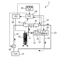
本発明の実施例1に係る燃料噴射システム5について説明する。図1は、燃料噴射システム5の構成を示す模式図である。燃料噴射システム5は、主として、燃料タンク10と、サプライポンプ20と、コモンレール30と、インジェクタ40と、各種通路(供給通路50、高圧燃料通路51、第1リターン通路52、第2リターン通路53および第3リターン通路54)と、圧力調整弁60と、圧力センサ70と、回転数センサ80と、EDU90と、ECU100と、を備える。
A
燃料タンク10は燃料を貯留するためのタンクである。燃料としては、内燃機関用の燃料であれば特に限定されない。本実施例においては、燃料としてディーゼル燃料が用いられる。サプライポンプ20は、ECU100からの指示を受けて駆動し、燃料タンク10の燃料を汲み上げて、供給通路50を介してコモンレール30に供給する。
The
コモンレール30には、レール圧センサ32と減圧弁34とが配置されている。レール圧センサ34は、レール圧を取得し、取得結果をECU100に伝える。減圧弁34は、ECU100から指示を受けたEDU90によって制御されることによって、レール圧を調整する。ECU100は、レール圧センサ32の取得したレール圧が目標圧力よりも高い場合には、レール圧が目標圧力に調整されるようにEDU90に指示を与える。その結果、減圧弁34は、コモンレール30内の燃料を第2リターン通路53にリークさせることによって、レール圧を減少させる。コモンレール30を経由した燃料は、高圧燃料通路51を通過してインジェクタ40に供給される。第2リターン通路53を流動した燃料は、燃料タンク10に戻る。
A
インジェクタ40は、ECU100からの指示を受けたEDU90によって駆動される。インジェクタ40は、コモンレール30から供給された高圧燃料を内燃機関の例えば気筒内に噴射する燃料噴射手段としての機能を有する。本実施例において燃料噴射システム5は、複数のインジェクタ40を有する。なお、インジェクタ40は、高圧燃料の一部をインジェクタ40の駆動に用いる。インジェクタ40の駆動に供された高圧燃料の一部は、第1リターン通路52および第3リターン通路54を流動して燃料タンク10に戻る。インジェクタ40の詳細は、後述する。
The
圧力調整弁60は、ECU100の指示を受けて、第1リターン通路52の圧力を調整する。圧力センサ70は、第1リターン通路52の圧力を取得し、取得結果をECU100に伝える。すなわち、圧力センサ70は、第1リターン通路52を流動する燃料(後述するリターン燃料)の圧力を取得する圧力取得手段として機能する。
The
回転数センサ80は、内燃機関の回転数を取得し、取得結果をECU100に伝える。回転数センサ80は、内燃機関の運転状態に関する情報を取得する運転情報取得手段として機能する。また、ECU100は、燃料噴射量のマップを有している。ECU100は、燃料噴射量に基づいて負荷を把握する。すなわち、ECU100は、内燃機関の運転状態に関する情報(負荷)を取得する運転状態取得手段として機能する。なお、ECU100は、例えばアクセル開度等に基づいて負荷を把握してもよい。
The
EDU90は、ECU100からの指示を受けて、減圧弁34およびインジェクタ40に入力される信号を制御する。それにより、減圧弁34およびインジェクタ40の後述するピエゾスタック231の動作が制御される。
In response to an instruction from the
ECU100は、CPU、ROMおよびRAMを有するマイクロコンピュータである。ECU100は、内燃機関の負荷および内燃機関の回転数に応じて、サプライポンプ20を制御する。それにより、サプライポンプ20の吐出量が調整される。また、ECU100は、内燃機関の負荷および回転数に応じて、EDU90を制御する。それにより、減圧弁34およびインジェクタ40のピエゾスタック231の動作が制御される。さらに、ECU100は、内燃機関の負荷および回転数と、圧力センサ70の取得結果と、に基づいて、圧力調整弁60を制御する。すなわち、本実施例において、圧力調整弁60およびECU100は、運転情報取得手段および圧力取得手段の取得結果に基づいて、第1リターン通路52を流動するリターン燃料の圧力を調整する圧力調整手段として機能する。圧力調整弁60の制御の詳細については後述する。
The ECU 100 is a microcomputer having a CPU, a ROM, and a RAM. The ECU 100 controls the
図2は、インジェクタ40の模式的断面図である。インジェクタ40は主として、ボディ200と、ボディ200内に配置されたニードル220と、ボディ200内に配置されたピエゾ駆動部(ピエゾスタック231、駆動ピストン232、チェックボール233およびスプリング234)と、を備える。
FIG. 2 is a schematic cross-sectional view of the
ボディ200の先端には噴孔201が形成されている。ボディ200の内部には、高圧燃料溜室202と、制御室(第1制御室203および第2制御室204)と、作動燃料室205と、各種通路(第1通路206、第2通路207および第3通路208)と、が形成されている。
A
高圧燃料溜室202は、高圧燃料用入口209に、第1通路206を介して連通している。高圧燃料用入口209は、前述した高圧燃料通路51を介してコモンレール30に連通している。噴孔201が閉の場合、コモンレール30から供給された高圧燃料は、第1通路206を流動して高圧燃料溜室202に蓄積される。噴孔201が開の場合、高圧燃料溜室202の高圧燃料は、噴孔201から噴射される。
The high-
制御室は、ニードル220を閉弁方向に付勢する機能を有する室である。本実施例において、制御室は、第1制御室203と第2制御室204とを有する。第1制御室203は、ニードル220の基端部(ニードル220の先端とは反対側の端部)によって区画された領域である。第1制御室203は、第2通路207を介して第1通路206に連通している。それにより、コモンレール30から供給された高圧燃料は、第1制御室203に流入する。すなわち、第1制御室203は、コモンレール30から供給された高圧燃料をニードル220の基端側に貯留する室である。第2制御室204は、ニードル220の基端部の外周壁によって区画された領域である。第2制御室204には、スプリング211が配置されている。スプリング211は、ニードル220を閉弁方向に付勢している。
The control chamber is a chamber having a function of urging the
なお、ニードル220の基端部の外周壁は、第1制御室203内を摺動する。よって、ニードル220の基端部の外周壁と第1制御室203の内周壁との間には、若干のクリアランスが設けられている。このクリアランスによって、第1制御室203と第2制御室204とは、連通している。それにより、第1制御室203の高圧燃料は、微量ではあるが、第2制御室204に流入する。第1制御室203を経由した燃料をリターン燃料と称する。
Note that the outer peripheral wall of the proximal end portion of the
第2制御室204は、第3通路208を介してリターン燃料用出口210に連通している。なお、リターン燃料用出口210は、第1リターン通路52および第3リターン通路54を介して燃料タンク10に連通している。それにより、第2制御室204のリターン燃料は、第3通路208、第1リターン通路52および第3リターン通路54を流動して、燃料タンク10に戻る。
The
作動燃料室205は、後述する駆動ピストン232に形成された連通路235が連通状態の場合に、第3通路208のリターン燃料を蓄積する。作動燃料室205は、ピエゾ駆動部のピエゾスタック231の初期状態からの伸長変位量に応じて容積が減少する。そして、作動燃料室205は、ニードル220が閉弁方向に付勢されるように、蓄積したリターン燃料をニードル220に導いている。
The working
なお、ニードル220の後述する拡径部は、第2制御室204内を摺動する。よって、ニードル220の拡径部の外周壁と第2制御室204の内周壁との間には、若干のクリアランスが設けられている。このクリアランスによって、作動燃料室205と第2制御室204とは、連通している。そのため、作動燃料室205の燃料は、第2制御室204に流入する。
Note that a diameter-enlarged portion (described later) of the
ニードル220は、その先端が噴孔201を開閉するように、ボディ200内に配置されている。ニードル220は、先端部と基端部との間に拡径した拡径部を有する。拡径部は、第2制御室204内を摺動する。ニードル220は、制御室とスプリング211から受ける閉弁方向への付勢力と、作動燃料室205から受ける開弁方向の付勢力と、の差によって駆動する。それにより、ニードル220の先端部が噴孔201を開閉する。その結果、コモンレール30から供給された高圧燃料の噴射量が調整される。
The
ピエゾ駆動部は、ピエゾスタック231と、駆動ピストン232と、チェックボール233と、スプリング234と、を有する。ピエゾスタック231は、電荷量の増減に応じて伸縮変位する。本実施例においては、ECU100に制御されたEDU90によって、ピエゾスタック231の電荷量が調整される。
The piezo drive unit includes a
駆動ピストン232は、ピエゾスタック231と後述する作動燃料室205との間に配置されている。駆動ピストン232は、ピエゾスタック231の伸縮変位と同期して変位する。駆動ピストン232が作動燃料室205側に変位すると、作動燃料室205の容積が減少する。すなわち、駆動ピストン232は、ピエゾスタックの伸長変位量に応じて作動燃料室205の容積を減少させる。なお、駆動ピストン232には、作動燃料室205と後述する第3通路208とを連通する連通路235が形成されている。
The
チェックボール233は、連通路235の連通状態と遮断状態とを切替える弁部である。本実施例において、チェックボール233は、駆動ピストン232の作動燃料室205側に形成された内部空洞部に配置されている。スプリング234は、駆動ピストン232をピエゾスタック231が収縮する方向に付勢している。
The
インジェクタ40は、以下のように作動する。まず、ピエゾスタック231に電荷が供給される前の状態(以下、初期状態と称する)において、チェックボール233は、連通路235を連通状態にする。その結果、第3通路208のリターン燃料は、作動燃料室205に流入する。この場合、作動燃料室205の圧力は、第3通路208の圧力と等しくなる。一方、コモンレール30からの高圧燃料は、制御室に流入する。ここで、前述したようにニードル220は制御室とスプリング211から受ける付勢力と作動燃料室205から受ける付勢力との差によって駆動する。よって、この場合、作動燃料室205から受ける付勢力より制御室から受ける付勢力の方が強いことから、ニードル220は噴孔201を閉にする。この場合、燃料噴射は行われない。
The
図3は、ピエゾスタック231に電荷が供給された場合のインジェクタ40の模式的断面図である。EDU90がピエゾスタック231に電荷を供給した場合、ピエゾスタック231は伸長変位する。その結果、駆動ピストン232は、作動燃料室205の容積を減少させる。ここで、チェックボール233は、慣性によって、駆動ピストン232に遅れて移動する。その結果、チェックボール233は、連通路235の作動燃料室205側の開口部を閉塞する。それにより、連通路235は遮断状態となる。
FIG. 3 is a schematic cross-sectional view of the
次いで、ピエゾスタック231の電荷量が増大することによってピエゾスタック231がさらに伸長変位した場合、作動燃料室205の内圧は上昇する。その結果、ニードル220に作動燃料室205から作用する付勢力が制御室とスプリング211からニードル220に作用する付勢力より大きくなった場合、ニードル220は開弁方向に変位する。それにより、噴孔201が開になり、燃料噴射が開始される。
Next, when the
また、EDU90がピエゾスタック231の電荷量を減少させた場合、ピエゾスタック231は収縮変位する。この場合、スプリング234からの付勢力によってピエゾスタック231の収縮変位は助長される。ピエゾスタック231が収縮変位した場合、駆動ピストン232は作動燃料室205の容積が増大する方向に変位する。その結果、作動燃料室205の内圧が減少する。作動燃料室205からの付勢力より制御室とスプリング211からの付勢力の方が大きくなった場合、ニードル220は、図2に示すように噴孔201を閉にする。それにより、燃料噴射が停止される。
Further, when the
なお、前述したように、作動燃料室205の燃料は、ニードル220の拡径部の外周壁と第2制御室204の内周壁とのクリアランスを通過して第2制御室204に流入する。それにより、ピエゾスタック231が初期状態に戻った場合、作動燃料室205の燃料量は、当初作動燃料室205に蓄積されていた燃料量より減少する。その結果、ピエゾスタック231が初期状態に戻った場合、作動燃料室205の内圧は第3通路208の内圧より低くなる。それにより、チェックボール233は、連通路235内の内圧によって作動燃料室205側に押される。その結果、連通路235は連通状態となる。以上のように、インジェクタ40は作動する。
As described above, the fuel in the working
ここで、例えば、ピエゾスタック231への電荷の供給速度を変更することによって、ピエゾスタック231の伸長速度を変更することができる。その結果、ニードル220の変位速度を変更することができる。しかし、この場合、EDU90およびECU100の構成が複雑化することから、燃料噴射システム5のコストが上昇するおそれがある。
Here, for example, by changing the charge supply speed to the
そこで、ピエゾスタック231への電荷供給速度を変更することなく、ニードルの変位速度を変更する方法について考察する。ピエゾスタック231の初期状態における作動燃料室205の圧力をPとする。ピエゾスタック231の初期状態における作動燃料室205の容積をVとする。そして、ピエゾスタック231の伸長変位よって作動燃料室205の容積が△V圧縮されたとする。この場合、圧縮後の作動燃料室205の内圧△Pは、下記式(1)によって表される。なお、K(P)は、体積弾性係数である。
△P=K(P)×△V/V・・・(1)
Therefore, a method of changing the needle displacement speed without changing the charge supply speed to the
ΔP = K (P) × ΔV / V (1)
図4は、体積弾性係数(K(P))と作動燃料室205の圧力との関係を示す図である。図4に示すように、K(P)は、圧力と比例関係にある。よって、ピエゾスタック231の初期状態における作動燃料室205の圧力Pが異なると、K(P)の値が異なる。その結果、式(1)から、△Pの値も異なる。△Pの値は、ニードル220の加速度に影響を及ぼす。よって、ピエゾスタック231の初期状態における作動燃料室205の圧力Pを調整することによって、ニードル220の変位速度を変化させることができる。
FIG. 4 is a diagram showing the relationship between the bulk modulus (K (P)) and the pressure in the working
ここで、ピエゾスタック231の初期状態における作動燃料室205の圧力Pは、リターン燃料の圧力と等しい。リターン燃料の圧力は、第1リターン通路52の圧力を調整することによって、調整され得る。
Here, the pressure P of the working
そこで、本実施例においては、第1リターン通路52の圧力を取得する圧力センサ70と、第1リターン通路52の圧力を調整する圧力調整弁60と、圧力調整弁60を制御するECU100と、を備えている。例えば、ECU100は、内燃機関の運転状態に関する情報である内燃機関の負荷および回転数と、圧力センサ70の取得結果と、に基づいて、圧力センサ70の取得結果が所定の値になるように、圧力調整弁60を制御する。
Therefore, in this embodiment, a
具体的には、ECU100は、内燃機関の負荷および回転数に応じて設定された第1リターン通路52内の圧力のマップを記憶しておく。そして、内燃機関の負荷および回転数と、圧力センサ70の取得結果と、に基づいて、圧力センサ70の取得結果がマップに記載された所定の値になるように、圧力調整弁60を制御する。それにより、第1リターン通路52の圧力が変化することから、作動燃料室205の圧力Pを変化させることができる。その結果、ピエゾスタック231への電荷供給速度を変更することなく、ニードル220の変位速度を変更することができる。
Specifically, the
以上本発明の好ましい実施形態について詳述したが、本発明はかかる特定の実施形態に限定されるものではなく、特許請求の範囲に記載された本発明の要旨の範囲内において、種々の変形・変更が可能である。 Although the preferred embodiments of the present invention have been described in detail above, the present invention is not limited to such specific embodiments, and various modifications and changes can be made within the scope of the gist of the present invention described in the claims. It can be changed.
5 燃料噴射システム
30 コモンレール
32 レール圧センサ
34 減圧弁
40 インジェクタ
52 第1リターン通路
60 圧力調整弁
70 圧力センサ
80 回転数センサ
90 EDU
100 ECU
200 ボディ
201 噴孔
202 高圧燃料溜室
203 第1制御室
204 第2制御室
205 作動燃料室
220 ニードル
231 ピエゾスタック
232 駆動ピストン
233 チェックボール
235 連通路
DESCRIPTION OF
100 ECU
200
Claims (2)
前記内燃機関の運転状態に関する情報を取得する運転情報取得手段と、
前記リターン燃料の圧力を取得する圧力取得手段と、
前記運転情報取得手段および前記圧力取得手段の取得結果に基づいて、前記リターン燃料の圧力を調整する圧力調整手段と、を備えることを特徴とする燃料噴射システム。 A control chamber for storing high-pressure fuel supplied from a common rail on the proximal end side of the needle, a piezo drive unit that expands and contracts in accordance with an increase or decrease in the amount of charge, and when the piezo drive unit is in an initial state, passes through the control chamber The return fuel, which is the high-pressure fuel, is accumulated inside, and the internal pressure is increased by decreasing the volume according to the amount of extension displacement from the initial state of the piezo drive unit, and the needle is urged in the valve opening direction. A fuel injection means having an operating fuel chamber for guiding the return fuel whose internal pressure has been increased to the needle,
Driving information acquisition means for acquiring information related to the operating state of the internal combustion engine;
Pressure acquisition means for acquiring the pressure of the return fuel;
A fuel injection system comprising: a pressure adjusting unit that adjusts the pressure of the return fuel based on acquisition results of the operation information acquisition unit and the pressure acquisition unit.
電荷量の増減に応じて伸縮変位するピエゾスタックと、
前記ピエゾスタックと前記作動燃料室との間に配置され、前記ピエゾスタックの前記初期状態からの伸長変位量に応じて前記作動燃料室の容積を減少させるとともに、前記リターン燃料を前記作動燃料室に導く連通路を有する駆動ピストンと、
前記ピエゾスタックが前記初期状態の場合に前記連通路を連通状態とし、前記初期状態以外の場合に前記連通路を遮断状態とする弁部と、を有する請求項1記載の燃料噴射システム。 The piezo drive unit is
Piezo stack that expands and contracts according to increase and decrease of charge amount,
It is arranged between the piezo stack and the working fuel chamber, and reduces the volume of the working fuel chamber according to the amount of extension displacement from the initial state of the piezo stack, and the return fuel to the working fuel chamber. A drive piston having a communicating passage for guiding;
2. The fuel injection system according to claim 1, further comprising: a valve portion that places the communication passage in a communication state when the piezo stack is in the initial state and shuts off the communication passage in a state other than the initial state.
Priority Applications (1)
| Application Number | Priority Date | Filing Date | Title |
|---|---|---|---|
| JP2009090662A JP2010242566A (en) | 2009-04-03 | 2009-04-03 | Fuel injection system |
Applications Claiming Priority (1)
| Application Number | Priority Date | Filing Date | Title |
|---|---|---|---|
| JP2009090662A JP2010242566A (en) | 2009-04-03 | 2009-04-03 | Fuel injection system |
Publications (1)
| Publication Number | Publication Date |
|---|---|
| JP2010242566A true JP2010242566A (en) | 2010-10-28 |
Family
ID=43095845
Family Applications (1)
| Application Number | Title | Priority Date | Filing Date |
|---|---|---|---|
| JP2009090662A Pending JP2010242566A (en) | 2009-04-03 | 2009-04-03 | Fuel injection system |
Country Status (1)
| Country | Link |
|---|---|
| JP (1) | JP2010242566A (en) |
Cited By (2)
| Publication number | Priority date | Publication date | Assignee | Title |
|---|---|---|---|---|
| JP2014015918A (en) * | 2012-07-11 | 2014-01-30 | Denso Corp | Fuel injection system of internal combustion engine |
| KR102937177B1 (en) * | 2020-10-16 | 2026-03-11 | 에이치디한국조선해양 주식회사 | Vessel using ammonia as fuel |
-
2009
- 2009-04-03 JP JP2009090662A patent/JP2010242566A/en active Pending
Cited By (2)
| Publication number | Priority date | Publication date | Assignee | Title |
|---|---|---|---|---|
| JP2014015918A (en) * | 2012-07-11 | 2014-01-30 | Denso Corp | Fuel injection system of internal combustion engine |
| KR102937177B1 (en) * | 2020-10-16 | 2026-03-11 | 에이치디한국조선해양 주식회사 | Vessel using ammonia as fuel |
Similar Documents
| Publication | Publication Date | Title |
|---|---|---|
| JP3707210B2 (en) | Fuel injection control device | |
| JP4855946B2 (en) | Fuel injection valve | |
| US8342424B2 (en) | Fuel injection apparatus | |
| EP1803917B1 (en) | Control method of a common-rail type system for direct fuel injection into an internal combustion engine | |
| JP2010242566A (en) | Fuel injection system | |
| CA3002559A1 (en) | Internal combustion engine with injection quantity control | |
| JP4182922B2 (en) | Exhaust valve drive control method and apparatus | |
| JP2008002306A (en) | Fuel injection valve | |
| JP4552834B2 (en) | Fuel injection device | |
| JP4618257B2 (en) | Fuel injection valve | |
| JP4550991B2 (en) | Fuel / water injection internal combustion engine | |
| JPH10274130A (en) | Accumulator fuel injection device | |
| WO2006033469A1 (en) | Fuel injection device | |
| JP4552991B2 (en) | Fuel injection control system and fuel injection valve | |
| JP4635980B2 (en) | Fuel supply system | |
| JP4404056B2 (en) | Fuel injection device for internal combustion engine | |
| JP5260222B2 (en) | Accumulated fuel injection system | |
| JP2008163806A (en) | Fuel pressure storage device and fuel injection device | |
| JP4329761B2 (en) | Fuel injection device | |
| JP2009019565A (en) | Fuel injection device | |
| JP4591436B2 (en) | Fuel injection device | |
| JP2008151077A (en) | Fuel injection device | |
| JP2010236494A (en) | Fuel injection valve and fuel injection device | |
| JP2005248853A (en) | Injector | |
| JP2005155537A (en) | Booster fuel injection system |