JP2010246794A - X-ray imaging device - Google Patents
X-ray imaging device Download PDFInfo
- Publication number
- JP2010246794A JP2010246794A JP2009100742A JP2009100742A JP2010246794A JP 2010246794 A JP2010246794 A JP 2010246794A JP 2009100742 A JP2009100742 A JP 2009100742A JP 2009100742 A JP2009100742 A JP 2009100742A JP 2010246794 A JP2010246794 A JP 2010246794A
- Authority
- JP
- Japan
- Prior art keywords
- ray
- unit
- light receiving
- receiving area
- area
- Prior art date
- Legal status (The legal status is an assumption and is not a legal conclusion. Google has not performed a legal analysis and makes no representation as to the accuracy of the status listed.)
- Granted
Links
Images



Landscapes
- Apparatus For Radiation Diagnosis (AREA)
Abstract
【課題】被検体の撮影又は透視を行う最中に、オペレータを介在することなく、変更するX線の照射面積に応じて、最適なX線条件に設定可能とすること。
【解決手段】X線Bを照射するX線照射手段1と、X線照射手段1のX線条件を設定するX線設定手段51と、被検体Mを透過するX線の画像を取得する画像取得手段7と、被検体Mを透過するX線の受光エリアを計測する受光エリア計測手段56と、被検体Mを透過するX線の透過光量を計測する光量計測手段57と、受光エリアを変更する受光エリア変更手段80,81と、受光エリア及び透過光量から単位エリア透過光量を算出する算出手段58と、予め設定した単位エリア最適量を記憶する記憶手段59と、X線設定手段51を制御する制御手段52とを備え、制御手段52は、受光エリアの変位に応じて、単位エリア透過光量が単位エリア最適量内になるようX線条件を設定する。
【選択図】図1An object of the present invention is to set an optimum X-ray condition in accordance with an irradiation area of X-rays to be changed without intervention of an operator during imaging or fluoroscopy of a subject.
An X-ray irradiating means for irradiating X-rays B, an X-ray setting means for setting X-ray conditions of the X-ray irradiating means, and an image for acquiring an X-ray image transmitted through a subject. The acquisition unit 7, the light receiving area measuring unit 56 that measures the X-ray light receiving area that passes through the subject M, the light amount measuring unit 57 that measures the transmitted light amount of the X-ray that passes through the subject M, and the light receiving area are changed. Control the light receiving area changing means 80 and 81, the calculating means 58 for calculating the unit area transmitted light amount from the light receiving area and the transmitted light amount, the storage means 59 for storing the preset unit area optimum amount, and the X-ray setting means 51. The control means 52 sets the X-ray condition so that the unit area transmitted light amount is within the optimum unit area amount in accordance with the displacement of the light receiving area.
[Selection] Figure 1
Description
本発明は、X線照射手段から被検体にX線を照射して、被検体のX線画像を取得するX線画像装置に関する。 The present invention relates to an X-ray image apparatus that acquires an X-ray image of a subject by irradiating the subject with X-rays from an X-ray irradiation means.
X線画像装置は、X線照射手段から被検体にX線を照射して、被検体のX線画像を取得する装置である。X線画像装置は、被検体にX線を照射して撮影を行う前に、オペレータが、照射するX線線量が大きいか小さいかを判断して、X線管電圧等のX線条件を入力設定する。この入力設定に基づいて高電圧発生部を操作して、X線照射手段の制御を行う(例えば、特許文献1)。このように、撮影前に、オペレータがX線条件を設定することで、最適な線量のX線を被検体に照射する。 The X-ray imaging apparatus is an apparatus that acquires an X-ray image of a subject by irradiating the subject with X-rays from an X-ray irradiation unit. The X-ray imaging device determines whether the X-ray dose to be irradiated is large or small, and inputs X-ray conditions such as the X-ray tube voltage before irradiating the subject with X-rays. Set. Based on this input setting, the high voltage generator is operated to control the X-ray irradiation means (for example, Patent Document 1). As described above, the operator sets the X-ray condition before the imaging, so that the subject is irradiated with the X-ray having the optimum dose.
ところで、X線画像装置で撮影又は透視を行う最中に、被検体の所定部位にX線が照射されないように、照射するX線の照射面積を変更することがある。そして、オペレータは、照射面積の変更に応じて、撮影前に設定したX線条件を変更して、最適なX線線量になるように再度入力設定を行う。即ち、照射面積を小さくした場合は、それに応じてX線線量を小さくし、照射面積を大きくした場合は、X線線量を大きくする。従って、撮影中に照射面積を変更する度に、オペレータはX線条件を再度入力設定する手間を要し、また、入力ミスにより不適切な線量のX線を被検体に照射することがあった。 By the way, during imaging or fluoroscopy with an X-ray imaging apparatus, the irradiation area of X-rays to be irradiated may be changed so that X-rays are not irradiated to a predetermined part of the subject. Then, the operator changes the X-ray condition set before imaging in accordance with the change of the irradiation area, and performs input setting again so as to obtain an optimal X-ray dose. That is, when the irradiation area is reduced, the X-ray dose is reduced accordingly, and when the irradiation area is increased, the X-ray dose is increased. Therefore, every time the irradiation area is changed during imaging, the operator needs to input and set the X-ray conditions again, and the subject may be irradiated with an inappropriate dose of X-rays due to an input error. .
そこで、本発明が解決しようとする課題は、上記した問題に鑑みて、被検体の撮影又は透視を行う最中に、オペレータを介在することなく、変更するX線の照射面積に応じて、最適なX線条件に設定可能なX線画像装置を提供することにある。 Therefore, in view of the above problems, the problem to be solved by the present invention is optimal in accordance with the X-ray irradiation area to be changed without intervention of an operator during imaging or fluoroscopy of the subject. Another object of the present invention is to provide an X-ray image apparatus that can be set to various X-ray conditions.
上記課題を解決するために、本発明に係るX線画像装置は、
X線を照射するX線照射手段と、X線照射手段のX線条件を設定するX線設定手段と、被検体を透過するX線の画像を取得する画像取得手段と、被検体を透過するX線の受光エリアを計測する受光エリア計測手段と、被検体を透過するX線の透過光量を計測する光量計測手段と、受光エリアを変更する受光エリア変更手段と、受光エリア及び透過光量から単位エリア透過光量を算出する算出手段と、予め設定した単位エリア最適量を記憶する記憶手段と、X線設定手段を制御する制御手段とを備え、
制御手段は、受光エリアの変位に応じて、単位エリア透過光量が単位エリア最適量内になるようX線条件を設定する。
In order to solve the above problems, an X-ray imaging apparatus according to the present invention provides:
X-ray irradiation means for irradiating X-rays, X-ray setting means for setting X-ray conditions of the X-ray irradiation means, image acquisition means for acquiring an X-ray image that passes through the subject, and transmission through the subject Light receiving area measuring means for measuring the X-ray light receiving area, light quantity measuring means for measuring the transmitted light quantity of the X-ray transmitted through the subject, light receiving area changing means for changing the light receiving area, and the unit from the light receiving area and the transmitted light quantity A calculation means for calculating the area transmitted light amount, a storage means for storing a preset unit area optimum amount, and a control means for controlling the X-ray setting means,
The control means sets the X-ray condition so that the unit area transmitted light amount is within the unit area optimum amount according to the displacement of the light receiving area.
好ましくは、受光エリア変更手段は、X線照射手段から照射するX線の照射角度を変更する照射角度変更手段と、X線照射手段から照射するX線の照射野を変更するコリメータとを備え、
受光エリア計測手段は、照射角度及びコリメータの開き量に基づいて受光エリアを算出する。
Preferably, the light receiving area changing means includes an irradiation angle changing means for changing an X-ray irradiation angle irradiated from the X-ray irradiation means, and a collimator for changing an X-ray irradiation field irradiated from the X-ray irradiation means,
The light receiving area measuring means calculates the light receiving area based on the irradiation angle and the opening amount of the collimator.
好ましくは、X線照射手段は、X線を被検体に間欠的に照射して撮影する撮影モードと、X線を被検体に連続的に照射して透視する透視モードとを備え、
単位エリア最適量は、撮影モード及び透視モードのそれぞれについて設定される。
Preferably, the X-ray irradiation means includes an imaging mode in which X-rays are intermittently irradiated onto the subject and imaged, and a fluoroscopy mode in which the X-rays are continuously irradiated on the subject to perform fluoroscopy.
The unit area optimum amount is set for each of the photographing mode and the fluoroscopic mode.
本発明に係るX線画像装置は、上記の通り、被検体を透過するX線の透過光量を計測する光量計測手段と、受光エリアを計測する受光エリア計測手段と、透過光量及び受光エリアから単位エリア透過光量を算出する算出手段と、予め設定した単位エリア最適量を記憶する記憶手段と、X線設定手段を制御する制御手段とを備える。そして、制御手段は、受光エリアの変位に応じて、単位エリア透過光量が単位エリア最適量内になるようにX線条件を設定する。 As described above, the X-ray imaging apparatus according to the present invention includes a light amount measuring unit that measures the transmitted light amount of X-rays that pass through the subject, a light receiving area measuring unit that measures the light receiving area, and a unit from the transmitted light amount and the light receiving area. Calculation means for calculating the area transmitted light amount, storage means for storing a preset unit area optimum amount, and control means for controlling the X-ray setting means. Then, the control unit sets the X-ray condition so that the unit area transmitted light amount is within the unit area optimum amount according to the displacement of the light receiving area.
従って、X線撮影又は透視を行う最中に、被検体の所定部位にX線が照射されないように、オペレータが被検体に照射するX線の受光エリアを変更しても、制御手段が、受光エリアの変位に応じて、単位エリア透過光量が単位エリア最適量内になるようにX線条件を設定するので、オペレータはX線条件を再度入力設定する手間がなく、また、オペレータの入力ミスにより不適切な線量のX線を被検体に照射することもない。 Therefore, during the X-ray imaging or fluoroscopy, even if the operator changes the X-ray light receiving area irradiated to the subject so that the predetermined part of the subject is not irradiated with X-rays, the control means Since the X-ray conditions are set so that the unit area transmitted light amount is within the optimal unit area according to the displacement of the area, there is no need for the operator to input and set the X-ray conditions again. The subject is not irradiated with an inappropriate dose of X-rays.
以下、添付図面に基づいて、本発明に係るX線画像装置の実施形態について説明する。 Embodiments of an X-ray imaging apparatus according to the present invention will be described below with reference to the accompanying drawings.
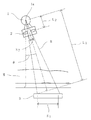
図1は、X線画像装置を示すブロック図である。図2及び図3は、受光エリアの計測方法を説明するための図である。図4は、X線画像装置の制御方法を説明するためのフローチャート図である。 FIG. 1 is a block diagram showing an X-ray imaging apparatus. 2 and 3 are diagrams for explaining a method of measuring the light receiving area. FIG. 4 is a flowchart for explaining a control method of the X-ray imaging apparatus.
図1の通り、X線画像装置は、X線透過材料で形成された天板4を備える。天板4に、被検体(例えば患者)Mが載せられる。X線画像装置は、被検体MにX線Bを照射するX線管(X線照射手段)1を備える。X線管1は、照射されるX線の一部を遮蔽して、照射野を規定するコリメータ2を備える。X線画像装置は、被検体Mを透過するX線を検出するX線検出器3を備える。X線検出器3は、例えば、FPD(フラットパネル型X線検出器)からなる。
As shown in FIG. 1, the X-ray imaging apparatus includes a top plate 4 formed of an X-ray transmissive material. A subject (for example, a patient) M is placed on the top 4. The X-ray imaging apparatus includes an X-ray tube (X-ray irradiation means) 1 that irradiates a subject M with X-rays B. The
X線画像装置は、管電圧発生装置5を備える。管電圧発生装置5は、X線管1に管電圧V及び管電流Iを与える管電圧発生部50と、管電圧発生部50が与えるX線条件(管電圧V、管電流I等)を設定するX線設定部51と、を備える。X線画像装置は、画像取得部7を備える。画像取得部7は、X線検出器3で検出した透過X線の検出信号を読み取る画像読取部70と、画像読取部70からの読取データを処理して画像データを生成する画像処理部71と、画像処理部71からの画像データを格納する画像メモリ72と、画像メモリ72に接続され、X線画像を表示するモニタ72とを備える。
The X-ray imaging apparatus includes a tube voltage generator 5. The tube voltage generator 5 sets a
X線画像装置は、X線管1を角度回転して、X線Bの照射角度を変更する照射角度変更部80を備える。照射角度変更部80は、例えば、X線管1に出力軸が連結されたパルスモーターからなる。X線画像装置は、コリメータ2を駆動して、X線の照射野を変更するコリメータ駆動部81を備える。コリメータ駆動部81は、例えば、コリメータ2を縦軸及び横軸にスライド移動するレール及びモーター等のスライド機構を備える。
The X-ray imaging apparatus includes an irradiation
X線画像装置は、照射角度変更部80及びコリメータ駆動部81の駆動を操作するための操作部8を備える。オペレータは、モニタ73に表示されたX線画像を観察しながら、操作部8で照射角度変更部80及びコリメータ駆動部81を操作して、被検体Mの所定部位にX線Bが照射されないように、被検体Mに照射されるX線Bの位置を移動したり、被検体Mに照射されるX線Bの照射野を変更する。従って、照射角度変更部80及びコリメータ駆動部81は、被検体Mを透過するX線Bの受光エリア(受光面積)を変更できる(受光エリア変更手段)。
The X-ray imaging apparatus includes an operation unit 8 for operating driving of the irradiation
高電圧発生装置5は、X線設定部51を制御して、照射するX線BのX線条件を変更設定する制御部52を備える。高電圧発生装置5は、X線管1からのX線Bの照射角度θを計測する照射角度計測部53と、コリメータ2の開き量S2を計測する照射野計測部54と、X線管1とX線検出器3との距離L1を計測する照射距離計測部55とを備える。照射角度計測部53は、例えば、照射角度変更部80のパルスモーター等に接続された角度センサーからなる。照射野計測部54は、例えば、コリメータ駆動部81のスライド機構に接続された水平位置センサーに基づいて計測する。また、照射距離計測部55は、例えば、X線管1及びX線検出器3に接続された昇降位置センサーに基づいて計測する。
The high voltage generator 5 includes a
高電圧発生装置5は、被検体Mを透過するX線Bの受光エリア(受光面積)S1を計測する受光エリア計測部56を備える。受光エリア計測部56は、照射距離計測部55で求めた距離L1、X線管1のX線焦点1aとコリメータ2との距離L2、照射野計測部54で求めた開き量S2、照射角度計測部53で求めた照射角度θに基づいて、受光エリアS1を算出する。
High-voltage generator 5 includes a light receiving
図2及び図3の通り、受光エリアS1は、距離L1、距離L2、開き量S2、照射角度θに基づいて、下記(1)式より算出する。図2はθ=0の場合を示す。
・ S1=((L1/L2)2×S2)/cosθ ・・・(1)
なお、上記(1)式は、算出速度を高速化するために近似化した式であるが、詳細に求めた式でも良い。
As Figures 2 and 3, the light receiving area S 1, the distance L 1, the distance L 2, the opening amount S 2, based on the irradiation angle theta, is calculated from the following equation (1). FIG. 2 shows the case where θ = 0.
S 1 = ((L 1 / L 2 ) 2 × S 2 ) / cos θ (1)
In addition, although said (1) Formula is a formula approximated in order to speed up calculation speed, the formula calculated | required in detail may be sufficient.
高電圧発生装置5は、被検体Mを透過するX線Bの透過光量Pを計測する光量計測部57を備える。光量計測部57は、例えば、X線検出器3から取得される画素値に基づいて透過光量Pを計測する。従って、光量計測部57は、被検体Mの体厚に応じて変位する透過光量Pを実測することになる。透過光量Pは、X線CT装置ではCT値に基づいて計測することができる。
The high voltage generator 5 includes a light
高電圧発生装置5は、受光エリア計測部56で計測した受光エリアS1、光量計測部57で計測した透過光量Pに基づいて、単位エリア透過光量Amを算出する算出部58を備える。単位エリア透過光量Amは、単位エリア当たりの透過光量であり、下記(2)式より算出する。単位エリア透過光量Amは、オペレータが操作部8を操作して変更する受光エリアS1に応じて変位するので、例えば所定時間単位Δt毎にその都度算出する。
・ Am=P/S1 ・・・(2)
High-voltage generator 5 includes a calculating
A m = P / S 1 (2)
高電圧発生装置5は、予め設定した単位エリア最適量Abを記憶する記憶部59を備える。単位エリア最適量Abは、単位エリア当たりに対する被検体Mを透過するX線の最適な透過光量Pである。単位エリア最適量Abは、一義的な値でなく、所定許容範囲を有した値とすることができる。そして、単位エリア最適量Abは、X線を被検体に間欠的に照射して撮影する撮影モードと、X線を被検体に連続的に照射して透視する透視モードとによって、それぞれ異なる値が設定されている。撮影モードと透視モードとは、被検体Mに対するX線照射時間(撮影時間)が異なるから、その照射時間を考慮して、単位エリア最適量Abを設定できる。従って、撮影モード及び透視モードによって、それぞれの単位エリア最適量Abが選択される。
High-voltage generator 5 includes a
高電圧発生装置5は、算出部58及び記憶部59に接続された比較部60を備える。比較部60は、算出部58で求めた単位エリア透過光量Amと、記憶部59からの単位エリア最適量Abとが入力される。そして、比較部60は、計測した単位エリア透過光量Amと単位エリア最適量Abとを比較して、下記(3)式のように、例えば所定時間単位Δt毎に光量差Acを算出する。
・ Ac=Am−Ab ・・・(3)
The high voltage generator 5 includes a
A c = A m −A b (3)
比較部60は、照射するX線のX線条件を変更設定する制御部52に接続されている。そして、制御部52は、光量差Acが0になるように、X線条件を所定時間単位Δt毎に変更設定して、単位エリア透過光量Amを調整する。例えば、単位エリア最適量Abが画素値600と設定されたとき、計測する単位エリア透過光量Amが画素値600になるように、X線条件を変更設定する。これにより、受光エリアS1が変位する度に、オペレータを介することなく自動的に、単位受光エリアに対する被検体Mを透過するX線線量を最適なものにすることができる。
The
続いて、図4に基づいて、一連のX線撮影方法について説明する。
先ず、オペレータは、記憶部59に単位エリア最適量Abを記憶する(ステップS1)。上記の通り、単位エリア最適量Abは、撮影モードと透視モードとのそれぞれ異なる値を設定できる。そして、オペレータは、操作部8を操作して、照射角度変更部80及びコリメータ駆動部81を駆動することにより、被検体Mの所定部位にX線が照射されないようにする(ステップS2)。照射角度変更部80及びコリメータ駆動部81の駆動に伴って、受光エリア計測部56は、上記(1)式に基づいて、受光エリアS1を計測する(ステップS3)。さらに、光量計測部57は、被検体Mを透過するX線Bの透過光量Pを計測する(ステップS4)。
Next, a series of X-ray imaging methods will be described with reference to FIG.
First, the operator stores the unit area optimal amount A b in the storage unit 59 (step S1). As described above, the unit area optimal amount A b can be set different values between the shooting mode and the fluoroscopic mode. Then, the operator operates the operation unit 8 to drive the irradiation
受光エリア計測部56で求めた受光エリアS1と、光量計測部57で求めた透過光量Pとに基づいて、算出部58は、上記(2)式より、単位エリア透過光量Amを算出する(ステップS5)。そして、算出部58で求めた単位エリア透過光量Amと、記憶部59に記憶した単位エリア最適量Abとに基づいて、比較部60は、上記(3)式のように、単位エリア透過光量Amと単位エリア最適量Abとの光量差Acを算出する(ステップS6)。そして、制御部52は、光量差Acが0になるように、X線設定部51のX線条件を変更設定する(ステップS7)。そして、上記ステップS2〜S7を所定単位時間Δt毎に繰り返し行うことにより、オペレータが照射角度変更部80及びコリメータ駆動部81を駆動して、受光エリアS1を変更する度に、オペレータを介在することなく自動的に、最適なX線条件のX線を被検体へ照射できるので、オペレータによるX線条件の再入力設定を不要とし、入力ミスによる不適切な線量のX線を被検体に照射することがない。
A light receiving area S 1 obtained by the light receiving
さらに、本発明に係るX線画像装置は、フィルム式のX線撮影装置に対しても適用できる。その場合、X線検出器3は、被写体Mを撮影するX線フィルムと、X線を検出するエリアセンサーとを備える。そして、エリアセンサーが、光量計測部57に接続されており、被検体Mを透過するX線の透過光量Pを計測するよう構成される。
Furthermore, the X-ray image apparatus according to the present invention can be applied to a film-type X-ray imaging apparatus. In that case, the
1 X線管(X線照射手段)
2 コリメータ
3 X線検出器
5 高電圧発生装置
7 画像取得部
51 X線設定部
52 制御部
56 受光エリア計測部
57 光量計測部
58 算出部
59 記憶部
80 照射角度変更部
81 コリメータ駆動部
1 X-ray tube (X-ray irradiation means)
2
Claims (3)
前記制御手段は、前記受光エリアの変位に応じて、前記単位エリア透過光量が前記単位エリア最適量内になるよう前記X線条件を設定することを特徴とするX線画像装置。 X-ray irradiation means for irradiating X-rays, X-ray setting means for setting X-ray conditions of the X-ray irradiation means, image acquisition means for acquiring an X-ray image that passes through the subject, and transmission through the subject A light receiving area measuring means for measuring a light receiving area of the X-ray, a light quantity measuring means for measuring a transmitted light quantity of the X-ray transmitted through the subject, a light receiving area changing means for changing the light receiving area, the light receiving area and the light receiving area A calculating means for calculating the unit area transmitted light amount from the transmitted light amount, a storage means for storing a preset unit area optimum amount, and a control means for controlling the X-ray setting means,
The X-ray imaging apparatus characterized in that the control means sets the X-ray condition so that the unit area transmitted light amount is within the unit area optimum amount according to the displacement of the light receiving area.
前記受光エリア計測手段は、前記照射角度及び前記コリメータの開き量に基づいて前記受光エリアを算出することを特徴とする請求項1に記載のX線画像装置。 The light receiving area changing means includes an irradiation angle changing means for changing an X-ray irradiation angle irradiated from the X-ray irradiation means, and a collimator for changing an X-ray irradiation field irradiated from the X-ray irradiation means,
The X-ray imaging apparatus according to claim 1, wherein the light receiving area measuring unit calculates the light receiving area based on the irradiation angle and an opening amount of the collimator.
前記単位エリア最適量は、前記撮影モード及び前記透視モードのそれぞれについて設定されることを特徴とする請求項1又は2のいずれかに記載のX線画像装置。 The X-ray irradiating means includes an imaging mode in which X-rays are intermittently irradiated and imaged, and a fluoroscopic mode in which X-rays are continuously irradiated to the subject and seen through.
The X-ray imaging apparatus according to claim 1, wherein the optimal unit area amount is set for each of the imaging mode and the fluoroscopy mode.
Priority Applications (1)
| Application Number | Priority Date | Filing Date | Title |
|---|---|---|---|
| JP2009100742A JP5625258B2 (en) | 2009-04-17 | 2009-04-17 | X-ray imaging device |
Applications Claiming Priority (1)
| Application Number | Priority Date | Filing Date | Title |
|---|---|---|---|
| JP2009100742A JP5625258B2 (en) | 2009-04-17 | 2009-04-17 | X-ray imaging device |
Publications (2)
| Publication Number | Publication Date |
|---|---|
| JP2010246794A true JP2010246794A (en) | 2010-11-04 |
| JP5625258B2 JP5625258B2 (en) | 2014-11-19 |
Family
ID=43309846
Family Applications (1)
| Application Number | Title | Priority Date | Filing Date |
|---|---|---|---|
| JP2009100742A Expired - Fee Related JP5625258B2 (en) | 2009-04-17 | 2009-04-17 | X-ray imaging device |
Country Status (1)
| Country | Link |
|---|---|
| JP (1) | JP5625258B2 (en) |
Cited By (1)
| Publication number | Priority date | Publication date | Assignee | Title |
|---|---|---|---|---|
| WO2013115389A1 (en) * | 2012-02-01 | 2013-08-08 | 株式会社東芝 | Medical image diagnostic device |
Citations (8)
| Publication number | Priority date | Publication date | Assignee | Title |
|---|---|---|---|---|
| JPH04279153A (en) * | 1991-03-07 | 1992-10-05 | Hitachi Medical Corp | Automatic control mechanism of x-ray conditions |
| JPH06277204A (en) * | 1993-03-25 | 1994-10-04 | Hitachi Medical Corp | X-ray system |
| JPH08299316A (en) * | 1995-04-28 | 1996-11-19 | Toshiba Corp | X-ray diagnostic device |
| JP2003115399A (en) * | 2001-10-02 | 2003-04-18 | Toshiba Corp | X-ray diagnostic equipment |
| JP2003203797A (en) * | 2002-01-09 | 2003-07-18 | Rumio Yuki | X-ray high-voltage apparatus and X-ray imaging apparatus having the same |
| JP2003230555A (en) * | 2002-02-07 | 2003-08-19 | Toshiba Corp | X-ray fluoroscopy diagnostic device |
| JP2004362876A (en) * | 2003-06-03 | 2004-12-24 | Toshiba Corp | X-ray fluoroscope |
| JP2005198762A (en) * | 2004-01-14 | 2005-07-28 | Toshiba Corp | X-ray diagnostic apparatus and irradiation dose control method |
-
2009
- 2009-04-17 JP JP2009100742A patent/JP5625258B2/en not_active Expired - Fee Related
Patent Citations (8)
| Publication number | Priority date | Publication date | Assignee | Title |
|---|---|---|---|---|
| JPH04279153A (en) * | 1991-03-07 | 1992-10-05 | Hitachi Medical Corp | Automatic control mechanism of x-ray conditions |
| JPH06277204A (en) * | 1993-03-25 | 1994-10-04 | Hitachi Medical Corp | X-ray system |
| JPH08299316A (en) * | 1995-04-28 | 1996-11-19 | Toshiba Corp | X-ray diagnostic device |
| JP2003115399A (en) * | 2001-10-02 | 2003-04-18 | Toshiba Corp | X-ray diagnostic equipment |
| JP2003203797A (en) * | 2002-01-09 | 2003-07-18 | Rumio Yuki | X-ray high-voltage apparatus and X-ray imaging apparatus having the same |
| JP2003230555A (en) * | 2002-02-07 | 2003-08-19 | Toshiba Corp | X-ray fluoroscopy diagnostic device |
| JP2004362876A (en) * | 2003-06-03 | 2004-12-24 | Toshiba Corp | X-ray fluoroscope |
| JP2005198762A (en) * | 2004-01-14 | 2005-07-28 | Toshiba Corp | X-ray diagnostic apparatus and irradiation dose control method |
Cited By (4)
| Publication number | Priority date | Publication date | Assignee | Title |
|---|---|---|---|---|
| WO2013115389A1 (en) * | 2012-02-01 | 2013-08-08 | 株式会社東芝 | Medical image diagnostic device |
| JP2013176551A (en) * | 2012-02-01 | 2013-09-09 | Toshiba Corp | Medical image diagnostic apparatus |
| US20140341350A1 (en) * | 2012-02-01 | 2014-11-20 | Kabushiki Kaisha Toshiba | Medical diagnostic imaging apparatus |
| US9980690B2 (en) | 2012-02-01 | 2018-05-29 | Toshiba Medical Systems Corporation | Medical diagnostic imaging apparatus |
Also Published As
| Publication number | Publication date |
|---|---|
| JP5625258B2 (en) | 2014-11-19 |
Similar Documents
| Publication | Publication Date | Title |
|---|---|---|
| JP5333164B2 (en) | Radiography equipment | |
| FI128648B (en) | Computed tomography equipment and imaging control procedure therefor | |
| JP5371758B2 (en) | X-ray CT system | |
| JP6027687B2 (en) | Breast thickness measuring apparatus and breast thickness measuring method | |
| CN102138803A (en) | Radiation imaging system and assist apparatus for the same | |
| JP2009240681A (en) | X-ray radiographic apparatus and method | |
| JP5279672B2 (en) | Radiation imaging system and imaging control method thereof | |
| JP5447526B2 (en) | Radiation imaging apparatus and image acquisition method | |
| CN104010573A (en) | X-ray diagnostic apparatus and method for controlling the same | |
| JP5451099B2 (en) | Radiation imaging system and method of detecting amount of displacement from focal position of radiation source | |
| JP5743731B2 (en) | Radiation imaging apparatus and method | |
| JP2015188611A (en) | Digital panoramic X-ray imaging apparatus and dental CT apparatus | |
| JP5625258B2 (en) | X-ray imaging device | |
| JP5985970B2 (en) | Radiation tomography apparatus and program | |
| CN103315759A (en) | X-ray CT apparatus and method for controlling the same | |
| JP2012148028A (en) | X-ray ct apparatus | |
| JP2009233159A (en) | Radiological diagnostic apparatus | |
| JP4311228B2 (en) | X-ray equipment | |
| JP5855251B2 (en) | Column height sensing for extraoral imaging | |
| JP2009000209A (en) | Method of controlling medical diagnostic imaging apparatus and cradle driving device | |
| JP2008023039A (en) | X-ray ct system | |
| JP2007044134A (en) | X-ray diagnostic equipment | |
| JP2016106814A (en) | Medical image diagnostic apparatus and imaging range display method | |
| JP2006158845A (en) | Radiographing system | |
| JPWO2012050148A1 (en) | X-ray fluoroscopic imaging apparatus and X-ray fluoroscopic imaging method |
Legal Events
| Date | Code | Title | Description |
|---|---|---|---|
| A621 | Written request for application examination |
Free format text: JAPANESE INTERMEDIATE CODE: A621 Effective date: 20110621 |
|
| A977 | Report on retrieval |
Free format text: JAPANESE INTERMEDIATE CODE: A971007 Effective date: 20130110 |
|
| A131 | Notification of reasons for refusal |
Free format text: JAPANESE INTERMEDIATE CODE: A131 Effective date: 20130313 |
|
| A131 | Notification of reasons for refusal |
Free format text: JAPANESE INTERMEDIATE CODE: A131 Effective date: 20140122 |
|
| A521 | Request for written amendment filed |
Free format text: JAPANESE INTERMEDIATE CODE: A523 Effective date: 20140320 |
|
| A521 | Request for written amendment filed |
Free format text: JAPANESE INTERMEDIATE CODE: A821 Effective date: 20140328 |
|
| RD02 | Notification of acceptance of power of attorney |
Free format text: JAPANESE INTERMEDIATE CODE: A7422 Effective date: 20140328 |
|
| RD04 | Notification of resignation of power of attorney |
Free format text: JAPANESE INTERMEDIATE CODE: A7424 Effective date: 20140804 |
|
| TRDD | Decision of grant or rejection written | ||
| A01 | Written decision to grant a patent or to grant a registration (utility model) |
Free format text: JAPANESE INTERMEDIATE CODE: A01 Effective date: 20140902 |
|
| A61 | First payment of annual fees (during grant procedure) |
Free format text: JAPANESE INTERMEDIATE CODE: A61 Effective date: 20140915 |
|
| R151 | Written notification of patent or utility model registration |
Ref document number: 5625258 Country of ref document: JP Free format text: JAPANESE INTERMEDIATE CODE: R151 |
|
| LAPS | Cancellation because of no payment of annual fees |