JP2010257548A - Optical disk device - Google Patents
Optical disk device Download PDFInfo
- Publication number
- JP2010257548A JP2010257548A JP2009109200A JP2009109200A JP2010257548A JP 2010257548 A JP2010257548 A JP 2010257548A JP 2009109200 A JP2009109200 A JP 2009109200A JP 2009109200 A JP2009109200 A JP 2009109200A JP 2010257548 A JP2010257548 A JP 2010257548A
- Authority
- JP
- Japan
- Prior art keywords
- signal
- recording
- focus
- state
- reproduction
- Prior art date
- Legal status (The legal status is an assumption and is not a legal conclusion. Google has not performed a legal analysis and makes no representation as to the accuracy of the status listed.)
- Pending
Links
Images





Landscapes
- Optical Recording Or Reproduction (AREA)
- Optical Head (AREA)
Abstract
【課題】フォーカス制御目標位置を変更する際の再生特性劣化を抑制することができる光ディスク装置を提供する。
【解決手段】情報担体に対して記録再生を行う動作に応じて再生状態、記録前状態、記録中状態の3状態におけるフォーカス制御目標位置を保持し、切替タイミング生成手段からの信号に応じてフォーカス制御目標位置を変更する信号をフォーカス誤差検出手段へ出力するフォーカス位置変更手段とを備え、フォーカス位置変更手段はレンズ位置検出手段からの集光レンズの変動量に応じて記録前におけるフォーカス制御目標位置を変更する。
【選択図】図1An optical disc apparatus capable of suppressing deterioration in reproduction characteristics when a focus control target position is changed is provided.
A focus control target position in three states of a reproduction state, a pre-recording state, and a recording state is held in accordance with an operation for performing recording / reproduction with respect to an information carrier, and focus is determined in accordance with a signal from a switching timing generation unit. A focus position changing means for outputting a signal for changing the control target position to the focus error detecting means, and the focus position changing means is a focus control target position before recording according to the fluctuation amount of the condenser lens from the lens position detecting means. To change.
[Selection] Figure 1
Description
本発明は、記録を行うことのできる円盤状の情報担体(以下光ディスクと呼ぶ)に記録あるいは再生を行う際に、記録前にフォーカス制御目標位置を変更する光ディスク装置に関するものである。 The present invention relates to an optical disc apparatus that changes a focus control target position before recording when recording or reproducing is performed on a disc-shaped information carrier (hereinafter referred to as an optical disc) capable of recording.
従来の光ディスク装置では、信号を再生する場合、比較的弱い一定の光量の光ビームを情報担体である光ディスク1の上に照射し、光ディスク1によって強弱に変調された反射光を検出して行う。また、信号の記録は記録する信号に応じて光ビ−ムの光量を強弱に変調して光ディスク1の上の記録材料膜に情報を書き込む。再生専用の光ディスク1は、ピットによる情報があらかじめスパイラル状に記録されている。また、記録および再生可能である光ディスク1は、スパイラル状の凹凸構造のトラックを有する基材表面に、光学的に記録、再生可能な材料膜を蒸着等の手法で形成して作製される。光ディスク1に情報を記録する、または記録された情報を再生するために、光ビームが記録材料膜上で常に所定の収束状態となるように光ディスク1の面の法線方向(以下フォーカス方向と呼ぶ)に制御するフォーカス制御および光ビームが常に所定のトラック上に位置するように光ディスク1の半径方向(以下トラッキング方向と呼ぶ)に制御するトラッキング制御が必要となる。 In a conventional optical disk apparatus, when reproducing a signal, a relatively weak light beam with a constant light amount is irradiated onto the optical disk 1 as an information carrier, and reflected light modulated by the optical disk 1 is detected. Further, in the signal recording, the light beam intensity is modulated in accordance with the signal to be recorded, and information is written on the recording material film on the optical disc 1. On the reproduction-only optical disc 1, information by pits is recorded in a spiral shape in advance. The optical disk 1 that can be recorded and reproduced is manufactured by forming a material film that can be optically recorded and reproduced on a substrate surface having a spiral concavo-convex structure track by a technique such as vapor deposition. In order to record information on the optical disc 1 or to reproduce the recorded information, the normal direction of the surface of the optical disc 1 (hereinafter referred to as the focus direction) so that the light beam is always in a predetermined convergence state on the recording material film. ) And tracking control for controlling the optical beam 1 in the radial direction (hereinafter referred to as the tracking direction) so that the light beam is always located on a predetermined track.
光ヘッド10には半導体レーザ11および集光レンズ13、ビームスプリッタ12、Fcアクチュエータ14、Tkアクチュエータ15、球面収差発生部16、光量検出部17が取り付けられている。半導体レーザ11より発生した光ビームはビームスプリッタ12を通過し、球面収差発生部16で球面収差量を変化させ、集光レンズ13で円盤状の光ディスク1の上に収束される。そこで反射した光ビームは集光レンズ13、球面収差発生部16を再び通過してビームスプリッタ12で反射されて、光量検出部17に照射される。集光レンズ13は弾性体(図示せず)で支持されており、Fcアクチュエータ14に電流を流すと電磁気力によりフォーカス方向に移動する。Tkアクチュエータ15に電流を流すと電磁気力によりトラッキング方向に移動する。光量検出部17は検出された光量に応じた信号を生成する。
A semiconductor laser 11, a
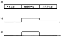
従来技術における光ディスク装置の動作について図8および図9を参照して説明する。図8にブロック構成を示す。図9aに光ディスク装置の動作状態変化の一例を示す。図9bに切替タイミング生成部30から出力される信号の一例を示す。図9cに集光レンズ13の位置変化の一例を示す。図9dにFc位置指示部34から出力される信号の一例を示す。
The operation of the optical disc apparatus in the prior art will be described with reference to FIGS. FIG. 8 shows a block configuration. FIG. 9a shows an example of a change in the operating state of the optical disc apparatus. FIG. 9 b shows an example of a signal output from the switching
図8において、光量検出部17は信号をFE生成部20へ送る。FE生成部20は光量検出部17の信号を用いて、光ビームの光ディスク1の情報面上での収束状態を示す誤差信号、つまり光ディスク1の情報面に対する光ビームの焦点の位置ずれに応じた誤差信号(以下FE信号と呼ぶ)を演算し、Fcフィルタ21へ送る。Fcフィルタ21はFE信号に応じてフォーカス制御を行うための駆動を生成し、Fcアクチュエータ14へ送る。切替タイミング生成部30は光ディスク1に記録を行う際に、記録開始の所定時間手前から記録開始までを記録前状態と定義し、再生状態あるいは記録前状態あるいは記録中状態を示す信号をFc位置指示部34へ送る。記録前Fc位置生成部33は記録前Fc位置を生成しFc位置指示部34に送る。記録Fc位置生成部32は記録中Fc位置を生成しFc位置指示部34に送る。Fc位置指示部34は切替タイミング生成部30からの信号が再生状態の時は内部に有する再生Fc位置を、切替タイミング生成部30からの信号が記録前状態の時は記録前Fc位置生成部33からの記録前Fc位置を、切替タイミング生成部30からの信号が記録中状態の時は記録Fc位置生成部32からの記録中Fc位置を、FE生成部20へ送る。FE生成部20はFc位置指示部34からの信号に基づいてFE信号にオフセットを印加することでフォーカス制御の目標位置を変化させる。
In FIG. 8, the light
半導体レーザ11からの光ビームの波長は発光パワーによって変動する。また、光ヘッド10の中の各素子の屈折率は波長依存性がある。集光レンズ13がガラスでなく樹脂で作られる場合は特に光ビームの波長変化による屈折率変化が大きくなる。そのため、再生発光からパワーを上げて記録発光すると光ビームの波長が変化し、波長変化により焦点位置が変化する。フォーカス制御は集光レンズ13を動かすことで光ビームの焦点を動かしているが、応答性は数kHzのオーダーであり、記録先頭で過渡応答している間は適切なフォーカス状態にならない。
The wavelength of the light beam from the semiconductor laser 11 varies depending on the emission power. Further, the refractive index of each element in the
上記課題を解決するため、特許文献1が示すように記録する前の段階で集光レンズ13の位置を記録時に最適なフォーカス状態が得られるようにあらかじめ動かすという手法がある。
In order to solve the above-described problem, there is a method in which the position of the
図9を用いて説明する。切替タイミング生成部30は図9aに示す光ディスク1への動作状態に応じて図9bに示す状態信号を出力する。Fc位置指示部34は図9dに示すように、実際に記録が始まる前、切替タイミング生成部30からの信号が再生状態から記録前状態に遷移したときと切替タイミング生成部30からの信号が記録前状態から記録中状態に遷移したときにFE信号のオフセットを変化させる。切替タイミング生成部30からの信号が再生状態と記録前状態にある場合は、半導体レーザ11からは再生レベルの光ビームが発光される。切替タイミング生成部30からの信号が再生状態から記録前状態に遷移したときにFE信号のオフセットを変化させることで、集光レンズ13を記録中にあるべき位置にさせる。また、切替タイミング生成部30からの信号が記録中状態にある場合は、半導体レーザ11からは記録用パワーの光ビームが発光される。切替タイミング生成部30からの信号が記録前状態から記録中状態に遷移したときにFE信号のオフセットを変化させることで、記録再生による回路オフセットなどの変化要因を打ち消し、集光レンズ13がほぼ同じ位置を保つようにさせる。
This will be described with reference to FIG. The switching
このように、実際に記録を行う前に、あらかじめFE信号にオフセットを加えることで、記録に突入した際のフォーカス状態は良化する。しかしながら、どのようにしてあらかじめFE信号に加えるオフセット量を求めるか不明であり、また、オフセットを加えたことにより記録直前の再生におけるフォーカス状態は悪化し再生動作に影響が発生する。 In this way, by adding an offset to the FE signal in advance before actually recording, the focus state when entering the recording is improved. However, it is unclear how to obtain the offset amount to be added to the FE signal in advance, and the addition of the offset deteriorates the focus state in the reproduction immediately before recording and affects the reproduction operation.
集光レンズ13の応答性は倍速によってあまり変化しないため、高倍速になるほど悪化したフォーカス状態で再生動作を行うデータ量が増加し、データ化け等が発生する。
Since the responsiveness of the
特にBlu−rayディスクは使用するNAが大きいことより、フォーカス状態の悪化に対する再生信号の悪化影響が大きい。 In particular, the Blu-ray disc has a large NA to be used, so that the reproduction signal has a great influence on the deterioration of the focus state.
今後、行われるBlu−rayディスク対応ドライブの低価格化に応じて、集光レンズ13の樹脂化は避けられない状況であり、本課題の対策が必要となる。
In the future, as the price of Blu-ray disc compatible drives will be reduced, it is inevitable that the condensing
本発明は上述した課題を解決するためになされたものであり、記録前にフォーカス制御目標位置を変更する際の再生特性劣化を抑制することができる光ディスク装置を提供することを目的とする。 The present invention has been made to solve the above-described problems, and an object of the present invention is to provide an optical disc apparatus capable of suppressing deterioration in reproduction characteristics when a focus control target position is changed before recording.
本発明の請求項1に係る光ディスク装置では、情報担体の情報面あるいは表面に対する光ビームの焦点の位置ずれに応じた信号を検出するフォーカス誤差検出手段と、フォーカス誤差検出手段の信号に応じて、光ビームの焦点が情報担体の情報面を追従するように、光ビームの収束状態を変化させるフォーカス制御手段と、情報担体に対して記録再生を行う動作に応じて再生状態、記録前状態、記録中状態の3状態を出力する切替タイミング生成手段と、切替タイミング生成手段からの信号が記録前状態から記録中状態に遷移した際のフォーカス誤差検出手段の信号に応じて集光レンズの変動量を出力するレンズ位置検出手段と、情報担体に対して記録再生を行う動作に応じて再生状態、記録前状態、記録中状態の3状態におけるフォーカス制御目標位置を保持し、切替タイミング生成手段からの信号に応じてフォーカス制御目標位置を変更する信号をフォーカス誤差検出手段へ出力するフォーカス位置変更手段とを備え、フォーカス位置変更手段はレンズ位置検出手段からの集光レンズの変動量に応じて記録前におけるフォーカス制御目標位置を変更することを特徴とする。 In the optical disc device according to claim 1 of the present invention, the focus error detecting means for detecting a signal corresponding to the positional deviation of the focal point of the light beam with respect to the information surface or surface of the information carrier, and according to the signal of the focus error detecting means, Focus control means for changing the convergence state of the light beam so that the focal point of the light beam follows the information surface of the information carrier, and the reproduction state, the pre-recording state, and the recording according to the operation of recording and reproducing the information carrier The change amount of the condensing lens according to the signal of the switching timing generation means for outputting the three states of the intermediate state and the focus error detection means when the signal from the switching timing generation means transits from the pre-recording state to the recording state. Lens position detection means for output, and focus in three states of a reproduction state, a pre-recording state, and a recording state in accordance with the operation of recording and reproducing information carrier A focus position changing means for holding a target position and outputting a signal for changing the focus control target position in accordance with a signal from the switching timing generating means to the focus error detecting means. The focus position changing means is a lens position detecting means. The focus control target position before recording is changed in accordance with the fluctuation amount of the condenser lens from.
さらに、本発明の請求項2に係る光ディスク装置では、切替タイミング生成手段からの信号が記録前状態を示す区間でサーボパラメータを変更するサーボパラメータ変更手段とを備えたことを特徴とする。 Furthermore, the optical disk apparatus according to claim 2 of the present invention is characterized by comprising servo parameter changing means for changing servo parameters in a section in which a signal from the switching timing generating means indicates a pre-recording state.
さらに、本発明の請求項3に係る光ディスク装置では、光ビームと情報担体上のトラックとの位置ずれに応じた信号を検出するトラック誤差検出手段とを備え、サーボパラメータ変更手段はトラック誤差検出手段の検出ゲインを変更することを特徴とする。
The optical disk apparatus according to
さらに、本発明の請求項4に係る光ディスク装置では、光ビームと情報担体上のトラックとの位置ずれに応じた信号を検出するトラック誤差検出手段とを備え、サーボパラメータ変更手段はトラック誤差検出手段のオフセットを変更することを特徴とする。 Furthermore, the optical disk apparatus according to claim 4 of the present invention further comprises track error detecting means for detecting a signal corresponding to the positional deviation between the light beam and the track on the information carrier, and the servo parameter changing means is track error detecting means. The offset is changed.
さらに、本発明の請求項5に係る光ディスク装置では、サーボパラメータ変更手段はサーボ信号検出の回路オフセットの印加量を変更することを特徴とする。 Furthermore, the optical disk apparatus according to claim 5 of the present invention is characterized in that the servo parameter changing means changes the application amount of the circuit offset for servo signal detection.
さらに、本発明の請求項6に係る光ディスク装置では、サーボパラメータ変更手段は光ビームに与える球面収差量を変更することを特徴とする。 Further, in the optical disk apparatus according to claim 6 of the present invention, the servo parameter changing means changes the amount of spherical aberration given to the light beam.
さらに、本発明の請求項7に係る光ディスク装置では、切替タイミング生成手段からの信号が再生状態から記録前状態に遷移した際のフォーカス誤差検出手段からの信号の過渡応答整定時間に応じて、切替タイミング生成手段が再生状態から記録前状態に遷移するタイミングを変更するタイミング変更手段とを備えたことを特徴とする。 Further, in the optical disc apparatus according to claim 7 of the present invention, the switching is performed according to the transient response settling time of the signal from the focus error detecting means when the signal from the switching timing generating means transits from the reproduction state to the pre-recording state. The timing generation means includes timing change means for changing the timing of transition from the reproduction state to the pre-recording state.
さらに、本発明の請求項8に係る光ディスク装置では、フォーカス制御手段は切替タイミング生成手段からの信号が再生状態から記録前状態に遷移するとフォーカス制御ゲインを上げることを特徴とする。 Furthermore, the optical disc apparatus according to claim 8 of the present invention is characterized in that the focus control means increases the focus control gain when the signal from the switching timing generation means transitions from the reproduction state to the pre-recording state.
さらに、本発明の請求項9に係る光ディスク装置では、フォーカス制御手段は切替タイミング生成手段からの信号が再生状態から記録前状態に遷移してフォーカス制御ゲインを上げた後、フォーカス誤差検出手段からの信号が整定するとフォーカス制御ゲインを戻すことを特徴とする。 Further, in the optical disc apparatus according to claim 9 of the present invention, the focus control means is configured to output the focus error detection means from the focus error detection means after the signal from the switching timing generation means transits from the reproduction state to the pre-recording state to increase the focus control gain. When the signal is settled, the focus control gain is returned.
さらに、本発明の請求項10に係る光ディスク装置では、切替タイミング生成手段からの信号が再生状態から記録前状態に遷移した際のフォーカス位置変更手段からの信号のオーバーシュートさせるなど過渡応答波形を補正する信号補正手段とを備えたことを特徴とする。 Further, in the optical disc apparatus according to claim 10 of the present invention, the transient response waveform is corrected by, for example, overshooting the signal from the focus position changing unit when the signal from the switching timing generating unit transitions from the reproduction state to the pre-recording state. And a signal correcting means.
さらに、本発明の請求項11に係る光ディスク装置では、信号補正手段は切替タイミング生成手段からの信号が再生状態から記録前状態に遷移してから所定時間の間、フォーカス位置変更手段からの信号の変化分を所定倍することを特徴とする。 Further, in the optical disk apparatus according to claim 11 of the present invention, the signal correction means is configured to detect the signal from the focus position changing means for a predetermined time after the signal from the switching timing generating means transitions from the reproduction state to the pre-recording state. It is characterized by multiplying the change by a predetermined amount.
さらに、本発明の請求項12に係る光ディスク装置では、レンズ位置検出手段は切替タイミング生成手段からの信号が再生状態から記録前状態に遷移した際のフォーカス誤差検出手段の信号に応じて集光レンズの変動量を信号補正手段へ出力し、信号補正手段はレンズ位置検出手段からの集光レンズの変動量に応じて信号補正することを特徴とする。 Further, in the optical disc apparatus according to claim 12 of the present invention, the lens position detecting means is a condensing lens according to the signal of the focus error detecting means when the signal from the switching timing generating means transitions from the reproduction state to the pre-recording state. Is output to the signal correction means, and the signal correction means corrects the signal according to the fluctuation amount of the condenser lens from the lens position detection means.
さらに、本発明の請求項13に係る光ディスク装置では、レンズ位置検出手段は切替タイミング生成手段からの信号が記録前状態から記録中状態に遷移した際のフォーカス誤差検出手段の信号に応じて集光レンズの変動量を信号補正手段へ出力し、信号補正手段はレンズ位置検出手段からの集光レンズの変動量に応じて信号補正することを特徴とする。 Further, in the optical disc apparatus according to claim 13 of the present invention, the lens position detecting means collects light according to the signal of the focus error detecting means when the signal from the switching timing generating means transits from the pre-recording state to the recording state. The variation amount of the lens is output to the signal correction unit, and the signal correction unit corrects the signal according to the variation amount of the condenser lens from the lens position detection unit.
さらに、本発明の請求項14に係る光ディスク装置では、フォーカス位置変更手段が保持する再生のフォーカス制御目標位置と記録前のフォーカス制御目標位置の差分が所定値以上の場合、記録再生倍速を制限する倍速制限手段とを備えたことを特徴とする。 Furthermore, in the optical disk apparatus according to claim 14 of the present invention, when the difference between the reproduction focus control target position held by the focus position changing means and the focus control target position before recording is a predetermined value or more, the recording / reproduction double speed is limited. And a double speed limiting means.
さらに、本発明の請求項15に係る光ディスク装置では、フォーカス位置変更手段が保持する再生のフォーカス制御目標位置と記録前のフォーカス制御目標位置の差分が所定値以上の場合、記録と再生それぞれの動作の間に検索動作が入る動作状態となり、フォーカス位置変更手段が保持する再生のフォーカス制御目標位置と記録前のフォーカス制御目標位置の差分が所定値より小さい場合、記録から再生の間のみ検索動作が入る動作状態となる記録再生動作変更手段とを備えたことを特徴とする。 Furthermore, in the optical disc apparatus according to claim 15 of the present invention, when the difference between the focus control target position for reproduction held by the focus position changing means and the focus control target position before recording is greater than or equal to a predetermined value, the recording and reproduction operations are performed. If the difference between the playback focus control target position held by the focus position changing means and the focus control target position before recording is smaller than a predetermined value, the search operation is performed only during recording to playback. The recording / reproducing operation changing means for entering the operating state is provided.
さらに、本発明の請求項16に係る光ディスク装置では、フォーカス位置変更手段が保持する再生のフォーカス制御目標位置と記録前のフォーカス制御目標位置の差分が所定値以上の場合、記録から再生の間のみ検索動作が入り、再生から記録の間に記録も再生も検索も行わない動作状態となりフォーカス位置変更手段が保持する再生のフォーカス制御目標位置と記録前のフォーカス制御目標位置の差分が所定値より小さい場合、記録から再生の間のみ検索動作が入り、再生から記録に連続動作する動作状態となる記録再生動作変更手段とを備えたことを特徴とする。 Further, in the optical disc apparatus according to claim 16 of the present invention, when the difference between the focus control target position for reproduction held by the focus position changing means and the focus control target position before recording is equal to or larger than a predetermined value, only during the period from recording to reproduction. A search operation is entered, and no recording, playback, or search is performed between playback and recording. The difference between the focus control target position for playback held by the focus position changing means and the focus control target position before recording is smaller than a predetermined value. In this case, there is provided a recording / reproducing operation changing means that enters a search operation only during recording to reproduction and enters an operation state in which continuous operation is performed from reproduction to recording.
さらに、本発明の請求項17に係る光ディスク装置では、フォーカス位置変更手段は記録時の光ビーム発光パワー平均値に応じて、記録前におけるフォーカス制御目標位置を変更することを特徴とする。 Further, in the optical disc apparatus according to claim 17 of the present invention, the focus position changing means changes the focus control target position before recording according to the average value of the light beam emission power at the time of recording.
さらに、本発明の請求項18に係る光ディスク装置では、レンズ位置検出手段は切替タイミング生成手段からの信号の変化タイミングにおいてフォーカス誤差検出手段からの信号を1回取得することを特徴とする。 Further, in the optical disk apparatus according to claim 18 of the present invention, the lens position detecting means acquires the signal from the focus error detecting means once at the change timing of the signal from the switching timing generating means.
さらに、本発明の請求項19に係る光ディスク装置では、レンズ位置検出手段は切替タイミング生成手段からの信号の変化タイミングからフォーカス誤差検出手段からの信号を所定時間積分して取得することを特徴とする。 Further, in the optical disc apparatus according to claim 19 of the present invention, the lens position detection means acquires the signal from the focus error detection means by integrating for a predetermined time from the change timing of the signal from the switching timing generation means. .
さらに、本発明の請求項20に係る光ディスク装置では、レンズ位置検出手段は積分する所定時間は、フォーカス誤差検出手段からの信号が整定するまでの時間とすることを特徴とする。 Further, in the optical disk apparatus according to claim 20 of the present invention, the predetermined time for the integration of the lens position detecting means is a time until the signal from the focus error detecting means is settled.
本発明の請求項1に係る光ディスク装置では、情報担体の情報面あるいは表面に対する光ビームの焦点の位置ずれに応じた信号を検出するフォーカス誤差検出手段と、フォーカス誤差検出手段の信号に応じて、光ビームの焦点が情報担体の情報面を追従するように、光ビームの収束状態を変化させるフォーカス制御手段と、情報担体に対して記録再生を行う動作に応じて再生状態、記録前状態、記録中状態の3状態を出力する切替タイミング生成手段と、切替タイミング生成手段からの信号が記録前状態から記録中状態に遷移した際のフォーカス誤差検出手段の信号に応じて集光レンズの変動量を出力するレンズ位置検出手段と、情報担体に対して記録再生を行う動作に応じて再生状態、記録前状態、記録中状態の3状態におけるフォーカス制御目標位置を保持し、切替タイミング生成手段からの信号に応じてフォーカス制御目標位置を変更する信号をフォーカス誤差検出手段へ出力するフォーカス位置変更手段とを備え、フォーカス位置変更手段はレンズ位置検出手段からの集光レンズの変動量に応じて記録前におけるフォーカス制御目標位置を変更するので、記録パワーや温度などによって変化する色収差分のフォーカス制御目標位置のずれを正確に計測することができる。 In the optical disc device according to claim 1 of the present invention, the focus error detecting means for detecting a signal corresponding to the positional deviation of the focal point of the light beam with respect to the information surface or surface of the information carrier, and according to the signal of the focus error detecting means, Focus control means for changing the convergence state of the light beam so that the focal point of the light beam follows the information surface of the information carrier, and the reproduction state, the pre-recording state, and the recording according to the operation of recording and reproducing the information carrier The change amount of the condensing lens according to the signal of the switching timing generation means for outputting the three states of the intermediate state and the focus error detection means when the signal from the switching timing generation means transits from the pre-recording state to the recording state. Lens position detection means for output, and focus in three states of a reproduction state, a pre-recording state, and a recording state in accordance with the operation of recording and reproducing information carrier A focus position changing means for holding a target position and outputting a signal for changing the focus control target position in accordance with a signal from the switching timing generating means to the focus error detecting means. The focus position changing means is a lens position detecting means. Since the focus control target position before recording is changed in accordance with the fluctuation amount of the condenser lens from, the shift of the focus control target position corresponding to chromatic aberration that changes depending on the recording power, temperature, etc. can be accurately measured.
さらに、本発明の請求項2に係る光ディスク装置では、切替タイミング生成手段からの信号が記録前状態を示す区間でサーボパラメータを変更するサーボパラメータ変更手段とを備えたので、記録直前にフォーカス制御目標位置変化させたことによる再生特性劣化を抑制することができる。 Further, the optical disc apparatus according to the second aspect of the present invention includes the servo parameter changing means for changing the servo parameter in the section where the signal from the switching timing generating means indicates the pre-recording state. It is possible to suppress the reproduction characteristic deterioration due to the position change.
さらに、本発明の請求項3に係る光ディスク装置では、光ビームと情報担体上のトラックとの位置ずれに応じた信号を検出するトラック誤差検出手段とを備え、サーボパラメータ変更手段はトラック誤差検出手段の検出ゲインを変更するので、記録直前にフォーカス制御目標位置変化させたことによるトラッキング誤差信号振幅劣化を抑制することができる。
The optical disk apparatus according to
さらに、本発明の請求項4に係る光ディスク装置では、光ビームと情報担体上のトラックとの位置ずれに応じた信号を検出するトラック誤差検出手段とを備え、サーボパラメータ変更手段はトラック誤差検出手段のオフセットを変更するので、記録直前にフォーカス制御目標位置変化させたことによるトラッキング誤差信号対称性劣化を抑制することができる。 Furthermore, the optical disk apparatus according to claim 4 of the present invention further comprises track error detecting means for detecting a signal corresponding to the positional deviation between the light beam and the track on the information carrier, and the servo parameter changing means is track error detecting means. Therefore, the tracking error signal symmetry deterioration due to the change of the focus control target position immediately before recording can be suppressed.
さらに、本発明の請求項5に係る光ディスク装置では、サーボパラメータ変更手段はサーボ信号検出の回路オフセットの印加量を変更するので、記録直前にフォーカス制御目標位置変化させたことによるオフセット変化の影響を抑制することができる。 Further, in the optical disk apparatus according to claim 5 of the present invention, the servo parameter changing means changes the application amount of the servo signal detection circuit offset, so that the influence of the offset change due to the change of the focus control target position immediately before recording is affected. Can be suppressed.
さらに、本発明の請求項6に係る光ディスク装置では、サーボパラメータ変更手段は光ビームに与える球面収差量を変更するので、記録直前にフォーカス制御目標位置変化させたことによる球面収差ずれを抑制することができる。 Further, in the optical disk apparatus according to claim 6 of the present invention, the servo parameter changing means changes the amount of spherical aberration given to the light beam, so that the spherical aberration deviation caused by changing the focus control target position immediately before recording is suppressed. Can do.
さらに、本発明の請求項7に係る光ディスク装置では、切替タイミング生成手段からの信号が再生状態から記録前状態に遷移した際のフォーカス誤差検出手段からの信号の過渡応答整定時間に応じて、切替タイミング生成手段が再生状態から記録前状態に遷移するタイミングを変更するタイミング変更手段とを備えたので、フォーカス制御目標位置の変化の整定が早い場合に、フォーカス制御目標位置がずれた再生状態の不要な時間を削減することができる。 Further, in the optical disc apparatus according to claim 7 of the present invention, the switching is performed according to the transient response settling time of the signal from the focus error detecting means when the signal from the switching timing generating means transits from the reproduction state to the pre-recording state. The timing generator has a timing changing unit that changes the timing of transition from the playback state to the pre-recording state, so that when the focus control target position changes quickly, there is no need for a playback state in which the focus control target position is shifted. Time can be saved.
さらに、本発明の請求項8に係る光ディスク装置では、フォーカス制御手段は切替タイミング生成手段からの信号が再生状態から記録前状態に遷移するとフォーカス制御ゲインを上げるので、フォーカス制御目標位置変化の整定を短時間化することができる。 Furthermore, in the optical disc apparatus according to claim 8 of the present invention, the focus control means increases the focus control gain when the signal from the switching timing generation means transitions from the reproduction state to the pre-recording state, so that the focus control target position change is settled. The time can be shortened.
さらに、本発明の請求項9に係る光ディスク装置では、フォーカス制御手段は切替タイミング生成手段からの信号が再生状態から記録前状態に遷移してフォーカス制御ゲインを上げた後、フォーカス誤差検出手段からの信号が整定するとフォーカス制御ゲインを戻すので、フォーカス制御目標位置変化の整定後の不要な残差増加を低減することができる。 Further, in the optical disc apparatus according to claim 9 of the present invention, the focus control means is configured to output the focus error detection means from the focus error detection means after the signal from the switching timing generation means transits from the reproduction state to the pre-recording state to increase the focus control gain. When the signal is settled, the focus control gain is returned, so that it is possible to reduce an unnecessary increase in residual after the focus control target position change is settled.
さらに、本発明の請求項10に係る光ディスク装置では、切替タイミング生成手段からの信号が再生状態から記録前状態に遷移した際のフォーカス位置変更手段からの信号のオーバーシュートさせるなど過渡応答波形を補正する信号補正手段とを備えたので、フォーカス制御目標位置変化の整定を短時間化することができる。 Further, in the optical disc apparatus according to claim 10 of the present invention, the transient response waveform is corrected by, for example, overshooting the signal from the focus position changing unit when the signal from the switching timing generating unit transitions from the reproduction state to the pre-recording state. Since the signal correction means is provided, it is possible to shorten the settling time of the focus control target position change.
さらに、本発明の請求項11に係る光ディスク装置では、信号補正手段は切替タイミング生成手段からの信号が再生状態から記録前状態に遷移してから所定時間の間、フォーカス位置変更手段からの信号の変化分を所定倍するので、簡易な構成でフォーカス制御目標位置変化の整定の短時間化を実現できる。 Further, in the optical disk apparatus according to claim 11 of the present invention, the signal correction means is configured to detect the signal from the focus position changing means for a predetermined time after the signal from the switching timing generating means transitions from the reproduction state to the pre-recording state. Since the amount of change is multiplied by a predetermined amount, it is possible to reduce the time required for setting the focus control target position change with a simple configuration.
さらに、本発明の請求項12に係る光ディスク装置では、レンズ位置検出手段は切替タイミング生成手段からの信号が再生状態から記録前状態に遷移した際のフォーカス誤差検出手段の信号に応じて集光レンズの変動量を信号補正手段へ出力し、信号補正手段はレンズ位置検出手段からの集光レンズの変動量に応じて信号補正するので、フォーカス制御目標位置変化の整定に対する短縮できる時間を増やすことができる。 Further, in the optical disc apparatus according to claim 12 of the present invention, the lens position detecting means is a condensing lens according to the signal of the focus error detecting means when the signal from the switching timing generating means transitions from the reproduction state to the pre-recording state. Is output to the signal correction means, and the signal correction means corrects the signal in accordance with the fluctuation amount of the condenser lens from the lens position detection means, so that it is possible to increase the time that can be shortened for settling of the focus control target position change. it can.
さらに、本発明の請求項13に係る光ディスク装置では、レンズ位置検出手段は切替タイミング生成手段からの信号が記録前状態から記録中状態に遷移した際のフォーカス誤差検出手段の信号に応じて集光レンズの変動量を信号補正手段へ出力し、信号補正手段はレンズ位置検出手段からの集光レンズの変動量に応じて信号補正するので、フォーカス制御目標位置変化の整定に対する短縮できる時間を増やすことができる。 Further, in the optical disc apparatus according to claim 13 of the present invention, the lens position detecting means collects light according to the signal of the focus error detecting means when the signal from the switching timing generating means transits from the pre-recording state to the recording state. The lens fluctuation amount is output to the signal correction means, and the signal correction means corrects the signal according to the fluctuation amount of the condenser lens from the lens position detection means, so that the time that can be shortened for the stabilization of the focus control target position change is increased. Can do.
さらに、本発明の請求項14に係る光ディスク装置では、フォーカス位置変更手段が保持する再生のフォーカス制御目標位置と記録前のフォーカス制御目標位置の差分が所定値以上の場合、記録再生倍速を制限する倍速制限手段とを備えたので、記録直前にフォーカス制御目標位置変化させたことによる再生エラーを防ぐことができる。 Furthermore, in the optical disk apparatus according to claim 14 of the present invention, when the difference between the reproduction focus control target position held by the focus position changing means and the focus control target position before recording is a predetermined value or more, the recording / reproduction double speed is limited. Since the double speed limiting means is provided, it is possible to prevent a reproduction error caused by changing the focus control target position immediately before recording.
さらに、本発明の請求項15に係る光ディスク装置では、フォーカス位置変更手段が保持する再生のフォーカス制御目標位置と記録前のフォーカス制御目標位置の差分が所定値以上の場合、記録と再生それぞれの動作の間に検索動作が入る動作状態となり、フォーカス位置変更手段が保持する再生のフォーカス制御目標位置と記録前のフォーカス制御目標位置の差分が所定値より小さい場合、記録から再生の間のみ検索動作が入る動作状態となる記録再生動作変更手段とを備えたので、記録直前にフォーカス制御目標位置変化させたことによる再生エラーを防ぐことができる。 Furthermore, in the optical disc apparatus according to claim 15 of the present invention, when the difference between the focus control target position for reproduction held by the focus position changing means and the focus control target position before recording is greater than or equal to a predetermined value, the recording and reproduction operations are performed. If the difference between the playback focus control target position held by the focus position changing means and the focus control target position before recording is smaller than a predetermined value, the search operation is performed only during recording to playback. Since the recording / reproducing operation changing means for entering the operation state is provided, it is possible to prevent a reproduction error caused by changing the focus control target position immediately before recording.
さらに、本発明の請求項16に係る光ディスク装置では、フォーカス位置変更手段が保持する再生のフォーカス制御目標位置と記録前のフォーカス制御目標位置の差分が所定値以上の場合、記録から再生の間のみ検索動作が入り、再生から記録の間に記録も再生も検索も行わない動作状態となりフォーカス位置変更手段が保持する再生のフォーカス制御目標位置と記録前のフォーカス制御目標位置の差分が所定値より小さい場合、記録から再生の間のみ検索動作が入り、再生から記録に連続動作する動作状態となる記録再生動作変更手段とを備えたので、記録直前にフォーカス制御目標位置変化させたことによる再生エラーを防ぐことができる。 Further, in the optical disc apparatus according to claim 16 of the present invention, when the difference between the focus control target position for reproduction held by the focus position changing means and the focus control target position before recording is equal to or larger than a predetermined value, only during the period from recording to reproduction. A search operation is entered, and no recording, playback, or search is performed between playback and recording. The difference between the focus control target position for playback held by the focus position changing means and the focus control target position before recording is smaller than a predetermined value. In this case, there is provided a recording / playback operation changing means that enters a search operation only during recording and playback and is in an operation state in which continuous operation is performed from playback to recording, so that a playback error caused by changing the focus control target position immediately before recording is provided. Can be prevented.
さらに、本発明の請求項17に係る光ディスク装置では、フォーカス位置変更手段は記録時の光ビーム発光パワー平均値に応じて、記録前におけるフォーカス制御目標位置を変更するので、記録パワーや温度などによって変化する色収差分のフォーカス制御目標位置ずれの計測前誤差を低減することができる。 Furthermore, in the optical disc apparatus according to claim 17 of the present invention, the focus position changing means changes the focus control target position before recording according to the average value of the light beam emission power at the time of recording. It is possible to reduce a pre-measurement error of the focus control target position shift corresponding to the changing chromatic aberration.
さらに、本発明の請求項18に係る光ディスク装置では、レンズ位置検出手段は切替タイミング生成手段からの信号の変化タイミングにおいてフォーカス誤差検出手段からの信号を1回取得するので、簡易な構成で色収差分のフォーカス制御目標位置ずれを計測することができる。 Furthermore, in the optical disk apparatus according to the eighteenth aspect of the present invention, the lens position detection means obtains the signal from the focus error detection means once at the change timing of the signal from the switching timing generation means. It is possible to measure the focus control target position deviation.
さらに、本発明の請求項19に係る光ディスク装置では、レンズ位置検出手段は切替タイミング生成手段からの信号の変化タイミングからフォーカス誤差検出手段からの信号を所定時間積分して取得するので、色収差分のフォーカス制御目標位置ずれを計測精度を向上することができる。 Furthermore, in the optical disc apparatus according to claim 19 of the present invention, the lens position detecting means obtains the signal from the focus error detecting means by integrating for a predetermined time from the change timing of the signal from the switching timing generating means. The measurement accuracy of the focus control target position deviation can be improved.
さらに、本発明の請求項20に係る光ディスク装置では、レンズ位置検出手段は積分する所定時間は、フォーカス誤差検出手段からの信号が整定するまでの時間とするので、色収差分のフォーカス制御目標位置ずれを計測精度を向上することができる。 Furthermore, in the optical disk apparatus according to claim 20 of the present invention, the predetermined time for the integration of the lens position detection means is the time until the signal from the focus error detection means is settled. The measurement accuracy can be improved.
以下、本発明の実施の形態について、図面を参照しながら説明する。 Hereinafter, embodiments of the present invention will be described with reference to the drawings.
(実施の形態1)
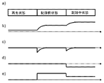
本実施の形態1である光ディスク装置の動作について図1および図2および図3を参照して説明する。図1にブロック構成を示す。図2aに切替タイミング生成部30から出力される信号の一例を示す。図2bに集光レンズ13の位置変化の一例を示す。図2cにFE生成部20から出力される信号の一例を示す。図2dに過渡応答検出部31から出力される信号の一例を示す。図2eにFc位置指示部34から出力される信号の一例を示す。
(Embodiment 1)
The operation of the optical disk apparatus according to the first embodiment will be described with reference to FIGS. 1, 2, and 3. FIG. FIG. 1 shows a block configuration. FIG. 2 a shows an example of a signal output from the switching
図1において、フォーカス誤差検出手段は光量検出部17およびFE生成部20である。フォーカス制御手段はFcフィルタ21である。切替タイミング生成手段は切替タイミング生成部30である。レンズ位置検出手段は過渡応答検出部31である。フォーカス位置変更手段はFc位置指示部34および記録Fc位置生成部32および記録前Fc位置生成部33である。サーボパラメータ変更手段は球面収差発生部16および球面収差指示部40である。
In FIG. 1, the focus error detection means is a light
図1において、背景技術である図8の構成要素と同じものには同一の番号を付して説明を省略する。FE生成部20は光量検出部17の信号を用いて、光ビームの光ディスク1の情報面上での収束状態を示す誤差信号、つまり光ディスク1の情報面に対する光ビームの焦点の位置ずれに応じたFE信号を演算し、Fcフィルタ21および過渡応答検出部31へ送る。切替タイミング生成部30は光ディスク1に記録を行う際に、記録開始の所定時間手前から記録開始までを記録前状態と定義し、再生状態あるいは記録前状態あるいは記録中状態を示す信号を過渡応答検出部31およびFc位置指示部34および球面収差指示部40へ送る。過渡応答検出部31は切替タイミング生成部30からの信号が記録前状態から記録中状態に遷移したときのFE信号変化量を測定して記録前Fc位置生成部33へ送る。記録前Fc位置生成部33は過渡応答検出部31からの信号に所定ゲインを乗じて現状の記録前Fc位置に加算し、検出されるフォーカス制御目標位置のずれを補正し、Fc位置指示部34へ送る。球面収差指示部40は切替タイミング生成部30からの信号が再生状態あるいは記録中状態である場合に、内部に有する通常球面収差位置を、切替タイミング生成部30からの信号が記録前状態である場合に、内部に有する記録前球面収差位置を、球面収差発生部16へ送る。球面収差発生部16は球面収差指示部40からの球面収差位置に応じて光ビームに球面収差を与える。
In FIG. 1, the same components as those in FIG. The
図2bに示すように切替タイミング生成部30からの信号が再生状態から記録前状態に遷移した際の集光レンズ13に対する事前の移動量が不足している場合には、切替タイミング生成部30からの信号が記録前状態から記録中状態に遷移した際に、集光レンズ13の位置に過渡応答が残る。したがって、FE信号にも図2cに示すように、切替タイミング生成部30からの信号が記録前状態から記録中状態に遷移した際に過渡応答が観測される。
As shown in FIG. 2b, when the amount of advance movement with respect to the
過渡応答検出部31は、図2dに示すように、切替タイミング生成部30からの信号が記録前状態から記録中状態に遷移した際のFE信号を変化を取得してラッチする。記録前Fc位置生成部33は過渡応答検出部31からの信号が負であれば、記録前Fc位置を増加させ、過渡応答検出部31からの信号が正であれば、記録前Fc位置を減少させる。
As shown in FIG. 2d, the transient
切替タイミング生成部30からの信号が記録前状態を示している間はFc位置の変化によってフォーカス状態が悪化する。光ビームに対する球面収差量の最適量はフォーカス状態によって変化する。そのため、切替タイミング生成部30からの信号が記録前状態を示している間は、球面収差発生部16が発生させる球面収差が、変化したフォーカス状態に応じて最適量となるように、球面収差指示部40が信号を変化させる。
While the signal from the switching
このようにしてFE信号を測定して記録前に行うFc位置の変化量を制御することで、記録に突入した際のフォーカス制御の過渡応答を低減できる。また、記録前に行うFc位置の変化に応じた球面収差量を発生させることで、記録直前の再生状態の悪化を低減できる。 Thus, by measuring the FE signal and controlling the amount of change in the Fc position performed before recording, it is possible to reduce the transient response of the focus control when entering the recording. Further, by generating a spherical aberration amount corresponding to the change in the Fc position performed before recording, it is possible to reduce the deterioration of the reproduction state immediately before recording.
尚、本実施例1では、球面収差量を変化させることで記録直前の再生特性を良化させたが、トラッキング制御のゲインあるいはオフセットあるいは回路系の検出オフセットを変化させることで記録直前の再生特性を良化させてもよい。また、本実施例1では、実際に記録に突入するタイミングのFE信号を測定したが、実際に記録に突入するタイミングから所定時間の間、FE信号を積分して測定してもよい。さらにその際の測定時間は固定でもよいし、FE信号が整定したことを検出するまで測定してもよい。さらにFE信号が所定時間の間、所定範囲に収まることを検出したら、FE信号が整定したと判断してもよい。また、本実施例1では、FE信号により記録前Fc位置を求めていたが、初期値として、記録する際の記録パワーの平均値と半導体レーザ11の波長変動特性と集光レンズ13の波長依存性から記録前Fc位置を求めてもよい。
In the first embodiment, the reproduction characteristic immediately before recording is improved by changing the amount of spherical aberration, but the reproduction characteristic immediately before recording is changed by changing the gain or offset of tracking control or the detection offset of the circuit system. May be improved. In the first embodiment, the FE signal at the timing of actually entering recording is measured, but the FE signal may be integrated and measured for a predetermined time from the timing of actually entering recording. Furthermore, the measurement time at that time may be fixed, or may be measured until it is detected that the FE signal has settled. Further, when it is detected that the FE signal falls within a predetermined range for a predetermined time, it may be determined that the FE signal has settled. In the first embodiment, the pre-recording Fc position is obtained from the FE signal. As an initial value, the average value of the recording power at the time of recording, the wavelength variation characteristic of the semiconductor laser 11, and the wavelength dependence of the
(実施の形態2)
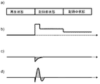
本実施の形態2である光ディスク装置の動作について図4および図5を参照して説明する。図4にブロック構成を示す。図5aに切替タイミング生成部50から出力される信号の一例を示す。図5bにFc位置指示部34から出力される信号の一例を示す。図5cに過渡応答少ない場合にFE生成部20から出力される信号の一例を示す。図5dに過渡応答多い場合にFE生成部20から出力される信号の一例を示す。
(Embodiment 2)
The operation of the optical disk apparatus according to the second embodiment will be described with reference to FIGS. FIG. 4 shows a block configuration. FIG. 5 a shows an example of a signal output from the switching
図1において、フォーカス誤差検出手段は光量検出部17およびFE生成部20である。フォーカス制御手段はFcフィルタ21である。切替タイミング生成手段は切替タイミング生成部50である。レンズ位置検出手段は過渡応答検出部31および過渡応答検出部52である。フォーカス位置変更手段はFc位置指示部34および記録Fc位置生成部32および記録前Fc位置生成部33である。タイミング変更手段は整定時間検出部51である。信号補正手段は信号補正部53である。
In FIG. 1, the focus error detection means is a light
図4において、背景技術である図8および実施例1である図1の構成要素と同じものには同一の番号を付して説明を省略する。FE生成部20は光量検出部17の信号を用いて、光ビームの光ディスク1の情報面上での収束状態を示す誤差信号、つまり光ディスク1の情報面に対する光ビームの焦点の位置ずれに応じたFE信号を演算し、Fcフィルタ21および過渡応答検出部31および整定時間検出部51および過渡応答検出部52へ送る。整定時間検出部51は切替タイミング生成部50からの信号が再生状態から記録前状態に遷移したタイミングを基準にして、FE信号の微分の絶対値が所定時間の間、所定値以下になるまでの時間を計測して、切替タイミング生成部50へ送る。切替タイミング生成部50は光ディスク1に記録を行う際に、記録開始の所定時間手前から記録開始までを記録前状態と定義し、再生状態あるいは記録前状態あるいは記録中状態を示す信号を過渡応答検出部31およびFc位置指示部34および信号補正部53および整定時間検出部51および過渡応答検出部52へ送る。また、切替タイミング生成部50は整定時間検出部51からの計測時間を、記録前状態の時間幅として設定する。過渡応答検出部52は切替タイミング生成部50からの信号が再生状態から記録前状態に遷移したときのFE信号を所定時間積分測定して信号補正部53へ送る。Fc位置指示部34は切替タイミング生成部50からの信号が再生状態の時は内部に有する再生Fc位置を、切替タイミング生成部50からの信号が記録前状態の時は記録前Fc位置生成部33からの記録前Fc位置を、切替タイミング生成部50からの信号が記録中状態の時は記録Fc位置生成部32からの記録中Fc位置を、信号補正部53へ送る。信号補正部53は切替タイミング生成部50からの信号が再生状態から記録前状態に遷移してから所定時間の間、Fc位置指示部34からの信号の変化分を所定倍してFE生成部20へ送る。また、信号補正部53は過渡応答検出部52からの信号に応じて上記所定倍の倍率を変化させる。
In FIG. 4, the same components as those in FIG. 8 which is the background art and those in FIG. The
背景技術で図9dに示したようにFc位置を単純ステップ状に変化させるのに対して、図5bに示すような2段階ステップ状に変化させることで、フォーカス制御の過渡応答が変化する。 While the Fc position is changed in a simple step shape as shown in FIG. 9d in the background art, the transient response of the focus control is changed by changing it in a two-step step shape as shown in FIG. 5b.
集光レンズ13が重いなどの理由によりフォーカス制御の過渡応答が遅い場合は、FE信号は図5cに示すような波形となる。過渡応答検出部52は所定時間積分することで、ハッチングした領域を測定する。この場合、測定結果は負となるので、信号補正部53は所定倍の倍率を上げる。
When the transient response of the focus control is slow because the
集光レンズ13が軽いなどの理由によりフォーカス制御の過渡応答が速い場合は、FE信号は図5dに示すような波形となる。過渡応答検出部52は所定時間積分することで、ハッチングした領域を測定する。この場合、測定結果は正となるので、信号補正部53は所定倍の倍率を下げる。
When the transient response of the focus control is fast because the
フォーカス制御の過渡応答は遅すぎても速すぎても整定に時間がかかる。上記のように信号補正部53が最適な補正を行うことで整定に要する時間は短縮できる。整定時間検出部51はFE信号の微分の絶対値が所定時間の間、所定値以下になるとフォーカス制御が整定したと判断して、切替タイミング生成部50からの信号が再生状態から記録前状態に遷移するタイミングを遅らせて、フォーカス状態が悪化する時間を短縮する。
The transient response of the focus control takes time to settle whether it is too slow or too fast. As described above, the time required for settling can be shortened by the
このようにして、信号補正部53がFE生成部20に与えるオフセット量の変化波形を補正することで、フォーカス制御過渡応答の整定時間を短縮し、また整定時間短縮により、切替タイミング生成部50からの信号が再生状態から記録前状態に遷移するタイミングを遅らせて、フォーカス状態が悪化している時間を短縮して再生特性の劣化を低減することができる。
In this way, by correcting the change waveform of the offset amount given to the
尚、本実施例2では、Fc位置指示部34からの信号を補正することでフォーカス制御の過渡応答時間を短縮したが、一時的にFcフィルタ21のゲインを上げてフォーカス制御の過渡応答時間を短縮してもよい。さらにその際にFcフィルタ21のゲインを戻すタイミングはFE信号が整定したことを検出するタイミングとしてもよい。また、本実施例2では、切替タイミング生成部50からの信号が再生状態から記録前状態に遷移する際の過渡応答を過渡応答検出部52が測定したが、切替タイミング生成部50からの信号が記録前状態から記録中状態に遷移する際の過渡応答を過渡応答検出部52が測定してもよい。また、本実施例2では、FE信号により記録前Fc位置を求めていたが、初期値として、記録する際の記録パワーの平均値と半導体レーザ11の波長変動特性と集光レンズ13の波長依存性から記録前Fc位置を求めてもよい。また、本実施例2では、FE信号の微分の絶対値が所定時間の間、所定値以下になると、FE信号が整定したと判断したが、FE信号が所定時間の間、所定範囲に収まることを検出すると、FE信号が整定したと判断してもよい。また、本実施例2では、FE信号に加える過渡応答時のオフセット量を変化させていたが、FE信号に加える過渡応答時のオフセット時間を変化させてもよい。また、本実施例2では、FE信号に加えるオフセット量を2段階のステップ変化によってフォーカス制御の過渡応答を低減したが、2段階以上に分割した変化でもよい。
In the second embodiment, the transient response time of the focus control is shortened by correcting the signal from the Fc
(実施の形態3)
本実施の形態3である光ディスク装置の動作について図6を参照して説明する。図6にブロック構成を示す。
(Embodiment 3)
The operation of the optical disk apparatus according to the third embodiment will be described with reference to FIG. FIG. 6 shows a block configuration.
図6において、フォーカス誤差検出手段は光量検出部17およびFE生成部20である。フォーカス制御手段はFcフィルタ21である。切替タイミング生成手段は切替タイミング生成部30である。レンズ位置検出手段は過渡応答検出部31である。フォーカス位置変更手段はFc位置指示部34および記録Fc位置生成部32および記録前Fc位置生成部33である。倍速制限手段は倍速指示部60である。
In FIG. 6, the focus error detection means is a light
図6において、背景技術である図8および実施例1である図1の構成要素と同じものには同一の番号を付して説明を省略する。記録前Fc位置生成部33は過渡応答検出部31からの信号に所定ゲインを乗じて現状の記録前Fc位置に加算し、検出されるフォーカス制御目標位置のずれを補正し、Fc位置指示部34および倍速指示部60へ送る。倍速指示部60は記録前Fc位置生成部33からの信号が大きい場合に光ディスク1に記録再生を行う倍速上限を下げる。また、倍速指示部60は倍速状態に従いモータ61への駆動信号を出力する。モータ61は倍速指示部60からの駆動信号に基づいて光ディスク1を回転させる。
In FIG. 6, the same components as those in FIG. 8 which is the background art and those in FIG. The pre-recording Fc
記録直前にフォーカス状態が悪化して再生特性が悪化する。この課題は切替タイミング生成部30からの信号が再生状態から記録状態に遷移する際に変化するFc位置の量、すなわち記録前Fc位置生成部33からの信号の量に依存して大きくなる。倍速指示部60は記録前Fc位置生成部33からの信号が所定値以上である場合に、記録再生を行う倍速の上限を制限して、制限した倍速を越えている場合、倍速下げる動作を行い、モータ61を低回転にする。
Just before recording, the focus state deteriorates and the reproduction characteristics deteriorate. This problem increases depending on the amount of Fc position that changes when the signal from the switching
このようにして、倍速を制限することで記録前に行うFc位置変化が大きい際のデータ化けを抑制することができる。 In this way, by limiting the double speed, garbled data when the Fc position change is large before recording can be suppressed.
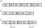
尚、本実施例3では、倍速を制限することで記録前に行うFc位置変化の影響を低減したが、記録間に再生動作も記録動作も行わないように構成してもよい。具体的には図7を参照して説明する。図7aに通常の記録再生時における光ディスク装置の動作状態変化の一例を示す。図7bにシームレス再生記録における光ディスク装置の動作状態変化の一例を示す。図7cにギャップつきシームレス再生記録における光ディスク装置の動作状態変化の一例を示す。記録再生に用いるデータバッファRAMが十分である場合は、図7aに示すように記録動作と再生動作の前にかならず検索動作を挿入していたが、低価格化のためにデータバッファ量が減ると検索動作をしている時間割合が増えて転送レートが悪化する。そのため、図7bに示すように、再生動作と記録動作の間の検索動作を削減し連続した動作とするシームレス再生記録を行う。記録前Fc位置生成部33からの信号が所定値以上である場合に、シームレス再生記録ではなく通常の図7aに示すような動作を行うことで、転送レートは下がるが記録直前の再生を安定化させることができる。また、通常記録では転送レート低下が激しい場合は、図7cに示すように、再生動作と記録動作の間の検索動作は削減するが1セクタ等の所定区間を再生動作も記録動作もしない区間とするギャップつきシームレス再生記録を行うことで転送レート低下量を低減できる。
In the third embodiment, the influence of the Fc position change performed before recording is reduced by restricting the double speed. However, the reproducing operation and the recording operation may not be performed between recordings. This will be specifically described with reference to FIG. FIG. 7a shows an example of a change in the operating state of the optical disc apparatus during normal recording / reproduction. FIG. 7b shows an example of a change in the operating state of the optical disc apparatus in seamless playback recording. FIG. 7c shows an example of a change in the operation state of the optical disc apparatus in the seamless reproduction recording with a gap. When the data buffer RAM used for recording / reproduction is sufficient, as shown in FIG. 7a, the search operation is always inserted before the recording operation and the reproduction operation. The rate of time during which search operations are performed increases and the transfer rate deteriorates. Therefore, as shown in FIG. 7b, seamless playback recording is performed in which the search operation between the playback operation and the recording operation is reduced and the operation is continued. When the signal from the pre-recording Fc
本発明は、記録を行うことのできる円盤状の情報担体(以下光ディスクと呼ぶ)に記録あるいは再生を行う際に、記録前にフォーカス制御目標位置(以下Fc位置と呼ぶ)を変更する光ディスク装置に利用可能である。 The present invention provides an optical disc apparatus that changes a focus control target position (hereinafter referred to as an Fc position) before recording when recording or reproduction is performed on a disc-shaped information carrier (hereinafter referred to as an optical disc) capable of recording. Is available.
1 光ディスク
10 光ヘッド
11 半導体レーザ
12 ビームスプリッタ
13 集光レンズ
14 Fcアクチュエータ
15 Tkアクチュエータ
16 球面収差発生部
17 光量検出部
20 FE生成部
21 Fcフィルタ
30 切替タイミング生成部
31 過渡応答検出部
32 記録Fc位置生成部
33 記録前Fc位置生成部
34 Fc位置指示部
40 球面収差指示部
50 切替タイミング生成部
51 整定時間検出部
52 過渡応答検出部
53 信号補正部
60 倍速指示部
61 モータ
DESCRIPTION OF SYMBOLS 1
Claims (20)
Priority Applications (1)
| Application Number | Priority Date | Filing Date | Title |
|---|---|---|---|
| JP2009109200A JP2010257548A (en) | 2009-04-28 | 2009-04-28 | Optical disk device |
Applications Claiming Priority (1)
| Application Number | Priority Date | Filing Date | Title |
|---|---|---|---|
| JP2009109200A JP2010257548A (en) | 2009-04-28 | 2009-04-28 | Optical disk device |
Publications (1)
| Publication Number | Publication Date |
|---|---|
| JP2010257548A true JP2010257548A (en) | 2010-11-11 |
Family
ID=43318294
Family Applications (1)
| Application Number | Title | Priority Date | Filing Date |
|---|---|---|---|
| JP2009109200A Pending JP2010257548A (en) | 2009-04-28 | 2009-04-28 | Optical disk device |
Country Status (1)
| Country | Link |
|---|---|
| JP (1) | JP2010257548A (en) |
-
2009
- 2009-04-28 JP JP2009109200A patent/JP2010257548A/en active Pending
Similar Documents
| Publication | Publication Date | Title |
|---|---|---|
| US7782722B2 (en) | Method of adjusting spherical aberration and focus offset and information recording/reproduction apparatus using the same | |
| US8054732B2 (en) | Optical recording and reproducing apparatus having an optical pickup including a liquid crystal correcting element | |
| US20040228232A1 (en) | Device for controlling focusing of light beam | |
| JP2005332558A (en) | Method for adjusting focus detection means or tracking detection means and optical disc apparatus | |
| JP2004062938A (en) | Spherical aberration correcting device and spherical aberration correcting method | |
| US20090245073A1 (en) | Optical pickup apparatus | |
| JP2010257548A (en) | Optical disk device | |
| JP4264653B2 (en) | Optical disc apparatus, focus bias, and spherical aberration correction value adjustment method | |
| US20080175111A1 (en) | Disc Device and Control Method for the Same | |
| US20080101204A1 (en) | Optical disk device and method for controlling the same. | |
| JP4112331B2 (en) | Optical pickup spherical aberration focusing deviation compensation method and optical pickup device | |
| JP2008299913A (en) | Optical disc apparatus and information recording method thereof | |
| JP4287471B2 (en) | Optical disk device and integrated circuit of optical disk device | |
| US7933182B2 (en) | Optical information recording and reproducing apparatus that sets a movable range of an objective lens based on the type of recording medium | |
| JP2010079945A (en) | Optical disk recording and reproducing device, and method of correcting temperature characteristic of optical pickup of optical disk recording and reproducing device | |
| JP4466884B2 (en) | Optical axis deviation correction apparatus and method | |
| US7751298B2 (en) | Optical disc apparatus | |
| JP2008293606A (en) | Optical pickup device | |
| JP4332799B2 (en) | Optical pickup, disk drive device, and adjustment value detection method for focus bias and spherical aberration in optical pickup | |
| JP2010003340A (en) | Optical disk device and method for controlling seek thereof | |
| US20110051575A1 (en) | Focus jump method and optical disc apparatus | |
| KR100948145B1 (en) | Focus servo control method and apparatus and optical disk drive using same | |
| JP2008192255A (en) | Optical disk device | |
| JP2010205318A (en) | Optical disk device | |
| CN102651222A (en) | Optical disc device |