JP2010279781A - Female connector and connector - Google Patents

Female connector and connector Download PDF

Info

Publication number
JP2010279781A
JP2010279781A JP2010210877A JP2010210877A JP2010279781A JP 2010279781 A JP2010279781 A JP 2010279781A JP 2010210877 A JP2010210877 A JP 2010210877A JP 2010210877 A JP2010210877 A JP 2010210877A JP 2010279781 A JP2010279781 A JP 2010279781A
Authority
JP
Japan
Prior art keywords
handle
adapter
male connector
female connector
peripheral surface
Prior art date
Legal status (The legal status is an assumption and is not a legal conclusion. Google has not performed a legal analysis and makes no representation as to the accuracy of the status listed.)
Granted
Application number
JP2010210877A
Other languages
Japanese (ja)
Other versions
JP5120673B2 (en
Inventor
Naotsugu Ito
尚継 井藤
Takahiko Kunishige
隆彦 国重
Current Assignee (The listed assignees may be inaccurate. Google has not performed a legal analysis and makes no representation or warranty as to the accuracy of the list.)
JMS Co Ltd
Original Assignee
JMS Co Ltd
Priority date (The priority date is an assumption and is not a legal conclusion. Google has not performed a legal analysis and makes no representation as to the accuracy of the date listed.)
Filing date
Publication date
Application filed by JMS Co Ltd filed Critical JMS Co Ltd
Priority to JP2010210877A priority Critical patent/JP5120673B2/en
Publication of JP2010279781A publication Critical patent/JP2010279781A/en
Application granted granted Critical
Publication of JP5120673B2 publication Critical patent/JP5120673B2/en
Active legal-status Critical Current
Anticipated expiration legal-status Critical

Links

Images

Classifications

    • AHUMAN NECESSITIES
    • A61MEDICAL OR VETERINARY SCIENCE; HYGIENE
    • A61JCONTAINERS SPECIALLY ADAPTED FOR MEDICAL OR PHARMACEUTICAL PURPOSES; DEVICES OR METHODS SPECIALLY ADAPTED FOR BRINGING PHARMACEUTICAL PRODUCTS INTO PARTICULAR PHYSICAL OR ADMINISTERING FORMS; DEVICES FOR ADMINISTERING FOOD OR MEDICINES ORALLY; BABY COMFORTERS; DEVICES FOR RECEIVING SPITTLE
    • A61J1/00Containers specially adapted for medical or pharmaceutical purposes
    • A61J1/14Details; Accessories therefor
    • AHUMAN NECESSITIES
    • A61MEDICAL OR VETERINARY SCIENCE; HYGIENE
    • A61MDEVICES FOR INTRODUCING MEDIA INTO, OR ONTO, THE BODY; DEVICES FOR TRANSDUCING BODY MEDIA OR FOR TAKING MEDIA FROM THE BODY; DEVICES FOR PRODUCING OR ENDING SLEEP OR STUPOR
    • A61M39/00Tubes, tube connectors, tube couplings, valves, access sites or the like, specially adapted for medical use
    • A61M39/10Tube connectors; Tube couplings
    • AHUMAN NECESSITIES
    • A61MEDICAL OR VETERINARY SCIENCE; HYGIENE
    • A61JCONTAINERS SPECIALLY ADAPTED FOR MEDICAL OR PHARMACEUTICAL PURPOSES; DEVICES OR METHODS SPECIALLY ADAPTED FOR BRINGING PHARMACEUTICAL PRODUCTS INTO PARTICULAR PHYSICAL OR ADMINISTERING FORMS; DEVICES FOR ADMINISTERING FOOD OR MEDICINES ORALLY; BABY COMFORTERS; DEVICES FOR RECEIVING SPITTLE
    • A61J1/00Containers specially adapted for medical or pharmaceutical purposes
    • A61J1/05Containers specially adapted for medical or pharmaceutical purposes for collecting, storing or administering blood, plasma or medical fluids ; Infusion or perfusion containers
    • AHUMAN NECESSITIES
    • A61MEDICAL OR VETERINARY SCIENCE; HYGIENE
    • A61JCONTAINERS SPECIALLY ADAPTED FOR MEDICAL OR PHARMACEUTICAL PURPOSES; DEVICES OR METHODS SPECIALLY ADAPTED FOR BRINGING PHARMACEUTICAL PRODUCTS INTO PARTICULAR PHYSICAL OR ADMINISTERING FORMS; DEVICES FOR ADMINISTERING FOOD OR MEDICINES ORALLY; BABY COMFORTERS; DEVICES FOR RECEIVING SPITTLE
    • A61J1/00Containers specially adapted for medical or pharmaceutical purposes
    • A61J1/14Details; Accessories therefor
    • A61J1/20Arrangements for transferring or mixing fluids, e.g. from vial to syringe
    • AHUMAN NECESSITIES
    • A61MEDICAL OR VETERINARY SCIENCE; HYGIENE
    • A61JCONTAINERS SPECIALLY ADAPTED FOR MEDICAL OR PHARMACEUTICAL PURPOSES; DEVICES OR METHODS SPECIALLY ADAPTED FOR BRINGING PHARMACEUTICAL PRODUCTS INTO PARTICULAR PHYSICAL OR ADMINISTERING FORMS; DEVICES FOR ADMINISTERING FOOD OR MEDICINES ORALLY; BABY COMFORTERS; DEVICES FOR RECEIVING SPITTLE
    • A61J1/00Containers specially adapted for medical or pharmaceutical purposes
    • A61J1/05Containers specially adapted for medical or pharmaceutical purposes for collecting, storing or administering blood, plasma or medical fluids ; Infusion or perfusion containers
    • A61J1/10Bag-type containers
    • AHUMAN NECESSITIES
    • A61MEDICAL OR VETERINARY SCIENCE; HYGIENE
    • A61JCONTAINERS SPECIALLY ADAPTED FOR MEDICAL OR PHARMACEUTICAL PURPOSES; DEVICES OR METHODS SPECIALLY ADAPTED FOR BRINGING PHARMACEUTICAL PRODUCTS INTO PARTICULAR PHYSICAL OR ADMINISTERING FORMS; DEVICES FOR ADMINISTERING FOOD OR MEDICINES ORALLY; BABY COMFORTERS; DEVICES FOR RECEIVING SPITTLE
    • A61J1/00Containers specially adapted for medical or pharmaceutical purposes
    • A61J1/14Details; Accessories therefor
    • A61J1/1475Inlet or outlet ports
    • AHUMAN NECESSITIES
    • A61MEDICAL OR VETERINARY SCIENCE; HYGIENE
    • A61MDEVICES FOR INTRODUCING MEDIA INTO, OR ONTO, THE BODY; DEVICES FOR TRANSDUCING BODY MEDIA OR FOR TAKING MEDIA FROM THE BODY; DEVICES FOR PRODUCING OR ENDING SLEEP OR STUPOR
    • A61M39/00Tubes, tube connectors, tube couplings, valves, access sites or the like, specially adapted for medical use
    • A61M39/10Tube connectors; Tube couplings
    • A61M2039/1077Adapters, e.g. couplings adapting a connector to one or several other connectors
    • AHUMAN NECESSITIES
    • A61MEDICAL OR VETERINARY SCIENCE; HYGIENE
    • A61MDEVICES FOR INTRODUCING MEDIA INTO, OR ONTO, THE BODY; DEVICES FOR TRANSDUCING BODY MEDIA OR FOR TAKING MEDIA FROM THE BODY; DEVICES FOR PRODUCING OR ENDING SLEEP OR STUPOR
    • A61M39/00Tubes, tube connectors, tube couplings, valves, access sites or the like, specially adapted for medical use
    • A61M39/10Tube connectors; Tube couplings
    • A61M2039/1094Tube connectors; Tube couplings at least partly incompatible with standard connectors, e.g. to prevent fatal mistakes in connection
    • AHUMAN NECESSITIES
    • A61MEDICAL OR VETERINARY SCIENCE; HYGIENE
    • A61MDEVICES FOR INTRODUCING MEDIA INTO, OR ONTO, THE BODY; DEVICES FOR TRANSDUCING BODY MEDIA OR FOR TAKING MEDIA FROM THE BODY; DEVICES FOR PRODUCING OR ENDING SLEEP OR STUPOR
    • A61M39/00Tubes, tube connectors, tube couplings, valves, access sites or the like, specially adapted for medical use
    • A61M39/10Tube connectors; Tube couplings
    • A61M39/1011Locking means for securing connection; Additional tamper safeties

Landscapes

  • Health & Medical Sciences (AREA)
  • Life Sciences & Earth Sciences (AREA)
  • Veterinary Medicine (AREA)
  • Public Health (AREA)
  • General Health & Medical Sciences (AREA)
  • Animal Behavior & Ethology (AREA)
  • Heart & Thoracic Surgery (AREA)
  • Pharmacology & Pharmacy (AREA)
  • Hematology (AREA)
  • Biomedical Technology (AREA)
  • Anesthesiology (AREA)
  • Engineering & Computer Science (AREA)
  • Pulmonology (AREA)
  • Infusion, Injection, And Reservoir Apparatuses (AREA)
  • Quick-Acting Or Multi-Walled Pipe Joints (AREA)
  • Medical Preparation Storing Or Oral Administration Devices (AREA)

Abstract

【課題】形状や寸法が異なる各種のオス型コネクタに接続することができ、且つ、オス型コネクタへの接続作業を容易にする。
【解決手段】液状物が流出する管状部272を有するオス型コネクタ270に接続されるメス型コネクタが開示されている。メス型コネクタは、管状部の外周面に装着されるアダプタ110と、アダプタに外装されるハンドル220とを備える。ハンドルはオス型コネクタ側に突出した鍔部230を備え、鍔部の内周面は、周方向に延在する係合壁236と、係合壁のオス型コネクタとは反対側に設けられた凹部237と、凹部に対して周方向のいずれか一方の側に凹部に隣接して設けられた凸部235とを備える。係合壁がオス型コネクタと係合可能である。
【選択図】図29
It is possible to connect to various types of male connectors having different shapes and dimensions, and facilitate connection to the male connector.
A female connector connected to a male connector 270 having a tubular portion 272 through which a liquid material flows is disclosed. The female connector includes an adapter 110 that is mounted on the outer peripheral surface of the tubular portion, and a handle 220 that is externally mounted on the adapter. The handle includes a flange portion 230 protruding to the male connector side, and an inner peripheral surface of the flange portion is provided on the opposite side of the engagement wall 236 extending in the circumferential direction and the male connector of the engagement wall. A concave portion 237 and a convex portion 235 provided adjacent to the concave portion on either side in the circumferential direction with respect to the concave portion are provided. The engaging wall is engageable with the male connector.
[Selection] Figure 29

Description

本発明は、液状物が流出するオス型コネクタに接続されるメス型コネクタに関する。また、本発明は、オス型コネクタとメス型コネクタとからなる接続具に関する。   The present invention relates to a female connector connected to a male connector through which a liquid material flows out. The present invention also relates to a connector comprising a male connector and a female connector.

経口によらずに患者に栄養や薬剤を投与する方法として経腸栄養療法や静脈栄養療法が知られている。経腸栄養療法では、患者の鼻腔から胃又は十二指腸にまで通されたチューブ(一般に「経鼻チューブ」と呼ばれる)又は患者の腹に形成された胃ろう(胃ろうを形成する施術を「Percutaneous Endoscopic Gastrostomy」と呼ぶ)に挿入されたチューブ(一般に「PEGチューブ」と呼ばれる)を介して栄養剤、流動食、又は薬剤などの液状物(一般に「経腸栄養剤」と呼ばれる)が投与される。また、静脈栄養療法では、患者の静脈に挿入された輸液ラインを介してブドウ糖などの栄養成分や薬剤成分を含む液状物(一般に「輸液」と呼ばれる)が投与される。   Enteral nutrition therapy and parenteral nutrition therapy are known as methods for administering nutrition and drugs to patients regardless of oral administration. In enteral nutrition therapy, a tube passed from the patient's nasal cavity to the stomach or duodenum (generally called a “nasal tube”) or a gastric fistula formed on the patient's abdomen (percutaneous endoscopic treatment). A liquid (generally referred to as “enteral nutrition”) such as a nutrient, liquid food, or drug is administered via a tube (commonly referred to as “PEG tube”) inserted in a “Gastrostomy”. In parenteral nutrition therapy, a liquid (generally referred to as “infusion”) containing nutritional components such as glucose and drug components is administered via an infusion line inserted into a patient's vein.

経鼻チューブを介した経腸栄養療法について説明する。患者に投与される液状物は医療用容器に収納される。医療用容器の下端には、液状物が流出するオス型コネクタが設けられている。医療用容器内の液状物は、一般に経腸栄養セット及び経鼻チューブを介して患者に投与される。経腸栄養セットを構成するチューブの一端には、オス型コネクタと接続されるメス型コネクタが設けられている(例えば特許文献1参照)。   Enteral nutrition therapy via a nasal tube will be described. A liquid substance to be administered to a patient is stored in a medical container. A male connector through which a liquid material flows out is provided at the lower end of the medical container. The liquid in the medical container is generally administered to the patient via an enteral nutrition set and a nasal tube. A female connector connected to a male connector is provided at one end of a tube constituting the enteral nutrition set (see, for example, Patent Document 1).

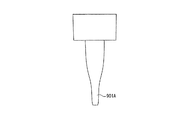
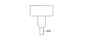
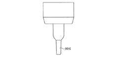
医療用容器に設けられたオス型コネクタは、通常、液状物が流出する管状部を有するが、その形状や寸法に関して標準となる規格は存在せず、医療用容器やオス型コネクタの製造メーカごとに異なる。図46A〜図46Iは、各製造メーカが採用している従来のオス型コネクタの管状部901A〜901Iを示した側面図である。これらに示されるように、オス型コネクタの管状部の外周面の形状、外径、長さなどに関する規格はメーカごとに異なっている。   A male connector provided in a medical container usually has a tubular part through which a liquid material flows out, but there is no standard for its shape and dimensions, and each manufacturer of medical containers and male connectors Different. 46A to 46I are side views showing tubular portions 901A to 901I of a conventional male connector adopted by each manufacturer. As shown in these figures, the standards regarding the shape, outer diameter, length, etc. of the outer peripheral surface of the tubular portion of the male connector differ from manufacturer to manufacturer.

経腸栄養を行う施設(例えば医療機関)においては、従来、経腸栄養剤が充填される容器及び経腸栄養セットは再利用される場合が多く、その場合には、容器と経腸栄養セットとを接続した状態で洗浄、消毒、経腸栄養剤の充填が行われていた。ところが、近年、感染防止の観点から、経腸栄養剤を使い捨ての容器に充填した状態で販売されるプレフィルド型栄養剤が普及しつつある。プレフィルド型栄養剤の普及にともない、容器と経腸栄養セットとが別体として取り扱われる機会が増え、上記のように容器のオス型コネクタの管状部に関して各種の規格が存在することに起因する、容器のオス型コネクタと経腸栄養セットのメス型コネクタとの適合不良(接続不良)の問題が顕在化してきた。   In facilities for enteral nutrition (for example, medical institutions), containers filled with enteral nutrients and enteral nutrition sets are often reused. In such cases, the container and enteral nutrition set are often used. In the connected state, cleaning, disinfection and filling with enteral nutrients were performed. However, in recent years, from the viewpoint of preventing infection, prefilled nutrients sold in a state where enteral nutrients are filled in disposable containers are becoming widespread. With the spread of prefilled type nutrients, the chance that the container and enteral nutrition set are handled as separate bodies is increased, and due to the existence of various standards regarding the tubular part of the male connector of the container as described above, The problem of poor fitting (connection failure) between the male connector of the container and the female connector of the enteral nutrition set has become apparent.

各種のオス型コネクタに接続可能な従来の汎用のメス型コネクタとしては、図47Aに示すように、形状や寸法が異なる各種のオス型コネクタの管状部901に接続できるように、チューブ903の一端に接続された弾性を有する円筒状のゴム管902が用いられていた。図47Bに示すようにゴム管902を管状部901の外周面上に被せるように矢印910の向きに挿入し、図47Cに示すようにゴム管902と管状部901とを接続する。ゴム管902は、管状部901の外周面のテーパ形状に応じて伸び且つ変形し、その弾性回復力により管状部901の外周面に密着する。   As a conventional general-purpose female connector that can be connected to various male connectors, as shown in FIG. 47A, one end of a tube 903 is connected so that it can be connected to tubular portions 901 of various male connectors having different shapes and dimensions. A cylindrical rubber tube 902 having elasticity connected to the tube was used. 47B, the rubber tube 902 is inserted in the direction of the arrow 910 so as to cover the outer peripheral surface of the tubular portion 901, and the rubber tube 902 and the tubular portion 901 are connected as shown in FIG. 47C. The rubber tube 902 extends and deforms according to the taper shape of the outer peripheral surface of the tubular portion 901, and is in close contact with the outer peripheral surface of the tubular portion 901 by its elastic recovery force.

特開平11−28244号公報Japanese Patent Laid-Open No. 11-28244

しかしながら、図47Aに示したゴム管902からなる従来の汎用のメス型コネクタは、管状部901とゴム管902との間に発生する摩擦力のために、管状部901にゴム管902を接続する作業がしづらいという問題を有していた。接続作業では、ゴム管902の外周面を2本の指で把持する。図47Bにおいて、管状部901に被さっているゴム管902の領域902aを把持すると、把持力が管状部901とゴム管902との間の摩擦力を増大させるので、管状部901に対してゴム管902を移動させるのが困難である。図47Bにおいて、管状部901に被さっていないゴム管902の領域902b又はチューブ903を把持すると、矢印910の向きの力によってゴム管902が容易に座屈変形してしまい、やはり管状部901に対してゴム管902を移動させるのが困難である。   However, the conventional general-purpose female connector including the rubber tube 902 shown in FIG. 47A connects the rubber tube 902 to the tubular portion 901 due to the frictional force generated between the tubular portion 901 and the rubber tube 902. The problem was that it was difficult to work. In the connection work, the outer peripheral surface of the rubber tube 902 is gripped with two fingers. In FIG. 47B, when the region 902a of the rubber tube 902 covering the tubular portion 901 is gripped, the gripping force increases the frictional force between the tubular portion 901 and the rubber tube 902. It is difficult to move 902. In FIG. 47B, when the region 902b of the rubber tube 902 or the tube 903 that does not cover the tubular portion 901 is gripped, the rubber tube 902 is easily buckled and deformed by the force in the direction of the arrow 910. Thus, it is difficult to move the rubber tube 902.

ゴム管902が容易に伸びるようにその柔軟性を高めると、ゴム管902が更に座屈変形しやすくなり、接続作業は却って困難になる。また、ゴム管902の内径を大きくすると、管状部901とゴム管902との間の摩擦力を小さくすることができるので、管状部901とゴム管902との接続作業は容易になる。ところが、この場合、管状部901に装着されたゴム管902が容易に脱落してしまったり、管状部901とゴム管902との間から液状物が漏れたりするという新たな問題が発生する。   When the flexibility of the rubber tube 902 is increased so that the rubber tube 902 can be easily extended, the rubber tube 902 is more easily buckled and deformed, and the connecting operation becomes difficult. Further, when the inner diameter of the rubber tube 902 is increased, the frictional force between the tubular portion 901 and the rubber tube 902 can be reduced, so that the connection work between the tubular portion 901 and the rubber tube 902 is facilitated. However, in this case, there arises a new problem that the rubber tube 902 attached to the tubular portion 901 easily falls off or a liquid material leaks between the tubular portion 901 and the rubber tube 902.

また、オス型コネクタの管状部901の外周面の形状や寸法によっては、ゴム管902に管状部901を挿入するのに手間取る場合があるという問題がある。   Further, depending on the shape and dimensions of the outer peripheral surface of the tubular portion 901 of the male connector, there is a problem that it may take time to insert the tubular portion 901 into the rubber tube 902.

上記の問題は、PEGチューブや静脈栄養療法で使用される輸液ラインを構成するチューブを接続する場合にも同様に発生していた。   The above-mentioned problem has occurred in the same way when connecting a PEG tube or a tube constituting an infusion line used in parenteral nutrition therapy.

本発明は、上記の従来の問題を解決し、形状や寸法が異なる各種のオス型コネクタに接続することができ、且つ、オス型コネクタへの接続作業が容易であるメス型コネクタ及び接続具を提供することを目的とする。   The present invention provides a female connector and a connector that solve the above-described conventional problems, can be connected to various male connectors having different shapes and dimensions, and can be easily connected to the male connector. The purpose is to provide.

本発明のメス型コネクタは、液状物が流出する管状部を有するオス型コネクタに接続されるメス型コネクタであって、前記管状部の外周面に装着されるアダプタと、前記アダプタに外装されるハンドルとを備える。前記アダプタは、その一端に開口を有する筒状部を有し、前記筒状部は前記開口から前記管状部が挿入される挿入部を含み、前記挿入部は可撓性及び弾性を有する。前記ハンドルは、前記アダプタの前記挿入部よりも高い剛性を有する。前記アダプタの中心軸方向に沿って前記アダプタの前記開口とは反対側の端から前記開口側の端に向かって前記ハンドルが前記アダプタに対して相対的に移動できる範囲を制限する移動制限手段が設けられている。前記ハンドルは、前記移動制限手段よりも前記オス型コネクタ側に突出した鍔部を備える。前記鍔部の前記ハンドルの中心軸に対向する内周面は、周方向に延在する係合壁と、前記係合壁の前記オス型コネクタとは反対側に設けられた凹部と、前記凹部に対して周方向のいずれか一方の側に前記凹部に隣接して設けられた凸部とを備える。前記係合壁が前記オス型コネクタと係合可能であることを特徴とする。   The female connector according to the present invention is a female connector connected to a male connector having a tubular portion through which a liquid material flows out, and is mounted on an outer peripheral surface of the tubular portion, and is mounted on the adapter. And a handle. The adapter includes a cylindrical portion having an opening at one end thereof, and the cylindrical portion includes an insertion portion into which the tubular portion is inserted from the opening, and the insertion portion has flexibility and elasticity. The handle has higher rigidity than the insertion portion of the adapter. A movement restricting means for restricting a range in which the handle can move relative to the adapter from an end opposite to the opening of the adapter along the central axis direction of the adapter toward the end of the opening. Is provided. The handle includes a flange that protrudes toward the male connector than the movement restricting means. The inner peripheral surface of the collar portion facing the central axis of the handle has an engagement wall extending in the circumferential direction, a recess provided on the opposite side of the engagement wall from the male connector, and the recess And a convex portion provided adjacent to the concave portion on either side in the circumferential direction. The engagement wall is engageable with the male connector.

本発明の接続具は、液状物が流出する管状部を有するオス型コネクタと、前記オス型コネクタに接続されるメス型コネクタとからなる接続具であって、前記メス型コネクタが上記の本発明のメス型コネクタであることを特徴とする。   The connector of the present invention is a connector composed of a male connector having a tubular portion through which a liquid material flows out and a female connector connected to the male connector, and the female connector is the above-described present invention. It is characterized by being a female connector.

本発明によれば、アダプタの挿入部が可撓性及び弾性を有するので、メス型コネクタを、形状や寸法が異なる各種のオス型コネクタに接続することができる。しかも、アダプタの挿入部よりも高い剛性を有するハンドルを介して、オス型コネクタに近づく向きの力をアダプタに印加することができるので、メス型コネクタとオス型コネクタとの接続作業が容易である。   According to the present invention, since the insertion portion of the adapter has flexibility and elasticity, the female connector can be connected to various male connectors having different shapes and dimensions. Moreover, since a force approaching the male connector can be applied to the adapter via the handle having higher rigidity than the insertion portion of the adapter, the connection work between the female connector and the male connector is easy. .

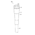
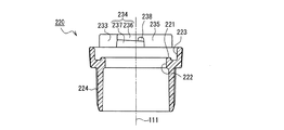
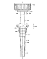
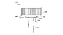
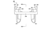
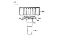
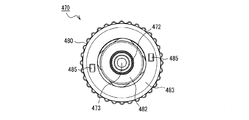
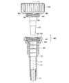
図1Aは本発明の実施の形態1に係るメス型コネクタの概略構成を示した斜視図である。FIG. 1A is a perspective view showing a schematic configuration of a female connector according to Embodiment 1 of the present invention. 図1Bは図1Aに示したメス型コネクタの断面図である。1B is a cross-sectional view of the female connector shown in FIG. 1A. 図2Aは本発明の実施の形態1に係るメス型コネクタを構成するアダプタの概略構成を示した斜視図である。FIG. 2A is a perspective view showing a schematic configuration of an adapter constituting the female connector according to Embodiment 1 of the present invention. 図2Bは図2Aに示したアダプタの断面図である。2B is a cross-sectional view of the adapter shown in FIG. 2A. 図3Aは本発明の実施の形態1に係るメス型コネクタを構成するハンドルの概略構成を示した斜視図である。FIG. 3A is a perspective view showing a schematic configuration of a handle constituting the female connector according to Embodiment 1 of the present invention. 図3Bは図3Aに示したハンドルの断面図である。3B is a cross-sectional view of the handle shown in FIG. 3A. 図4は、医療用容器及びオス型コネクタの一例の概略構成を示した分解図である。FIG. 4 is an exploded view showing a schematic configuration of an example of a medical container and a male connector. 図5Aは、オス型コネクタに本発明の実施の形態1に係るメス型コネクタを接続する方法を示した断面図であり、接続前の状態を示している。FIG. 5A is a cross-sectional view showing a method of connecting the female connector according to Embodiment 1 of the present invention to the male connector, and shows a state before connection. 図5Bは、オス型コネクタに本発明の実施の形態1に係るメス型コネクタを接続する方法を示した断面図であり、接続後の状態を示している。FIG. 5B is a cross-sectional view showing a method of connecting the female connector according to Embodiment 1 of the present invention to the male connector, and shows a state after the connection. 図6は、外径が小さな管状部を有するオス型コネクタに本発明の実施の形態1に係るメス型コネクタを接続した状態を示した断面図である。FIG. 6 is a cross-sectional view showing a state where the female connector according to Embodiment 1 of the present invention is connected to a male connector having a tubular portion with a small outer diameter. 図7Aは本発明の実施の形態1に係るメス型コネクタを構成する別のアダプタの概略構成を示した斜視図である。FIG. 7A is a perspective view showing a schematic configuration of another adapter constituting the female connector according to Embodiment 1 of the present invention. 図7Bは図7Aに示したアダプタの断面図である。FIG. 7B is a cross-sectional view of the adapter shown in FIG. 7A. 図8は本発明の実施の形態1に係るメス型コネクタを構成する更に別のアダプタの概略構成を示した斜視図である。FIG. 8 is a perspective view showing a schematic configuration of still another adapter constituting the female connector according to Embodiment 1 of the present invention. 図9Aは本発明の実施の形態1において、ハンドルを保持する機構が設けられたアダプタの概略構成を示した斜視図である。FIG. 9A is a perspective view showing a schematic configuration of an adapter provided with a mechanism for holding a handle in Embodiment 1 of the present invention. 図9Bは図9Aに示したアダプタに設けられた、ハンドルを保持する機構の作用を示した断面図である。FIG. 9B is a cross-sectional view showing the action of the mechanism for holding the handle provided in the adapter shown in FIG. 9A. 図10Aは本発明の実施の形態1において、ハンドルを保持する別の機構が設けられたアダプタの概略構成を示した斜視図である。FIG. 10A is a perspective view showing a schematic configuration of an adapter provided with another mechanism for holding a handle in Embodiment 1 of the present invention. 図10Bは図10Aの10B−10B線でのアダプタの矢視断面図である。10B is a cross-sectional view of the adapter taken along line 10B-10B in FIG. 10A. 図11は本発明の実施の形態1において、ハンドルを保持する別の機構が設けられたメス型コネクタの概略構成を示した斜視図である。FIG. 11 is a perspective view showing a schematic configuration of a female connector provided with another mechanism for holding a handle in Embodiment 1 of the present invention. 図12は本発明の実施の形態1において、ハンドルを保持する別の機構が設けられたメス型コネクタの概略構成を示した斜視図である。FIG. 12 is a perspective view showing a schematic configuration of the female connector provided with another mechanism for holding the handle in the first embodiment of the present invention. 図13Aは本発明の実施の形態1に係るメス型コネクタを構成する別のハンドルの概略構成を示した斜視図である。FIG. 13A is a perspective view showing a schematic configuration of another handle constituting the female connector according to Embodiment 1 of the present invention. 図13Bは図13Aに示したハンドルの断面図である。13B is a cross-sectional view of the handle shown in FIG. 13A. 図14Aは本発明の実施の形態1に係るメス型コネクタを構成する更に別のハンドルの概略構成を示した斜視図である。FIG. 14A is a perspective view showing a schematic configuration of still another handle constituting the female connector according to Embodiment 1 of the present invention. 図14Bは本発明の実施の形態1に係るメス型コネクタを構成する更に別のハンドルの概略構成を示した斜視図である。FIG. 14B is a perspective view showing a schematic configuration of still another handle constituting the female connector according to Embodiment 1 of the present invention. 図15Aは本発明の実施の形態1に係るメス型コネクタを構成する更に別のハンドルの概略構成を示した斜視図である。FIG. 15A is a perspective view showing a schematic configuration of still another handle constituting the female connector according to Embodiment 1 of the present invention. 図15Bは図15Aに示したハンドルの断面図である。15B is a cross-sectional view of the handle shown in FIG. 15A. 図16Aは本発明の実施の形態1に係るメス型コネクタを構成する更に別のハンドルの概略構成を示した斜視図である。FIG. 16A is a perspective view showing a schematic configuration of still another handle constituting the female connector according to Embodiment 1 of the present invention. 図16Bは図16Aに示したハンドルの断面図である。FIG. 16B is a cross-sectional view of the handle shown in FIG. 16A. 図17は本発明の実施の形態1に係るメス型コネクタを構成する更に別のハンドルの概略構成を示した斜視図である。FIG. 17 is a perspective view showing a schematic configuration of still another handle constituting the female connector according to Embodiment 1 of the present invention. 図18Aは本発明の実施の形態1に係るメス型コネクタを構成する更に別のハンドルの概略構成を示した斜視図である。FIG. 18A is a perspective view showing a schematic configuration of still another handle constituting the female connector according to Embodiment 1 of the present invention. 図18Bは図18Aに示したハンドルの平面図である。18B is a plan view of the handle shown in FIG. 18A. 図19Aは本発明の実施の形態1に係るメス型コネクタを構成する更に別のハンドルの概略構成を示した斜視図である。FIG. 19A is a perspective view showing a schematic configuration of still another handle constituting the female connector according to Embodiment 1 of the present invention. 図19Bは図19Aに示したハンドルの平面図である。FIG. 19B is a plan view of the handle shown in FIG. 19A. 図20Aは本発明の実施の形態1に係る別のメス型コネクタの概略構成を示した斜視図である。FIG. 20A is a perspective view showing a schematic configuration of another female connector according to Embodiment 1 of the present invention. 図20Bは図20Aに示したメス型コネクタの断面図である。20B is a cross-sectional view of the female connector shown in FIG. 20A. 図21Aは本発明の実施の形態1に係る別のメス型コネクタを構成するアダプタの概略構成を示した斜視図である。FIG. 21A is a perspective view showing a schematic configuration of an adapter constituting another female connector according to Embodiment 1 of the present invention. 図21Bは図21Aに示したアダプタの断面図である。FIG. 21B is a cross-sectional view of the adapter shown in FIG. 21A. 図22Aは本発明の実施の形態1に係る別のメス型コネクタを構成するハンドルの概略構成を示した斜視図である。FIG. 22A is a perspective view showing a schematic configuration of a handle constituting another female connector according to Embodiment 1 of the present invention. 図22Bは図22Aに示したハンドルの断面図である。22B is a cross-sectional view of the handle shown in FIG. 22A. 図23Aは本発明の実施の形態1に係る更に別のメス型コネクタの概略構成を示した斜視図である。FIG. 23A is a perspective view showing a schematic configuration of still another female connector according to Embodiment 1 of the present invention. 図23Bは図23Aに示したメス型コネクタの断面図である。23B is a cross-sectional view of the female connector shown in FIG. 23A. 図24は本発明の実施の形態2に係るオス型コネクタの概略構成を示した斜視図である。FIG. 24 is a perspective view showing a schematic configuration of a male connector according to Embodiment 2 of the present invention. 図25Aは本発明の実施の形態2に係るオス型コネクタの概略構成を示した正面図である。FIG. 25A is a front view showing a schematic configuration of the male connector according to Embodiment 2 of the present invention. 図25Bは本発明の実施の形態2に係るオス型コネクタの概略構成を示した下面図である。FIG. 25B is a bottom view showing a schematic configuration of the male connector according to Embodiment 2 of the present invention. 図26は本発明の実施の形態2に係るメス型コネクタを構成するハンドルの概略構成を示した斜視図である。FIG. 26 is a perspective view showing a schematic configuration of a handle constituting the female connector according to Embodiment 2 of the present invention. 図27Aは本発明の実施の形態2に係るメス型コネクタを構成するハンドルの概略構成を示した平面図である。FIG. 27A is a plan view showing a schematic configuration of a handle constituting the female connector according to Embodiment 2 of the present invention. 図27Bは本発明の実施の形態2に係るメス型コネクタを構成するハンドルの概略構成を示した正面図である。FIG. 27B is a front view showing a schematic configuration of the handle constituting the female connector according to Embodiment 2 of the present invention. 図27Cは本発明の実施の形態2に係るメス型コネクタを構成するハンドルの概略構成を示した右側面図である。FIG. 27C is a right side view showing a schematic configuration of the handle constituting the female connector according to Embodiment 2 of the present invention. 図28Aは図27Bの28A−28A線でのハンドルの矢視断面図である。28A is a cross-sectional view of the handle taken along line 28A-28A in FIG. 27B. 図28Bは図27Cの28B−28B線でのハンドルの矢視断面図である。28B is a cross-sectional view of the handle taken along line 28B-28B in FIG. 27C. 図29は、本発明の実施の形態2において、オス型コネクタにメス型コネクタを接続する方法を示した断面図である。FIG. 29 is a cross-sectional view showing a method for connecting a female connector to a male connector in Embodiment 2 of the present invention. 図30は本発明の実施の形態2に係るメス型コネクタ及びオス型コネクタが接続された状態を示した斜視図である。FIG. 30 is a perspective view showing a state where the female connector and the male connector according to Embodiment 2 of the present invention are connected. 図31は本発明の実施の形態3に係るオス型コネクタの概略構成を示した斜視図である。FIG. 31 is a perspective view showing a schematic configuration of a male connector according to Embodiment 3 of the present invention. 図32Aは本発明の実施の形態3に係るオス型コネクタの概略構成を示した正面図である。FIG. 32A is a front view showing a schematic configuration of the male connector according to Embodiment 3 of the present invention. 図32Bは本発明の実施の形態3に係るオス型コネクタの概略構成を示した下面図である。FIG. 32B is a bottom view showing a schematic configuration of the male connector according to Embodiment 3 of the present invention. 図33は本発明の実施の形態3に係るメス型コネクタを構成するハンドルの概略構成を示した斜視図である。FIG. 33 is a perspective view showing a schematic configuration of a handle constituting the female connector according to Embodiment 3 of the present invention. 図34Aは本発明の実施の形態3に係るメス型コネクタを構成するハンドルの概略構成を示した平面図である。FIG. 34A is a plan view showing a schematic configuration of a handle constituting the female connector according to Embodiment 3 of the present invention. 図34Bは本発明の実施の形態3に係るメス型コネクタを構成するハンドルの概略構成を示した正面図である。FIG. 34B is a front view showing a schematic configuration of the handle constituting the female connector according to Embodiment 3 of the present invention. 図35Aは図34Aの35A−35A線でのハンドルの矢視断面図である。35A is a cross-sectional view of the handle taken along the line 35A-35A in FIG. 34A. 図35Bは図34Bの35B−35B線でのハンドルの矢視断面図である。35B is a cross-sectional view of the handle taken along line 35B-35B in FIG. 34B. 図36は、本発明の実施の形態3において、オス型コネクタにメス型コネクタを接続する方法を示した断面図である。FIG. 36 is a cross-sectional view showing a method for connecting a female connector to a male connector in Embodiment 3 of the present invention. 図37は本発明の実施の形態3に係るメス型コネクタ及びオス型コネクタが接続された状態を示した斜視図である。FIG. 37 is a perspective view showing a state where the female connector and the male connector according to Embodiment 3 of the present invention are connected. 図38は本発明の実施の形態4に係るオス型コネクタの概略構成を示した斜視図である。FIG. 38 is a perspective view showing a schematic configuration of a male connector according to Embodiment 4 of the present invention. 図39Aは本発明の実施の形態4に係るオス型コネクタの概略構成を示した正面図である。FIG. 39A is a front view showing a schematic configuration of the male connector according to Embodiment 4 of the present invention. 図39Bは本発明の実施の形態4に係るオス型コネクタの概略構成を示した下面図である。FIG. 39B is a bottom view showing a schematic configuration of the male connector according to Embodiment 4 of the present invention. 図40は本発明の実施の形態4に係るメス型コネクタを構成するハンドルの概略構成を示した斜視図である。FIG. 40 is a perspective view showing a schematic configuration of a handle constituting the female connector according to Embodiment 4 of the present invention. 図41は本発明の実施の形態4に係るメス型コネクタを構成するハンドルの中心軸に沿った断面図である。FIG. 41 is a cross-sectional view along the central axis of the handle constituting the female connector according to Embodiment 4 of the present invention. 図42は、本発明の実施の形態4において、オス型コネクタにメス型コネクタを接続する方法を示した断面図である。FIG. 42 is a cross-sectional view showing a method for connecting a female connector to a male connector in Embodiment 4 of the present invention. 図43は本発明の実施の形態4に係るメス型コネクタ及びオス型コネクタが接続された状態を示した斜視図である。FIG. 43 is a perspective view showing a state where the female connector and the male connector according to Embodiment 4 of the present invention are connected. 図44は医療用容器の別の例の概略構成を示した図である。FIG. 44 is a diagram showing a schematic configuration of another example of the medical container. 図45Aは図44の医療用容器に使用されるオス型コネクタ(ポート)の概略斜視図である。45A is a schematic perspective view of a male connector (port) used in the medical container of FIG. 44. FIG. 図45Bは図45Aに示したオス型コネクタ(ポート)の正面図である。45B is a front view of the male connector (port) shown in FIG. 45A. 図45Cは図45Aに示したオス型コネクタ(ポート)の右側面図である。45C is a right side view of the male connector (port) shown in FIG. 45A. 図46Aは、従来のオス型コネクタの管状部の一例を示した側面図である。FIG. 46A is a side view showing an example of a tubular portion of a conventional male connector. 図46Bは、従来のオス型コネクタの管状部の別の例を示した側面図である。FIG. 46B is a side view showing another example of the tubular portion of the conventional male connector. 図46Cは、従来のオス型コネクタの管状部の更に別の例を示した側面図である。FIG. 46C is a side view showing still another example of the tubular portion of the conventional male connector. 図46Dは、従来のオス型コネクタの管状部の更に別の例を示した側面図である。FIG. 46D is a side view showing still another example of the tubular portion of the conventional male connector. 図46Eは、従来のオス型コネクタの管状部の更に別の例を示した側面図である。FIG. 46E is a side view showing still another example of the tubular portion of the conventional male connector. 図46Fは、従来のオス型コネクタの管状部の更に別の例を示した側面図である。FIG. 46F is a side view showing still another example of the tubular portion of the conventional male connector. 図46Gは、従来のオス型コネクタの管状部の更に別の例を示した側面図である。FIG. 46G is a side view showing still another example of the tubular portion of the conventional male connector. 図46Hは、従来のオス型コネクタの管状部の更に別の例を示した側面図である。FIG. 46H is a side view showing still another example of the tubular portion of the conventional male connector. 図46Iは、従来のオス型コネクタの管状部の更に別の例を示した側面図である。FIG. 46I is a side view showing still another example of the tubular portion of the conventional male connector. 図47Aは、オス型コネクタに従来の汎用型のメス型コネクタを接続する方法の一例を示した断面図であり、接続前の状態を示している。FIG. 47A is a cross-sectional view showing an example of a method of connecting a conventional general-purpose female connector to a male connector, and shows a state before connection. 図47Bは、オス型コネクタに従来の汎用型のメス型コネクタを接続する方法の一例を示した断面図であり、接続中の状態を示している。FIG. 47B is a cross-sectional view showing an example of a method for connecting a conventional general-purpose female connector to a male connector, and shows a state during connection. 図47Cは、オス型コネクタに従来の汎用型のメス型コネクタを接続する方法の一例を示した断面図であり、接続後の状態を示している。FIG. 47C is a cross-sectional view showing an example of a method of connecting a conventional general-purpose female connector to a male connector, and shows a state after connection.

本発明のメス型コネクタは、液状物が流出する管状部を有するオス型コネクタに接続されるメス型コネクタであって、前記管状部の外周面に装着されるアダプタと、前記アダプタに外装されるハンドルとを備える。前記アダプタは、その一端に開口を有する筒状部を有し、前記筒状部は前記開口から前記管状部が挿入される挿入部を含み、前記挿入部は可撓性及び弾性を有する。前記ハンドルは、前記アダプタの前記挿入部よりも高い剛性を有する。前記アダプタの中心軸方向に沿って前記アダプタの前記開口とは反対側の端から前記開口側の端に向かって前記ハンドルが前記アダプタに対して相対的に移動できる範囲を制限する移動制限手段が設けられている。   The female connector according to the present invention is a female connector connected to a male connector having a tubular portion through which a liquid material flows out, and is mounted on an outer peripheral surface of the tubular portion, and is mounted on the adapter. And a handle. The adapter includes a cylindrical portion having an opening at one end thereof, and the cylindrical portion includes an insertion portion into which the tubular portion is inserted from the opening, and the insertion portion has flexibility and elasticity. The handle has higher rigidity than the insertion portion of the adapter. A movement restricting means for restricting a range in which the handle can move relative to the adapter from an end opposite to the opening of the adapter along the central axis direction of the adapter toward the end of the opening. Is provided.

本発明の上記のメス型コネクタにおいて、前記移動制限手段が、前記筒状部の外周面より外方向に突出するように前記アダプタの前記筒状部の前記開口側の端又はその近傍に設けられたフランジ部と、前記フランジ部の前記開口とは反対側の面を保持するように前記ハンドルに設けられたフランジ保持部とを含んでいても良い。筒状部の開口側の端又はその近傍にフランジ部が設けられているので、筒状部の開口の周縁の剛性が向上する。従って、アダプタの筒状部の開口にオス型コネクタの管状部を挿入する際に、筒状部が変形しにくい。また、ハンドルのフランジ保持部で筒状部に設けられたフランジ部を保持しながら管状部を筒状部に挿入することができるので、筒状部の座屈変形を防止できる。よって、この好ましい形態によれば、アダプタへの管状部の挿入作業が一層容易になる。   In the female connector according to the present invention, the movement restricting means is provided at an end of the cylindrical portion of the adapter on the opening side or in the vicinity thereof so as to protrude outward from the outer peripheral surface of the cylindrical portion. And a flange holding portion provided on the handle so as to hold a surface of the flange portion opposite to the opening. Since the flange portion is provided at the opening side end of the tubular portion or in the vicinity thereof, the rigidity of the peripheral edge of the opening of the tubular portion is improved. Therefore, when the tubular portion of the male connector is inserted into the opening of the tubular portion of the adapter, the tubular portion is not easily deformed. Further, since the tubular portion can be inserted into the tubular portion while holding the flange portion provided on the tubular portion with the flange retaining portion of the handle, the buckling deformation of the tubular portion can be prevented. Therefore, according to this preferable embodiment, the operation of inserting the tubular portion into the adapter is further facilitated.

本発明の上記のメス型コネクタにおいて、前記移動制限手段は、更に、前記アダプタの中心軸方向に沿って前記アダプタの前記開口側の端から前記開口とは反対側の端に向かって前記ハンドルが前記アダプタに対して相対的に移動できる範囲を制限しても良い。これにより、ハンドルはアダプタに常に保持されるので、ハンドルがアダプタから遠く離れた位置に移動してしまうのを防止できる。従って、オス型コネクタにメス型コネクタを接続する際の作業性が向上し、また、経腸栄養セットやPEGチューブ等の製造工程においてハンドルが意図せずに破損するのを防止できる。   In the female connector according to the present invention, the movement restricting means further includes the handle extending from the opening-side end of the adapter toward the end opposite to the opening along the central axis direction of the adapter. You may restrict | limit the range which can move relatively with respect to the said adapter. Thereby, since the handle is always held by the adapter, it is possible to prevent the handle from moving to a position far away from the adapter. Therefore, the workability at the time of connecting the female connector to the male connector is improved, and the handle can be prevented from being unintentionally damaged in the manufacturing process of the enteral nutrition set, the PEG tube and the like.

この場合、前記移動制限手段が、前記筒状部及びハンドルのうちの一方の他方に対向する面に設けられた、周方向に沿った環状の溝と、前記溝に嵌入するように前記筒状部及びハンドルのうちの他方に設けられた嵌入部とを含むことが好ましい。これにより、簡単且つ低コストに移動制限手段を実現することができる。   In this case, the movement restricting means is provided on a surface facing the other one of the tubular portion and the handle, and an annular groove along the circumferential direction, and the tubular shape so as to fit into the groove. It is preferable that the insertion part provided in the other of a part and a handle | steering_wheel is included. Thereby, a movement restricting means can be realized easily and at low cost.

この場合、前記アダプタの中心軸方向において、前記溝の幅をW1、前記嵌入部の幅をW2としたとき、1.0≦W1/W2≦1.5を満足することが好ましい。W1/W2がこの下限より小さいと、溝内に嵌入部を嵌入させることが困難である。W1/W2がこの上限より大きいと、アダプタに対するハンドルの相対的な可動範囲が大きくなるので、アダプタの中心軸に対してハンドルの中心軸が傾きやすくなり、傾いたハンドルの向きを修正するなどの煩雑な作業を強いられたり、溝から嵌入部が外れたりすることがある。   In this case, it is preferable that 1.0 ≦ W1 / W2 ≦ 1.5 is satisfied when the width of the groove is W1 and the width of the fitting portion is W2 in the central axis direction of the adapter. If W1 / W2 is smaller than this lower limit, it is difficult to insert the insertion portion into the groove. If W1 / W2 is larger than this upper limit, the range of relative movement of the handle with respect to the adapter increases, so the center axis of the handle tends to tilt with respect to the center axis of the adapter, and the orientation of the tilted handle is corrected. A complicated work may be forced, or the fitting part may come off from the groove.

本発明の上記のメス型コネクタにおいて、前記移動制限手段が、前記アダプタと前記ハンドルとを固着する固着部を含んでいても良い。これによっても、アダプタの中心軸方向に沿ってハンドルがアダプタに対して相対的に移動できる範囲を制限する移動制限手段を簡単且つ低コストに実現することができる。   In the above female connector of the present invention, the movement restricting means may include a fixing portion for fixing the adapter and the handle. This also makes it possible to easily and inexpensively implement a movement restricting means for restricting the range in which the handle can move relative to the adapter along the center axis direction of the adapter.

本発明の上記のメス型コネクタにおいて、前記アダプタの前記挿入部の内周面は、その内径が前記開口に近づくにしたがって大きくなるテーパ面を有していることが好ましい。これにより、オス型コネクタの管状部の形状や寸法等が異なっても、オス型コネクタの管状部の外周面の少なくとも一部とアダプタの挿入部の内周面の少なくとも一部とを密着させることができるので、メス型コネクタを各種のオス型コネクタに液状物の漏れなく確実に接続することができる。   In the female connector according to the present invention, it is preferable that the inner peripheral surface of the insertion portion of the adapter has a tapered surface whose inner diameter increases as the opening approaches. Thereby, even if the shape and size of the tubular portion of the male connector are different, at least a part of the outer peripheral surface of the tubular portion of the male connector and at least a part of the inner peripheral surface of the insertion portion of the adapter are brought into close contact with each other. Therefore, the female connector can be reliably connected to various male connectors without leakage of liquid material.

本発明の上記のメス型コネクタにおいて、前記アダプタの前記挿入部の内周面に、周方向に沿った環状の突起が形成されていることが好ましい。これにより、オス型コネクタの管状部の形状や寸法等に応じて管状部の外周面に挿入部の環状の突起を適宜変形させて密着させることができる。従って、メス型コネクタを各種のオス型コネクタに液状物の漏れなく確実に接続することができる。   In the female connector according to the present invention, it is preferable that an annular protrusion along the circumferential direction is formed on the inner peripheral surface of the insertion portion of the adapter. Thereby, according to the shape, dimension, etc. of the tubular part of the male connector, the annular projection of the insertion part can be appropriately deformed and brought into close contact with the outer peripheral surface of the tubular part. Therefore, the female connector can be reliably connected to various male connectors without leakage of the liquid material.

本発明の上記のメス型コネクタにおいて、前記アダプタの前記挿入部の内周面に、周方向に沿った環状の段差が形成されており、前記段差に対して前記開口側での前記挿入部の内径が、前記段差に対して前記開口とは反対側での前記挿入部の内径より大きくなるように、前記段差は前記挿入部の内径を階段状に変化させることが好ましい。これにより、オス型コネクタの管状部が太い場合には、管状部はアダプタの挿入部の段差より開口側の部分と密着し、オス型コネクタの管状部が細い場合には、管状部はアダプタの挿入部の段差より開口とは反対側の部分と密着する。従って、メス型コネクタを各種の太さを有する管状部に液状物の漏れなく確実に接続することができる。   In the female connector of the present invention, an annular step along the circumferential direction is formed on the inner peripheral surface of the insertion portion of the adapter, and the insertion portion on the opening side with respect to the step is formed. The step preferably changes the inner diameter of the insertion portion in a stepped manner so that the inner diameter is larger than the inner diameter of the insertion portion on the side opposite to the opening with respect to the step. Thereby, when the tubular portion of the male connector is thick, the tubular portion is in close contact with the portion on the opening side of the step of the insertion portion of the adapter, and when the tubular portion of the male connector is thin, the tubular portion is It is in close contact with the portion opposite to the opening from the step of the insertion portion. Accordingly, the female connector can be reliably connected to the tubular portion having various thicknesses without leakage of the liquid material.

本発明の上記のメス型コネクタにおいて、前記アダプタに、前記ハンドルを保持する保持機構が設けられていることが好ましい。これにより、ハンドルがアダプタから遠く離れた位置に移動してしまうのを防止できる。従って、オス型コネクタにメス型コネクタを接続する際の作業性が向上し、また、経腸栄養セットやPEGチューブ等の製造工程においてハンドルが意図せずに破損するのを防止できる。   In the female connector according to the present invention, it is preferable that the adapter is provided with a holding mechanism for holding the handle. This can prevent the handle from moving to a position far away from the adapter. Therefore, the workability at the time of connecting the female connector to the male connector is improved, and the handle can be prevented from being unintentionally damaged in the manufacturing process of the enteral nutrition set, the PEG tube and the like.

上記において、前記保持機構が、前記ハンドルの前記オス型コネクタとは反対側の端に当接するように前記アダプタの前記筒状部の外周面より外方向に突出した係止突起であっても良い。あるいは、前記保持機構が、前記ハンドルの内周面に当接するように前記アダプタの前記筒状部の外周面より外方向に突出した接触突起であっても良い。いずれの場合も、簡単な構成で保持機構を実現できる。また、保持機構をアダプタに一体成形にて形成することができるので、安価且つ効率的に保持機構付きのアダプタを作成できる。   In the above, the holding mechanism may be a locking protrusion that protrudes outward from the outer peripheral surface of the cylindrical portion of the adapter so as to contact the end of the handle opposite to the male connector. . Alternatively, the holding mechanism may be a contact protrusion that protrudes outward from the outer peripheral surface of the cylindrical portion of the adapter so as to contact the inner peripheral surface of the handle. In either case, the holding mechanism can be realized with a simple configuration. In addition, since the holding mechanism can be formed integrally with the adapter, an adapter with the holding mechanism can be created inexpensively and efficiently.

本発明の上記のメス型コネクタにおいて、前記アダプタの前記開口とは反対側の端に接続されたチューブに、前記ハンドルを保持する保持機構が設けられていても良い。あるいは、前記アダプタの前記開口とは反対側の端に接続されたチューブ又は前記アダプタに前記ハンドルが保持されるように前記ハンドルに保持機構が設けられていても良い。いずれの場合も、ハンドルがアダプタから遠く離れた位置に移動してしまうのを防止できる。従って、オス型コネクタにメス型コネクタを接続する際の作業性が向上し、また、経腸栄養セットやPEGチューブ等の製造工程においてハンドルが意図せずに破損するのを防止できる。   In the female connector of the present invention, a holding mechanism for holding the handle may be provided in a tube connected to an end of the adapter opposite to the opening. Alternatively, a holding mechanism may be provided on the handle so that the handle is held by a tube connected to the end of the adapter opposite to the opening or the adapter. In either case, the handle can be prevented from moving to a position far away from the adapter. Therefore, the workability at the time of connecting the female connector to the male connector is improved, and the handle can be prevented from being unintentionally damaged in the manufacturing process of the enteral nutrition set, the PEG tube and the like.

本発明の上記のメス型コネクタにおいて、前記ハンドルは、前記アダプタを切れ目なく取り囲む環状形状を有していることが好ましい。これによりハンドルの剛性が向上する。従って、オス型コネクタにメス型コネクタを接続する際に2本の指がハンドルを把持することによりハンドルに印加される直径方向の力がアダプタに伝達されにくくなるので、アダプタとオス型コネクタの管状部との間の摩擦力は増大しない。よって、オス型コネクタに対するメス型コネクタの接続作業が容易になる。また、アダプタの挿入部にオス型コネクタの管状部を挿入した状態においてハンドルの内周面の少なくとも一部を挿入部の外周面に密着させることにより、挿入部を管状部とハンドルとで強く挟む(かしめる)ことができる。従って、管状部とアダプタとの接続強度が向上し、アダプタの意図しない脱落が防止でき、安全性が向上する。   In the female connector according to the present invention, it is preferable that the handle has an annular shape surrounding the adapter seamlessly. This improves the rigidity of the handle. Accordingly, when the female connector is connected to the male connector, the force in the diametrical direction applied to the handle becomes difficult to be transmitted to the adapter when the two fingers grip the handle. The frictional force between the parts does not increase. Therefore, it becomes easy to connect the female connector to the male connector. Further, when the tubular portion of the male connector is inserted into the insertion portion of the adapter, at least a part of the inner peripheral surface of the handle is brought into close contact with the outer peripheral surface of the insertion portion, so that the insertion portion is strongly sandwiched between the tubular portion and the handle. (Caulking). Therefore, the connection strength between the tubular portion and the adapter is improved, the adapter can be prevented from unintentionally falling off, and the safety is improved.

この場合、前記ハンドルの内周面は、その内径が前記オス型コネクタに近づくにしたがって小さくなるテーパ面を有していても良い。あるいは、前記ハンドルの内周面は、その内径が他の部分よりも小さな径小部を有していてもよい。オス型コネクタの管状部の外周面は、その先端側ほど細いテーパ面であることが多い。ハンドルの内周面が、管状部の外周面とテーパ方向(径が徐々に細くなる方向)が逆のテーパ面を有していたり、径小部を有していたりすることにより、アダプタの挿入部にオス型コネクタの管状部を挿入した状態においてハンドルの内周面の一部を挿入部の外周面に局所的に密着させることができる。その結果、挿入部は管状部とハンドルとでより強く挟まれるので、管状部とアダプタとの接続強度が一層向上する。   In this case, the inner peripheral surface of the handle may have a tapered surface whose inner diameter becomes smaller as it approaches the male connector. Alternatively, the inner peripheral surface of the handle may have a small-diameter portion whose inner diameter is smaller than other portions. The outer peripheral surface of the tubular portion of the male connector is often a tapered surface that is thinner toward the tip side. The adapter has an inner peripheral surface that has a tapered surface whose taper direction (the direction in which the diameter gradually decreases) is opposite to the outer peripheral surface of the tubular portion, or a small-diameter portion. In a state where the tubular portion of the male connector is inserted into the portion, a part of the inner peripheral surface of the handle can be locally adhered to the outer peripheral surface of the insertion portion. As a result, since the insertion portion is more strongly sandwiched between the tubular portion and the handle, the connection strength between the tubular portion and the adapter is further improved.

本発明の上記のメス型コネクタにおいて、前記アダプタの周方向に不連続となるように、前記ハンドルに、その上端と下端とを結ぶスリットが形成されていても良い。これにより、より太い管状部を有するオス型コネクタにもメス型コネクタを接続することができる。また、スリットの幅を大きく設定すれば、ハンドルを脱着可能なメス型コネクタを実現できる。従って、ハンドルが不要な場合やオス型コネクタに適合しない場合にはハンドルを取り外すことができ、また、その後、必要に応じて再装着することができる。   In the female connector according to the present invention, a slit connecting the upper end and the lower end may be formed in the handle so as to be discontinuous in the circumferential direction of the adapter. Thereby, a female connector can be connected to a male connector having a thicker tubular portion. Moreover, if the width of the slit is set large, a female connector to which the handle can be attached and detached can be realized. Therefore, the handle can be removed when the handle is not required or when the handle is not suitable for the male connector, and can be reattached as necessary.

前記ハンドルの前記スリットが対向する位置にヒンジが形成されており、前記ヒンジを介して前記ハンドルを構成する2つの半体が回動可能に接続されていることが好ましい。これにより、より太い管状部を有するオス型コネクタにもメス型コネクタを接続することができる。また、ハンドルを脱着可能なメス型コネクタを実現できる。   It is preferable that a hinge is formed at a position where the slit of the handle opposes, and two halves constituting the handle are pivotally connected via the hinge. Thereby, a female connector can be connected to a male connector having a thicker tubular portion. Moreover, the female connector which can attach or detach a handle is realizable.

この場合、前記ハンドルは、前記ハンドルが拡径するのを制限する拡径制限手段を備えていても良い。これにより、挿入部を管状部とハンドルとで強く挟んでかしめることができる。   In this case, the handle may be provided with a diameter expansion restriction means for restricting the diameter of the handle from expanding. Thereby, the insertion part can be firmly clamped between the tubular part and the handle.

本発明の上記のメス型コネクタにおいて、前記ハンドルは、前記オス型コネクタと係合可能な係合形状を備えることが好ましい。これにより、オス型コネクタの管状部に接続されたアダプタが管状部から意図せずに脱落するのを防止することが出来る。   In the female connector according to the present invention, it is preferable that the handle has an engagement shape that can be engaged with the male connector. Thereby, it is possible to prevent the adapter connected to the tubular portion of the male connector from being unintentionally dropped from the tubular portion.

この場合、前記ハンドルは、前記移動制限手段よりも前記オス型コネクタ側に突出した鍔部を備え、前記係合形状は前記鍔部に設けられていることが好ましい。移動制限手段よりもオス型コネクタ側に突出した鍔部に係合形状を設けることにより、オス型コネクタとメス型コネクタとを容易に係合させることができる。   In this case, it is preferable that the handle includes a flange portion that protrudes toward the male connector side with respect to the movement restricting means, and the engagement shape is provided in the flange portion. By providing the engagement shape on the flange protruding to the male connector side relative to the movement restricting means, the male connector and the female connector can be easily engaged.

この場合、前記鍔部の前記ハンドルの中心軸に対向する内周面は、周方向に延在する係合壁と、前記係合壁の前記オス型コネクタとは反対側に設けられた凹部と、前記凹部に対して周方向のいずれか一方の側に前記凹部に隣接して設けられた凸部とを備え、前記係合形状は前記係合壁を含むことが好ましい。   In this case, the inner peripheral surface of the flange portion facing the central axis of the handle has an engagement wall extending in the circumferential direction, and a recess provided on the opposite side of the engagement wall from the male connector. And a convex portion provided adjacent to the concave portion on either side in the circumferential direction with respect to the concave portion, and the engagement shape preferably includes the engagement wall.

この場合、このメス型コネクタと、以下のオス型コネクタとを組み合わせて接続具を構成することが好ましい。即ち、前記オス型コネクタは、その中央に前記管状部が突出して設けられた台座を有し、前記台座の外周面には、中心軸に対して放射方向に突出した係合爪が設けられている。そして、前記係合爪が前記ハンドルの前記凹部に収納されて、前記係合爪が前記ハンドルの前記係合壁と係合する。   In this case, it is preferable that this female connector and the following male connector are combined to form a connector. That is, the male connector has a pedestal provided with the tubular portion protruding in the center thereof, and an engaging claw protruding radially with respect to the central axis is provided on the outer peripheral surface of the pedestal. Yes. The engaging claw is housed in the concave portion of the handle, and the engaging claw engages with the engaging wall of the handle.

これにより、オス型コネクタに対してハンドルを中心軸の周りに僅かに回転させるだけで、オス型コネクタとハンドルとを係合させ、また、その係合を解除することができる。そして、オス型コネクタとハンドルとを係合させることにより、オス型コネクタの管状部に接続されたアダプタが管状部から意図せずに脱落するのを防止することが出来る。また、ハンドルには、凹部に隣接して凸部が設けられているので、オス型コネクタの係合爪を凹部内に侵入させ、更に凸部に当接するまで移動させれば、係合爪と係合壁とを確実に係合させることができる。   Thereby, the male connector and the handle can be engaged with each other and the engagement can be released by only slightly rotating the handle around the central axis with respect to the male connector. Then, by engaging the male connector and the handle, it is possible to prevent the adapter connected to the tubular portion of the male connector from being unintentionally dropped from the tubular portion. Further, since the handle is provided with a convex portion adjacent to the concave portion, if the engaging claw of the male connector enters the concave portion and is further moved until it comes into contact with the convex portion, The engagement wall can be reliably engaged.

上記の構成において、前記オス型コネクタの前記係合爪が前記ハンドルの前記凸部に当接することにより、前記オス型コネクタに対する前記ハンドルの回転が規制されることが好ましい。これにより、オス型コネクタに対してハンドルを、回転が規制されるまで回転させるという簡単な操作により、オス型コネクタとハンドルとを確実に係止させることができる。   Said structure WHEREIN: It is preferable that rotation of the said handle | steering_wheel with respect to the said male connector is controlled when the said engaging claw of the said male connector contacts the said convex part of the said handle | steering_wheel. Thereby, the male connector and the handle can be reliably locked by a simple operation of rotating the handle with respect to the male connector until the rotation is restricted.

また、前記台座の前記管状部が設けられた面に沿って前記係合爪が設けられていることが好ましい。これにより、オス型コネクタ及びハンドルの中心軸方向の寸法を小さくすることができる。   Moreover, it is preferable that the engaging claw is provided along a surface of the pedestal on which the tubular portion is provided. Thereby, the size of the male connector and the handle in the central axis direction can be reduced.

本発明の上記のメス型コネクタにおいて、前記ハンドルは、前記移動制限手段を備えるフレームと、前記フレームよりも前記オス型コネクタ側に突出した一対のクリップと、前記フレームよりも前記オス型コネクタとは反対側に突出した一対の操作部とを備え、前記一対のクリップのそれぞれの互いに対向する側の面には係合爪が形成されており、前記一対の操作部の先端間の間隔を狭めるように前記フレームを弾性変形させると、前記一対のクリップの先端間の間隔が広くなることが好ましい。   In the female connector according to the present invention, the handle includes a frame including the movement restricting unit, a pair of clips projecting toward the male connector with respect to the frame, and the male connector with respect to the frame. A pair of operation parts protruding to the opposite side, and engaging claws are formed on the surfaces of the pair of clips facing each other so as to reduce the distance between the tips of the pair of operation parts. When the frame is elastically deformed, it is preferable that the distance between the tips of the pair of clips is widened.

この場合、このメス型コネクタと、以下のオス型コネクタとを組み合わせて接続具を構成することが好ましい。即ち、前記オス型コネクタは、その中央に前記管状部が突出して設けられた台座を有し、前記台座の外周面には、中心軸に対して放射方向に突出した係合突起が前記外周面の全周に連続して設けられている。そして、前記ハンドルの前記係合爪が前記係合突起と係合する。   In this case, it is preferable that this female connector and the following male connector are combined to form a connector. That is, the male connector has a pedestal provided with the tubular portion protruding in the center thereof, and an engagement protrusion protruding in a radial direction with respect to a central axis is formed on the outer peripheral surface of the pedestal. Are continuously provided on the entire circumference. Then, the engaging claw of the handle engages with the engaging protrusion.

これにより、オス型コネクタに対してハンドルを中心軸方向に移動させるだけで、オス型コネクタとハンドルとを係合させ、また、その係合を解除することができる。そして、オス型コネクタとハンドルとを係合させることにより、オス型コネクタの管状部に接続されたアダプタが管状部から意図せずに脱落するのを防止することが出来る。   Thereby, the male connector and the handle can be engaged with each other and the engagement can be released simply by moving the handle in the direction of the central axis with respect to the male connector. Then, by engaging the male connector and the handle, it is possible to prevent the adapter connected to the tubular portion of the male connector from being unintentionally dropped from the tubular portion.

上記の構成において、前記台座の前記管状部が設けられた面に沿って前記係合突起が設けられていることが好ましい。これにより、オス型コネクタ及びハンドルの中心軸方向の寸法を小さくすることができる。   Said structure WHEREIN: It is preferable that the said engagement protrusion is provided along the surface in which the said tubular part of the said base was provided. Thereby, the size of the male connector and the handle in the central axis direction can be reduced.

本発明の上記のメス型コネクタにおいて、前記ハンドルは、前記移動制限手段よりも前記オス型コネクタ側に雌ネジを備えることが好ましい。   In the above female connector of the present invention, it is preferable that the handle is provided with a female screw on the male connector side with respect to the movement restricting means.

この場合、このメス型コネクタと、以下のオス型コネクタとを組み合わせて接続具を構成することが好ましい。即ち、前記オス型コネクタは、その中央に前記管状部が突出して設けられた台座を有し、前記台座の外周面には雄ネジが形成されている。そして、前記ハンドルの前記雌ネジが前記雄ネジと螺合する。   In this case, it is preferable that this female connector and the following male connector are combined to form a connector. That is, the male connector has a pedestal provided with the tubular portion protruding from the center thereof, and a male screw is formed on the outer peripheral surface of the pedestal. Then, the female screw of the handle is screwed with the male screw.

これにより、オス型コネクタに対してハンドルを中心軸の周りに回転させるだけで、オス型コネクタとハンドルとを係合させ、また、その係合を解除することができる。そして、オス型コネクタとハンドルとを係合させることにより、オス型コネクタの管状部に接続されたアダプタが管状部から意図せずに脱落するのを防止することが出来る。   Thereby, the male connector and the handle can be engaged with each other and the engagement can be released simply by rotating the handle around the central axis with respect to the male connector. Then, by engaging the male connector and the handle, it is possible to prevent the adapter connected to the tubular portion of the male connector from being unintentionally dropped from the tubular portion.

前記液状物が経腸栄養療法における経腸栄養剤であることが好ましい。この場合、例えば経鼻チューブを介した経腸栄養療法であれば、前記メス型コネクタは、その一端が患者の鼻に挿入された経鼻チューブに接続された経腸栄養セットの他端に設けることができ、前記オス型コネクタは前記経腸栄養剤が収納された容器に設けることができる。あるいは、PEGチューブを介した経腸栄養療法であれば、前記メス型コネクタは、その一端が患者の胃ろうに挿入されたPEGチューブの他端に設けることができ、前記オス型コネクタは前記経腸栄養剤が収納された容器に接続された経腸栄養セットの終端に設けることができる。   It is preferable that the liquid is an enteral nutrient in enteral nutrition therapy. In this case, for example, for enteral nutrition therapy via a nasal tube, the female connector is provided at the other end of the enteral nutrition set connected to the nasal tube, one end of which is inserted into the patient's nose. The male connector can be provided in a container in which the enteral nutrient is stored. Alternatively, for enteral nutrition therapy via a PEG tube, the female connector can be provided at the other end of the PEG tube, one end of which is inserted into the patient's gastric fistula, and the male connector It can be provided at the end of an enteral nutrition set connected to a container in which an enteral nutrient is stored.

本発明の接続具は、液状物が流出する管状部を有するオス型コネクタと、前記オス型コネクタに接続されるメス型コネクタとからなる接続具であって、前記メス型コネクタが上記の本発明のメス型コネクタであることを特徴とする。   The connector of the present invention is a connector composed of a male connector having a tubular portion through which a liquid material flows out and a female connector connected to the male connector, and the female connector is the above-described present invention. It is characterized by being a female connector.

本発明の上記の接続具において、前記メス型コネクタの前記アダプタの前記挿入部に前記オス型コネクタの前記管状部を挿入したとき、前記挿入部は前記管状部と前記ハンドルとでかしめられることが好ましい。このように、挿入部を管状部とハンドルとで強く挟むことにより、管状部とアダプタとの接続強度が向上するので、アダプタの意図しない脱落が防止でき、安全性が向上する。   In the connection tool according to the present invention, when the tubular portion of the male connector is inserted into the insertion portion of the adapter of the female connector, the insertion portion is caulked with the tubular portion and the handle. preferable. Thus, since the connection strength between the tubular portion and the adapter is improved by strongly sandwiching the insertion portion between the tubular portion and the handle, unintentional dropout of the adapter can be prevented, and safety is improved.

本発明の上記の接続具において、前記オス型コネクタと前記メス型コネクタの前記ハンドルとに、相互に係合し合う係合形状が設けられていることが好ましい。これにより、オス型コネクタの管状部に接続されたアダプタが管状部から意図せずに脱落するのを防止することが出来る。   In the connection tool according to the present invention, it is preferable that an engagement shape that engages with each other is provided on the handle of the male connector and the female connector. Thereby, it is possible to prevent the adapter connected to the tubular portion of the male connector from being unintentionally dropped from the tubular portion.
前記接続具は、経腸栄養療法における経腸栄養剤が収納された容器と患者とを繋ぐライン上に設けられることが好ましい。   It is preferable that the connection tool is provided on a line connecting a container storing an enteral nutrient in enteral nutrition therapy and a patient.

以下、本発明を、経鼻チューブを介した経腸栄養療法における好適な実施の形態を示しながら詳細に説明する。但し、下記の実施の形態は本発明を具現化した例に過ぎず、本発明はこれに限定されない。   Hereinafter, the present invention will be described in detail while showing preferred embodiments in enteral nutrition therapy via a nasal tube. However, the following embodiment is merely an example embodying the present invention, and the present invention is not limited to this.

(実施の形態1)
図1Aは本発明の実施の形態1に係るメス型コネクタ100の概略構成を示した斜視図、図1Bはその断面図である。本実施の形態1のメス型コネクタ100は、アダプタ110と、アダプタ110に外装されるハンドル120とを備える。図1Bにおいて、一点鎖線111はアダプタ110の中心軸であり、これはメス型コネクタ100の中心軸及びハンドル120の中心軸と一致する。中心軸111の方向を上下方向とし、図1A及び図1Bの紙面上側(後述するオス型コネクタに接続される側)を「上側」、紙面下側を「下側」と呼ぶことにする。
(Embodiment 1)
FIG. 1A is a perspective view showing a schematic configuration of a female connector 100 according to Embodiment 1 of the present invention, and FIG. 1B is a sectional view thereof. The female connector 100 according to the first embodiment includes an adapter 110 and a handle 120 that is externally mounted on the adapter 110. In FIG. 1B, the alternate long and short dash line 111 is the central axis of the adapter 110, which coincides with the central axis of the female connector 100 and the central axis of the handle 120. The direction of the central axis 111 is the up-down direction, and the upper side of the paper in FIG. 1A and FIG. 1B (the side connected to a male connector described later) is called “upper”, and the lower side of the paper is called “lower”.

図2Aは本実施の形態1に係るメス型コネクタ100を構成するアダプタ110の概略構成を示した斜視図、図2Bはその断面図である。アダプタ110は、中空円筒状の筒状部112と、筒状部112の上端に形成された、筒状部112の外周面より外方向(中心軸111に直交する方向)に突出した環状のフランジ部113とを備える。筒状部112の下端には、可撓性を有するチューブ107が融着されている。筒状部112の上端には、オス型コネクタの管状部が挿入される開口119aが形成されている。中心軸111方向において、オス型コネクタの管状部が挿入されることが予定されている、開口119a側の端を含む筒状部112の領域を挿入部119と呼ぶ。アダプタ110は、可撓性及び弾性を有する材料からなり、特に制限はないが、例えば、天然ゴム、合成ゴム(例えばPBD(ポリブタジエン))、PVC(ポリ塩化ビニル樹脂)、ABS(アクリル−ブタジエン−スチレン共重合体)、ポリアミド樹脂、EVA(エチレン−酢酸ビニル共重合体)等の熱可塑性樹脂、ポリウレタン樹脂等を用いることができる。このような材料を用いることにより、アダプタ110のうち、チューブ107が融着されている部分以外の部分(挿入部119及びフランジ部113を含む)は可撓性及び弾性を有している。   2A is a perspective view showing a schematic configuration of the adapter 110 constituting the female connector 100 according to Embodiment 1, and FIG. 2B is a cross-sectional view thereof. The adapter 110 has a hollow cylindrical tubular portion 112 and an annular flange formed on the upper end of the tubular portion 112 and projecting outward from the outer peripheral surface of the tubular portion 112 (a direction perpendicular to the central axis 111). Unit 113. A flexible tube 107 is fused to the lower end of the cylindrical portion 112. At the upper end of the cylindrical portion 112, an opening 119a into which the tubular portion of the male connector is inserted is formed. The region of the cylindrical portion 112 including the end on the opening 119a side where the tubular portion of the male connector is scheduled to be inserted in the direction of the central axis 111 is referred to as an insertion portion 119. The adapter 110 is made of a material having flexibility and elasticity, and is not particularly limited. For example, natural rubber, synthetic rubber (for example, PBD (polybutadiene)), PVC (polyvinyl chloride resin), ABS (acryl-butadiene-). (Styrene copolymer), polyamide resin, thermoplastic resin such as EVA (ethylene-vinyl acetate copolymer), polyurethane resin, and the like can be used. By using such a material, portions (including the insertion portion 119 and the flange portion 113) of the adapter 110 other than the portion to which the tube 107 is fused have flexibility and elasticity.

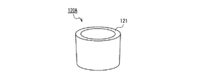
図3Aは本発明の実施の形態1に係るメス型コネクタを構成するハンドル120の概略構成を示した斜視図、図3Bはその断面図である。ハンドル120は、全体として略筒形状を有し、その上端に、フランジ部113の外径より大きな内径を有する大径部123を有し、大径部123より下側に、アダプタ110の筒状部112の外径より大きく、フランジ部113の外径より小さな内径を有する小径部122を有する。そして、小径部122と大径部123との間に、フランジ保持部121が形成されている。フランジ保持部121は、中心軸111に直交する面を有している。ハンドル120は、アダプタ120よりも高い剛性と硬度を有する材料からなり、特に制限はないが、例えば、ポリプロピレン樹脂、ポリカーボネート、ポリアセタール、PVC、PBD等を用いることができる。   FIG. 3A is a perspective view showing a schematic configuration of the handle 120 constituting the female connector according to Embodiment 1 of the present invention, and FIG. 3B is a sectional view thereof. The handle 120 has a generally cylindrical shape as a whole, and has a large diameter portion 123 having an inner diameter larger than the outer diameter of the flange portion 113 at the upper end thereof, and a cylindrical shape of the adapter 110 below the large diameter portion 123. A small-diameter portion 122 having an inner diameter larger than the outer diameter of the portion 112 and smaller than the outer diameter of the flange portion 113 is provided. A flange holding portion 121 is formed between the small diameter portion 122 and the large diameter portion 123. The flange holding part 121 has a surface orthogonal to the central axis 111. The handle 120 is made of a material having higher rigidity and hardness than the adapter 120 and is not particularly limited. For example, polypropylene resin, polycarbonate, polyacetal, PVC, PBD, or the like can be used.

図1A及び図1Bに示すように、ハンドル120の中央の貫通孔にアダプタ110が挿入されて、本実施の形態1のメス型コネクタ100が構成される。このとき、ハンドル120はアダプタ110の挿入部119の周囲を取り囲む。また、ハンドル120の大径部123内にアダプタ110のフランジ部113が収納され、且つ、フランジ部113の下面114(フランジ部113のオス型コネクタと対向する側の面とは反対側の面)がハンドル120のフランジ保持部121と当接する。これから明らかなように、フランジ部113及びフランジ保持部121は、ハンドル120がアダプタ110に対して中心軸111方向に沿って相対的に移動できる範囲の上側の終端(上限位置)を設定する移動制限手段として機能する。   As shown in FIGS. 1A and 1B, the adapter 110 is inserted into the central through hole of the handle 120 to constitute the female connector 100 of the first embodiment. At this time, the handle 120 surrounds the insertion portion 119 of the adapter 110. Further, the flange portion 113 of the adapter 110 is accommodated in the large-diameter portion 123 of the handle 120, and the lower surface 114 of the flange portion 113 (the surface on the side opposite to the surface facing the male connector of the flange portion 113). Comes into contact with the flange holding portion 121 of the handle 120. As is clear from this, the flange portion 113 and the flange holding portion 121 have a movement limit that sets the upper end (upper limit position) of the range in which the handle 120 can move relative to the adapter 110 along the direction of the central axis 111. Functions as a means.

図4は、医療用容器910及びオス型コネクタ170の一例の概略構成を示した分解図である。   FIG. 4 is an exploded view showing a schematic configuration of an example of the medical container 910 and the male connector 170.

医療用容器910は、パウチ920と、パウチ920内に液状物を注入し、又はパウチ920内に収納された液状物を取り出すためのポート930とを備えている。   The medical container 910 includes a pouch 920 and a port 930 for injecting a liquid material into the pouch 920 or taking out the liquid material stored in the pouch 920.

パウチ920は、柔軟な同一寸法の2枚のシートを重ね合わせて、その周縁のシール領域921にてヒートシール等の方法により接合してなる袋状物である。シートとしては、例えば、ポリエチレンテレフタレート、ナイロン、ポリプロピレン、ポリエチレンなどのプラスチック材料の中から互いに異なる材料を選択してなる2層以上の複合シートを用いることができる。更に、シートに、バリア層として酸化アルミニウムやシリカなどの薄膜が形成されていてもよい。パウチ920内の液状物の量などを確認することができるように、2枚のシートのうちの少なくとも一方は透明又は半透明であることが好ましい。パウチ920の、ポート930が取り付けられた位置から最も遠い位置近傍のシール領域921内に、医療用容器910を吊り下げる際に使用される開口922が形成されている。   The pouch 920 is a bag-like material formed by overlapping two flexible sheets having the same size and joining them by a method such as heat sealing in a peripheral sealing region 921. As the sheet, for example, a composite sheet having two or more layers formed by selecting different materials from plastic materials such as polyethylene terephthalate, nylon, polypropylene, and polyethylene can be used. Further, a thin film such as aluminum oxide or silica may be formed on the sheet as a barrier layer. It is preferable that at least one of the two sheets is transparent or translucent so that the amount of the liquid in the pouch 920 can be confirmed. An opening 922 used when the medical container 910 is suspended is formed in a seal region 921 in the vicinity of the position of the pouch 920 farthest from the position where the port 930 is attached.

ポート930は、液状物が通過するための貫通孔931が形成された円筒部932と、円筒部932の一端側の外周面上に設けられた接合部935と、円筒部932の他端側の外周面上に形成された雄ネジ部936とを備えている。ポート930は、更に、可撓性を有する医療用チューブを係止したり、医療用容器910を吊り下げたりする際に使用される略C字状の係止部938を備えている。ポート930は、例えば、ポリエチレン、ポリプロピレン、ポリ塩化ビニル、ポリエチレンテレフタレート、エチレン酢酸ビニルコポリマー、熱可塑性エラストマー、ポリアセタール等のパウチ920に比べて相対的に硬い材料からなり、例えば射出成型にて一体に製造することができる。接合部935は底面が略菱形である四角柱形状を有し、パウチ920を構成する2枚のシートの周縁間に挟んでヒートシールすることにより、パウチ920と接合され一体化される。   The port 930 includes a cylindrical portion 932 in which a through-hole 931 through which a liquid material passes is formed, a joint portion 935 provided on the outer peripheral surface on one end side of the cylindrical portion 932, and the other end side of the cylindrical portion 932 And an external thread portion 936 formed on the outer peripheral surface. The port 930 further includes a substantially C-shaped locking portion 938 that is used when a flexible medical tube is locked or the medical container 910 is suspended. The port 930 is made of a relatively hard material compared to the pouch 920 such as polyethylene, polypropylene, polyvinyl chloride, polyethylene terephthalate, ethylene vinyl acetate copolymer, thermoplastic elastomer, polyacetal, etc., and is manufactured integrally by injection molding, for example. can do. The joint portion 935 has a quadrangular prism shape with a substantially rhombus bottom surface, and is joined to and integrated with the pouch 920 by being heat-sealed between the peripheral edges of the two sheets constituting the pouch 920.

オス型コネクタ170は、キャップ部180と管状部172とを備えている。キャップ部180の内周面には、ポート930の雄ネジ部936と螺合する雌ネジ(図示せず)が形成されている。管状部172は、キャップ部180の下面の中央から下方に向かって突出している。本例の管状部172の外周面は、キャップ180に近づくほど外径が大きくなるテーパ面(円錐台面)を有している。管状部172には、パウチ920内の液状物が流出する貫通孔173が形成されている。オス型コネクタ170の材料は、特に制限はなく、従来から使用されている周知の材料を用いることができる。例えば、ポリプロピレン、ポリエチレン等のポリオレフィン樹脂、ポリカーボネート樹脂等を用いることができる。   The male connector 170 includes a cap part 180 and a tubular part 172. On the inner peripheral surface of the cap portion 180, a female screw (not shown) that is screwed with the male screw portion 936 of the port 930 is formed. The tubular portion 172 protrudes downward from the center of the lower surface of the cap portion 180. The outer peripheral surface of the tubular portion 172 of this example has a tapered surface (conical frustum surface) whose outer diameter increases as it approaches the cap 180. A through-hole 173 through which the liquid material in the pouch 920 flows out is formed in the tubular portion 172. The material of the male connector 170 is not particularly limited, and a conventionally known material can be used. For example, a polyolefin resin such as polypropylene or polyethylene, a polycarbonate resin, or the like can be used.

本実施の形態1のメス型コネクタ100のオス型コネクタ170への接続方法を説明する。図5Aは接続前の状態を示した断面図、図5Bは接続後の状態を示した断面図である。図5Aに示すように、ハンドル120の中央の貫通孔にアダプタ110を挿入し、ハンドル120のフランジ保持部121でアダプタ110のフランジ部113の下面114を保持する。この状態でハンドル120の外周面を2本の指で把持して、オス型コネクタ170の管状部172の外周面上にアダプタ110を被せるように矢印102の向きにアダプタ110を管状部172に外挿する。   A method for connecting the female connector 100 of the first embodiment to the male connector 170 will be described. 5A is a cross-sectional view showing a state before connection, and FIG. 5B is a cross-sectional view showing a state after connection. As shown in FIG. 5A, the adapter 110 is inserted into the central through hole of the handle 120, and the lower surface 114 of the flange portion 113 of the adapter 110 is held by the flange holding portion 121 of the handle 120. In this state, grip the outer peripheral surface of the handle 120 with two fingers, and place the adapter 110 on the tubular portion 172 in the direction of the arrow 102 so that the adapter 110 is put on the outer peripheral surface of the tubular portion 172 of the male connector 170. Insert.

アダプタ110の筒状部112の上端にフランジ部113が形成されているので、筒状部112の開口119a周縁の剛性が相対的に向上している。従って、開口119a内に管状部172を挿入する際に、管状部172の先端が開口119aの端縁に衝突しても、筒状部112は変形しにくい。よって、管状部172を開口119a内に容易に挿入することができる。   Since the flange portion 113 is formed at the upper end of the tubular portion 112 of the adapter 110, the rigidity of the periphery of the opening 119a of the tubular portion 112 is relatively improved. Therefore, when the tubular portion 172 is inserted into the opening 119a, the tubular portion 112 is not easily deformed even if the tip of the tubular portion 172 collides with the edge of the opening 119a. Therefore, the tubular portion 172 can be easily inserted into the opening 119a.

また、アダプタ110の挿入部119は、可撓性及び弾性を有するので、オス型コネクタ170の管状部172の外周面の形状に応じてその径が拡大するなどの変形をし、その弾性回復力により管状部172の外周面に密着する。   In addition, since the insertion portion 119 of the adapter 110 has flexibility and elasticity, the insertion portion 119 is deformed such that its diameter increases according to the shape of the outer peripheral surface of the tubular portion 172 of the male connector 170, and its elastic recovery force. By this, it adheres to the outer peripheral surface of the tubular portion 172.

一方、ハンドル120は高い剛性を有するので、2本の指で挟んでもほとんど変形しない。従って、2本の指がハンドル120に対してその直径方向に印加する把持力はアダプタ110の挿入部119にはほとんど伝達されない。よって、従来のゴム管902の接続作業と異なり、2本の指の把持力がアダプタ110の挿入部119と管状部172との間の摩擦力を増大させることはない。   On the other hand, since the handle 120 has high rigidity, it hardly deforms even if it is sandwiched between two fingers. Therefore, the gripping force applied by the two fingers to the handle 120 in the diameter direction is hardly transmitted to the insertion portion 119 of the adapter 110. Therefore, unlike the conventional work of connecting the rubber tube 902, the gripping force of two fingers does not increase the frictional force between the insertion portion 119 and the tubular portion 172 of the adapter 110.

また、2本の指がハンドル120に印加する矢印102の向きの力は、ハンドル120のフランジ保持部121を介してアダプタ110のフランジ部113に伝えられる。フランジ部113は、アダプタ110の矢印102の向きの前端に形成されているので、この力によってアダプタ110が座屈変形することはない。   Further, the force in the direction of the arrow 102 applied by the two fingers to the handle 120 is transmitted to the flange portion 113 of the adapter 110 via the flange holding portion 121 of the handle 120. Since the flange portion 113 is formed at the front end of the adapter 110 in the direction of the arrow 102, the adapter 110 does not buckle and deform due to this force.

以上により、本実施の形態1では、アダプタ110をオス型コネクタ170の管状部172に対して矢印102の向きに移動させるのが容易である。かくして、図5Bに示すように、管状部172の外周面にアダプタ110の挿入部119がその弾性回復力により密着した状態で、オス型コネクタ170とメス型コネクタ100とを接続することができる。オス型コネクタ170の管状部172の外周面の形状や寸法(例えばテーパ角、外径等)等がメーカや規格の違いにより異なっても、アダプタ110の挿入部119がオス型コネクタ170の管状部172の外周面に応じて弾性変形するので、オス型コネクタ170とメス型コネクタ100とを液状物の漏れなく確実に接続することができる。   As described above, in the first embodiment, it is easy to move the adapter 110 in the direction of the arrow 102 with respect to the tubular portion 172 of the male connector 170. Thus, as shown in FIG. 5B, the male connector 170 and the female connector 100 can be connected in a state where the insertion portion 119 of the adapter 110 is in close contact with the outer peripheral surface of the tubular portion 172 by its elastic recovery force. Even if the shape and dimensions (for example, taper angle, outer diameter, etc.) of the outer peripheral surface of the tubular portion 172 of the male connector 170 are different due to differences in manufacturers and standards, the insertion portion 119 of the adapter 110 is the tubular portion of the male connector 170. Since it is elastically deformed according to the outer peripheral surface of 172, the male connector 170 and the female connector 100 can be reliably connected without leakage of the liquid material.

アダプタ110の挿入部119の内周面は、図2Bに示すように、その内径が上端に近づくにしたがって大きくなるテーパ面であることが好ましい。これにより、オス型コネクタ170の管状部172の外周面の形状や寸法(例えばテーパ角、外径等)等がメーカや規格の違いにより異なっても、管状部172の外周面の少なくとも一部と挿入部119の内周面の少なくとも一部とを密着させることができるので、オス型コネクタ170とメス型コネクタ100とを液状物の漏れなく確実に接続することができる。   As shown in FIG. 2B, the inner peripheral surface of the insertion portion 119 of the adapter 110 is preferably a tapered surface whose inner diameter increases as it approaches the upper end. As a result, even if the shape and dimensions (for example, taper angle, outer diameter, etc.) of the outer peripheral surface of the tubular portion 172 of the male connector 170 are different due to differences in manufacturers and standards, at least a part of the outer peripheral surface of the tubular portion 172 Since at least a part of the inner peripheral surface of the insertion portion 119 can be brought into close contact, the male connector 170 and the female connector 100 can be reliably connected without leakage of the liquid material.

アダプタ110の挿入部119の内周面には、図2Bに示すように、周方向に沿った(即ち、中心軸111と直交する平面と挿入部119の内周面とによって形成される円に沿った)連続する環状の突起115が形成されていることが好ましい。これにより、図5Bに示すように、アダプタ110をオス型コネクタ170の管状部172に接続したとき、突起115は管状部172の外周面に密着して容易に弾性変形する。この変形の程度は、オス型コネクタ170の管状部172の形状や寸法(例えばテーパ角、外径等)等に応じて変化する。従って、オス型コネクタ170の管状部172の外周面の形状や寸法等に応じて、管状部172の外周面に挿入部119の内周面の突起115を適宜変形させ密着させることができる。環状の突起115は、図2Bに示すように中心軸111方向に複数箇所に設けることが好ましい。これにより、オス型コネクタ170の管状部172の外周面の形状や寸法等がメーカや規格の違いにより異なっても、管状部172の形状や寸法等に応じて複数の突起115のうちの少なくとも1つを選択的に管状部172の外周面に密着させて変形させることができる。但し、1つの環状の突起115のみであっても良いことは言うまでもない。   As shown in FIG. 2B, the inner peripheral surface of the insertion portion 119 of the adapter 110 is formed into a circle along the circumferential direction (that is, a circle formed by a plane orthogonal to the central axis 111 and the inner peripheral surface of the insertion portion 119). It is preferred that a continuous annular projection 115 is formed. 5B, when the adapter 110 is connected to the tubular portion 172 of the male connector 170, the protrusion 115 is in close contact with the outer peripheral surface of the tubular portion 172 and easily elastically deforms. The degree of this deformation varies depending on the shape and dimensions (for example, taper angle, outer diameter, etc.) of the tubular portion 172 of the male connector 170. Accordingly, the projection 115 on the inner peripheral surface of the insertion portion 119 can be appropriately deformed and brought into close contact with the outer peripheral surface of the tubular portion 172 according to the shape, size, etc. of the outer peripheral surface of the tubular portion 172 of the male connector 170. The annular protrusions 115 are preferably provided at a plurality of locations in the direction of the central axis 111 as shown in FIG. 2B. As a result, even if the shape, dimensions, etc. of the outer peripheral surface of the tubular portion 172 of the male connector 170 differ due to differences in manufacturers and standards, at least one of the plurality of protrusions 115 according to the shape, dimensions, etc. of the tubular portion 172. One can be selectively brought into close contact with the outer peripheral surface of the tubular portion 172 and deformed. However, it goes without saying that only one annular protrusion 115 may be provided.

アダプタ110の挿入部119の内周面には、図2Bに示すように、その内径が上端側に比べて下端側で小さくなるように階段状に変化させる段差116が、周方向に沿って連続して環状に形成されていることが好ましい。これにより、管状部172が細くても、アダプタ110を接続することができる。即ち、図6に示すように、細い管状部172の外周面は、アダプタ110の挿入部119の内周面のうち、段差116よりも下端側のより内径が小さな部分119bと密着する。従って、メス型コネクタと接続できるオス型コネクタ170の管状部172の外周面の形状や寸法等の範囲が拡大する。挿入部119の内周面のうち、段差116よりも下端側の部分は、これより上端側の部分と同様に、その内径が上端に近づくにしたがって大きくなるテーパ面であることが好ましい。また、周方向に沿った連続する環状の突起が形成されていても良い。中心軸111方向において、内径を階段状に変化させる段差116が複数箇所に設けられていても良い。   On the inner peripheral surface of the insertion portion 119 of the adapter 110, as shown in FIG. 2B, a step 116 that changes stepwise so that the inner diameter is smaller on the lower end side than on the upper end side is continuous along the circumferential direction. Thus, it is preferably formed in an annular shape. Thereby, even if the tubular part 172 is thin, the adapter 110 can be connected. That is, as shown in FIG. 6, the outer peripheral surface of the thin tubular portion 172 is in close contact with a portion 119 b having a smaller inner diameter on the lower end side than the step 116 in the inner peripheral surface of the insertion portion 119 of the adapter 110. Therefore, the range of the shape and size of the outer peripheral surface of the tubular portion 172 of the male connector 170 that can be connected to the female connector is expanded. Of the inner peripheral surface of the insertion portion 119, the lower end portion of the step 116 is preferably a tapered surface whose inner diameter increases as it approaches the upper end, like the upper end portion. Moreover, the continuous cyclic | annular protrusion along the circumferential direction may be formed. In the direction of the central axis 111, steps 116 that change the inner diameter in a step shape may be provided at a plurality of locations.

上記の実施の形態は一例であって、本発明はこれに限定されない。   The above embodiment is an example, and the present invention is not limited to this.

例えば、アダプタ110の挿入部119の内周面は、テーパ面ではなく、内径が中心軸111方向に一定の円筒面であっても良い。また、アダプタ110の挿入部119の内周面に突起115が設けられていなくても良い。また、アダプタ110の挿入部119の内周面に段差116が形成されていなくても良い。いずれの場合も、アダプタ110の挿入部119がオス型コネクタ170の管状部172の形状や寸法等に応じて弾性変形するので、オス型コネクタ170とメス型コネクタ100とを液状物の漏れなく確実に接続することができる。   For example, the inner peripheral surface of the insertion portion 119 of the adapter 110 may not be a tapered surface but may be a cylindrical surface whose inner diameter is constant in the direction of the central axis 111. Further, the protrusion 115 may not be provided on the inner peripheral surface of the insertion portion 119 of the adapter 110. Further, the step 116 may not be formed on the inner peripheral surface of the insertion portion 119 of the adapter 110. In any case, the insertion portion 119 of the adapter 110 is elastically deformed according to the shape, size, etc. of the tubular portion 172 of the male connector 170, so that the male connector 170 and the female connector 100 can be securely connected without liquid leakage. Can be connected to.

また、中心軸111方向においてフランジ部113は、図2A及び図2Bに示すようにアダプタ110の上端に設けられている必要はなく、図7A及び図7Bに示すようにアダプタ110の上端から下端側に僅かに離れた位置に設けられていても良い。アダプタ110の上端近傍にフランジ部113が形成されていれば、アダプタ110が座屈変形することなく、アダプタ110をオス型コネクタ170の管状部172に外挿することができる。アダプタ110の上端からフランジ113までの距離D1が大きすぎると、アダプタ110をオス型コネクタ170の管状部172に外挿する際に、アダプタ110の上端からフランジ113までの部分が座屈変形しやすくなる。距離D1は、アダプタ110の機械的特性等を考慮して適宜設定することができるが、一般には10.0mm以下、更には5.0mm以下が好ましい。   Further, in the direction of the central axis 111, the flange portion 113 does not have to be provided at the upper end of the adapter 110 as shown in FIGS. 2A and 2B, and the lower end side from the upper end of the adapter 110 as shown in FIGS. 7A and 7B. It may be provided at a slightly separated position. If the flange portion 113 is formed in the vicinity of the upper end of the adapter 110, the adapter 110 can be extrapolated to the tubular portion 172 of the male connector 170 without the adapter 110 being buckled. If the distance D1 from the upper end of the adapter 110 to the flange 113 is too large, the portion from the upper end of the adapter 110 to the flange 113 is likely to buckle when the adapter 110 is extrapolated to the tubular portion 172 of the male connector 170. Become. The distance D1 can be appropriately set in consideration of the mechanical characteristics of the adapter 110, etc., but is generally 10.0 mm or less, more preferably 5.0 mm or less.

また、フランジ部113は、アダプタ110の周方向に連続して環状に形成されている必要はなく、例えば図8に示す2つのフランジ部113a,113bのように周方向に互いに独立して形成されていても良い。フランジ部113を周方向に分割して形成する場合、その数は図8に示すように2つに限定されず、3つ、4つ、あるいは5つ以上であっても良い。   Further, the flange portion 113 does not need to be continuously formed in an annular shape in the circumferential direction of the adapter 110. For example, the flange portion 113 is formed independently of each other in the circumferential direction like the two flange portions 113a and 113b shown in FIG. May be. When the flange portion 113 is divided and formed in the circumferential direction, the number thereof is not limited to two as shown in FIG. 8, and may be three, four, or five or more.

上記の実施の形態に示したメス型コネクタ100では、図5Bのようにオス型コネクタ170の管状部172にメス型コネクタ100のアダプタ110を接続した後、ハンドル120から手を離すと、ハンドル120が下方に落下してしまう可能性がある。ハンドル120は、その中央の貫通孔をチューブ107が貫通しているので、チューブ107から落下してしまうことはない。しかしながら、ハンドル120がアダプタ110から遠く離れた位置に移動してしまうと、オス型コネクタ170の管状部172に対してアダプタ110の脱着作業を繰り返し行う場合などでは作業が煩雑になる。また、経腸栄養セットの製造工程において、ハンドル120がアダプタ110から離れた位置に移動すると、経腸栄養セットのハンドリング等を行う際にハンドル120に意図せずに外力が作用してハンドル120が破損してしまう可能性がある。そこで、メス型コネクタにハンドル120を所望する位置に保持する機構が設けられていることが好ましい。   In the female connector 100 shown in the above embodiment, when the adapter 110 of the female connector 100 is connected to the tubular portion 172 of the male connector 170 as shown in FIG. May fall down. Since the tube 107 penetrates the central through hole of the handle 120, the handle 120 does not fall from the tube 107. However, if the handle 120 moves to a position far away from the adapter 110, the operation becomes complicated when the adapter 110 is repeatedly attached to and detached from the tubular portion 172 of the male connector 170. In addition, when the handle 120 is moved away from the adapter 110 in the manufacturing process of the enteral nutrition set, an external force acts on the handle 120 unintentionally when handling the enteral nutrition set, and the handle 120 is moved. It may be damaged. Therefore, it is preferable that the female connector is provided with a mechanism for holding the handle 120 at a desired position.

例えば、ハンドル120を保持する機構として、図9Aに示すように、アダプタ110の筒状部112の外周面に外方向(中心軸111に直交する方向)に突出した一対の係止突起117(図9Aでは一方の係止突起117は見えない)を設けても良い。この係止突起117は、図9Bに示すように、ハンドル120の下端に当接してハンドル120が落下するのを防止する。即ち、ハンドル120は、フランジ部113と一対の係止突起117とによりアダプタ110に対する中心軸111方向の移動が制限される。係止突起117は、アダプタ110と同一材料を用いてアダプタ110と一体に成形することができる。従って、係止突起117は弾性変形可能であり、中心軸111方向において係止突起117に対して一方の側から他方の側に、係止突起117を乗り越えてハンドル120を移動させることが可能である。係止突起117の数は、図9A及び図9Bに示した例では2つであるが、本発明はこれに限定されず、1つでも良く、あるいは3以上であっても良い。複数の係止突起117を設ける場合には、中心軸111に対して等角度間隔で配置するのが好ましい。複数の係止突起117は、中心軸111方向には同一位置に設けられるのが好ましい。更には、係止突起117が、筒状部112の周方向に環状に連続していても良い。   For example, as a mechanism for holding the handle 120, as shown in FIG. 9A, a pair of locking protrusions 117 (see FIG. 9) projecting outward (direction perpendicular to the central axis 111) on the outer peripheral surface of the cylindrical portion 112 of the adapter 110. 9A, one locking projection 117 is not visible). As shown in FIG. 9B, the locking protrusion 117 contacts the lower end of the handle 120 to prevent the handle 120 from falling. That is, the handle 120 is restricted from moving in the direction of the central axis 111 with respect to the adapter 110 by the flange portion 113 and the pair of locking projections 117. The locking protrusion 117 can be formed integrally with the adapter 110 using the same material as the adapter 110. Accordingly, the locking projection 117 is elastically deformable, and the handle 120 can be moved over the locking projection 117 from one side to the other side with respect to the locking projection 117 in the direction of the central axis 111. is there. The number of the locking projections 117 is two in the example shown in FIGS. 9A and 9B, but the present invention is not limited to this, and may be one or three or more. In the case where a plurality of locking projections 117 are provided, it is preferable that they are arranged at equiangular intervals with respect to the central axis 111. The plurality of locking projections 117 are preferably provided at the same position in the direction of the central axis 111. Further, the locking protrusion 117 may be continuously annular in the circumferential direction of the cylindrical portion 112.

あるいは、ハンドル120を保持する機構として、例えば、図10A及び図10Bに示すように、アダプタ110の外周面に外方向(中心軸111に直交する方向)に突出した複数の接触突起118を設けても良い。図10Bは図10Aの10B−10B線での矢視断面図である。本例の複数の接触突起118は、アダプタ120の筒状部112の外周面に、中心軸111に対して等角度間隔で、上下方向に沿って畝状に形成されている。接触突起118は、アダプタ110と同一材料を用いてアダプタ110と一体に成形することができる。複数の接触突起118は、ハンドル120の内周面の少なくとも一部(特に小径部122の内周面)に接触して僅かに弾性変形することで発生する静摩擦力によって、ハンドル120が落下するのを防止する。接触突起118の形状や配置は図10A及び図10Bの例に限定されない。例えば、周方向に延在する畝状の突起、螺旋状に延在する畝状の突起、柱状又は錐体状の突起などいずれであっても良い。   Alternatively, as a mechanism for holding the handle 120, for example, as shown in FIGS. 10A and 10B, a plurality of contact protrusions 118 protruding outward (in a direction orthogonal to the central axis 111) are provided on the outer peripheral surface of the adapter 110. Also good. 10B is a cross-sectional view taken along line 10B-10B in FIG. 10A. The plurality of contact protrusions 118 of this example are formed in a hook shape along the vertical direction on the outer peripheral surface of the cylindrical portion 112 of the adapter 120 at equal angular intervals with respect to the central axis 111. The contact protrusion 118 can be formed integrally with the adapter 110 using the same material as the adapter 110. The plurality of contact protrusions 118 fall on the handle 120 due to a static frictional force generated by slightly contacting and elastically deforming at least a part of the inner peripheral surface of the handle 120 (particularly the inner peripheral surface of the small diameter portion 122). To prevent. The shape and arrangement of the contact protrusion 118 are not limited to the examples of FIGS. 10A and 10B. For example, any of a hook-shaped protrusion extending in the circumferential direction, a hook-shaped protrusion extending spirally, a columnar or cone-shaped protrusion, and the like may be used.

アダプタ110に図9A及び図9Bに示した係止突起117や図10A及び図10Bに示した接触突起118を設けた場合であっても、ハンドル120をアダプタ110から離れた位置に移動させることは可能である。従って、例えば、太い管状部172によって挿入部119の外径が拡大し、挿入部119の外周面がハンドル120の内周面に突き当たるために、管状部172を挿入部119に深く挿入するのが困難である場合には、挿入部119に管状部172を挿入するのに邪魔にならない位置にハンドル120を移動させることができる。   Even when the adapter 110 is provided with the locking protrusion 117 shown in FIGS. 9A and 9B and the contact protrusion 118 shown in FIGS. 10A and 10B, the handle 120 can be moved away from the adapter 110. Is possible. Therefore, for example, since the outer diameter of the insertion portion 119 is enlarged by the thick tubular portion 172 and the outer peripheral surface of the insertion portion 119 abuts against the inner peripheral surface of the handle 120, the tubular portion 172 is inserted deeply into the insertion portion 119. If it is difficult, the handle 120 can be moved to a position that does not interfere with the insertion of the tubular portion 172 into the insertion portion 119.

ハンドル120を保持する機構として、例えば、図11に示すように、アダプタ110の下端に接続されたチューブ107に保持部材150を取り付けても良い。保持部材150は、弾性変形可能な材料からなり、略ドーナツ形状を有している。保持部材150の内径はチューブ107の外径と同じかこれより僅かに小さいので、保持部材150はチューブ107の任意の位置に摩擦力を利用して固定することができる。保持部材150の外径はハンドル120の内径より大きいので、ハンドル120は保持部材150を越えてアダプタ110から遠く離れた位置に移動することはできない。保持部材150には、半径方向に沿ったスリット151が形成されている。スリット151を挟む保持部材150の2つの端面が上下方向に離間するように保持部材150を弾性変形させることにより、保持部材150を取り付けるチューブ107の長手方向における位置を変更したり、スリット151にチューブ107を通過させてチューブ107に対して保持部材150を着脱したりすることができる。図11は一例であって、本発明はこれに限定されない。例えば、保持部材が、平行に配置した2本の棒状部材でチューブ107を挟持するように構成されていても良い。また、保持部材はチューブに対して接着又は溶着などの方法により固着されていても良い。更に、上述と同様の構成を有する保持部材をチューブ107ではなく、アダプタ110の下端近傍に取り付けても良い。   As a mechanism for holding the handle 120, for example, as shown in FIG. 11, a holding member 150 may be attached to a tube 107 connected to the lower end of the adapter 110. The holding member 150 is made of an elastically deformable material and has a substantially donut shape. Since the inner diameter of the holding member 150 is the same as or slightly smaller than the outer diameter of the tube 107, the holding member 150 can be fixed to an arbitrary position of the tube 107 using a frictional force. Since the outer diameter of the holding member 150 is larger than the inner diameter of the handle 120, the handle 120 cannot move beyond the holding member 150 to a position far away from the adapter 110. A slit 151 is formed in the holding member 150 along the radial direction. The holding member 150 is elastically deformed so that the two end faces of the holding member 150 sandwiching the slit 151 are separated in the vertical direction, thereby changing the position in the longitudinal direction of the tube 107 to which the holding member 150 is attached, The holding member 150 can be attached to and detached from the tube 107 through the passage 107. FIG. 11 is an example, and the present invention is not limited to this. For example, the holding member may be configured to sandwich the tube 107 with two rod-shaped members arranged in parallel. The holding member may be fixed to the tube by a method such as adhesion or welding. Further, a holding member having the same configuration as described above may be attached in the vicinity of the lower end of the adapter 110 instead of the tube 107.

あるいは、ハンドル120を保持する機構として、例えば、図12に示すように、ハンドル120自身に保持部材160を取り付けても良い。保持部材160は、チューブ107に装着されるバンド161と、バンド161とハンドル120とを繋ぐヒモ162とからなる。バンド161は可撓性を有し、その一端には突起163が形成され、他端には貫通孔164が形成されている。突起163と貫通孔164との間の距離はチューブ107の外周長とほぼ同じかこれより短い。バンド161をチューブ107の外周面に巻き付けて、突起163を貫通孔164に挿入して両者を係合させることで、バンド161はチューブ107の外周面を締め付けるようにして装着される。この状態では、ハンドル120は、ヒモ162の長さを超えてバンド161から遠く離れた位置に移動することはできない。バンド161の長さを適切に調整して、バンド161をチューブ107ではなく、アダプタ110の下端近傍に装着しても良い。   Alternatively, as a mechanism for holding the handle 120, for example, as shown in FIG. 12, a holding member 160 may be attached to the handle 120 itself. The holding member 160 includes a band 161 attached to the tube 107 and a string 162 connecting the band 161 and the handle 120. The band 161 has flexibility, a protrusion 163 is formed at one end, and a through hole 164 is formed at the other end. The distance between the protrusion 163 and the through hole 164 is substantially the same as or shorter than the outer peripheral length of the tube 107. The band 161 is mounted so that the outer peripheral surface of the tube 107 is tightened by winding the band 161 around the outer peripheral surface of the tube 107 and inserting the protrusions 163 into the through holes 164 to engage them. In this state, the handle 120 cannot move to a position far from the band 161 beyond the length of the strap 162. The length of the band 161 may be appropriately adjusted so that the band 161 is attached not near the tube 107 but near the lower end of the adapter 110.

図3A及び図3Bに示したハンドル120は、アダプタ110のフランジ部113を収納するために大径部123を備えていたが、本発明のハンドルは、フランジ部113の下面114を保持するフランジ保持部121を有していれば良く、大径部123を備えていなくても良い。例えば、図13A及び図13Bに示すハンドル120Aのように、内周面及び外周面が階段状の段差のないテーパ面であっても良い。この場合、ハンドル120Aの上側端面がフランジ保持部121として機能する。   The handle 120 shown in FIGS. 3A and 3B includes the large-diameter portion 123 for accommodating the flange portion 113 of the adapter 110. However, the handle according to the present invention holds the flange 114 that holds the lower surface 114 of the flange portion 113. It is only necessary to have the portion 121, and the large diameter portion 123 may not be provided. For example, like the handle 120A shown in FIGS. 13A and 13B, the inner peripheral surface and the outer peripheral surface may be tapered surfaces having no stepped steps. In this case, the upper end surface of the handle 120 </ b> A functions as the flange holding portion 121.

更に、ハンドルの上方及び下方から見た形状は円形に限定されない。例えば、上方及び下方から見た形状が、図14Aに示すハンドル120Bのような四角形や、図14Bに示すハンドル120Cのような三角形であっても良く、またはこれら以外の多角形、楕円形、長円形などであっても良い。更に、上方及び下方から見たとき、ハンドルの外周面の形状と内周面の形状とが一致している必要はない。例えば、上方及び下方から見たとき、アダプタを取り囲む内周面は円形であり、外周面は四角形であっても良い。また、ハンドルの内周面に、周方向に沿って複数のドーム状、円筒面状等の突起や歯車状の凹凸が形成されていても良く、また、微細な凹凸模様が形成されていても良い。   Furthermore, the shape seen from above and below the handle is not limited to a circle. For example, the shape seen from above and below may be a quadrangle like the handle 120B shown in FIG. 14A or a triangle like the handle 120C shown in FIG. 14B, or other polygons, ellipses, and long shapes. It may be circular. Furthermore, when viewed from above and below, the shape of the outer peripheral surface of the handle and the shape of the inner peripheral surface do not have to match. For example, when viewed from above and below, the inner peripheral surface surrounding the adapter may be circular, and the outer peripheral surface may be rectangular. Further, a plurality of dome-shaped, cylindrical surface-like projections and gear-shaped irregularities may be formed on the inner peripheral surface of the handle along the circumferential direction, and a fine irregular pattern may be formed. good.

また、ハンドルの内周面の内寸法及び/又は外周面の外寸法は、上端側が下端側よりも大きくなるようにテーパ状に変化している必要はなく、中心軸111方向において一定であっても良い。あるいは、上端側が下端側よりも小さくなるようにテーパ状に変化していても良い。   Further, the inner dimension of the inner peripheral surface of the handle and / or the outer dimension of the outer peripheral surface need not change in a tapered shape so that the upper end side is larger than the lower end side, and is constant in the direction of the central axis 111. Also good. Or you may change in the taper shape so that an upper end side may become smaller than a lower end side.

特に、図15A及び図15B示すハンドル120Dのように、その内周面の内寸法が、上端側が下端側よりも小さくなるようにテーパ状に変化していても良い。図5Aに示したように、一般にオス型コネクタの管状部172の外周面は、その先端ほど外径が小さくなるテーパ面であることが多い。このようなオス型コネクタの管状部172に対して図15A及び図15B示すハンドル120Dを用いると、内径が最小となる、上端面の開口端縁131が、管状部172が挿入された挿入部119に局所的に密着し締め付ける。即ち、挿入部119の局所が、その内側の管状部172とその外側のハンドル120Dの開口端縁131とで強く挟まれるという「かしめ効果」が得られる。これにより、オス型コネクタの管状部172とアダプタ110との接続強度が向上する。従って、かしめ効果を利用した場合には、利用しない場合に比べて、管状部172からのアダプタ110の意図しない脱落が減少し、安全性が向上する。   In particular, as in the handle 120D shown in FIGS. 15A and 15B, the inner dimension of the inner peripheral surface may change in a tapered shape so that the upper end side is smaller than the lower end side. As shown in FIG. 5A, in general, the outer peripheral surface of the tubular portion 172 of the male connector is often a tapered surface having a smaller outer diameter at the tip. When the handle 120D shown in FIGS. 15A and 15B is used for the tubular portion 172 of such a male connector, the opening edge 131 of the upper end surface having the minimum inner diameter is the insertion portion 119 in which the tubular portion 172 is inserted. Tighten it locally. That is, a “caulking effect” is obtained in which the local portion of the insertion portion 119 is strongly sandwiched between the inner tubular portion 172 and the opening edge 131 of the outer handle 120D. Thereby, the connection strength between the tubular portion 172 of the male connector and the adapter 110 is improved. Therefore, when the caulking effect is used, unintentional drop-off of the adapter 110 from the tubular portion 172 is reduced compared to the case where it is not used, and safety is improved.

上述のかしめ効果を発揮するハンドルの形状は、図15A及び図15B示すハンドル120Dに限定されない。例えば、図16A及び図16Bに示すハンドル120Eのように、その内周面上の、フランジ保持部121より僅かに離れた位置に、内寸法が他の部分よりも小さな径小部132を形成しても良い。径小部132は、周方向に連続して環状に形成されている。径小部132の上側の端縁133が、管状部172が挿入された挿入部119に局所的に密着し締め付けて、かしめ効果を発揮する。径小部132の内周面の内寸法は、図16A及び図16Bでは、上側が下側よりも小さくなるようにテーパ状に変化している。これにより、より大きなかしめ効果が得られる。但し、径小部132の内周面の内寸法は、上下方向において一定であっても良い。   The shape of the handle that exhibits the caulking effect described above is not limited to the handle 120D shown in FIGS. 15A and 15B. For example, like the handle 120E shown in FIGS. 16A and 16B, a small-diameter portion 132 whose inner dimension is smaller than other portions is formed on the inner peripheral surface at a position slightly away from the flange holding portion 121. May be. The small diameter portion 132 is formed in an annular shape continuously in the circumferential direction. The upper edge 133 of the small-diameter portion 132 is brought into close contact with and tightly attached to the insertion portion 119 in which the tubular portion 172 is inserted, thereby exerting a caulking effect. In FIG. 16A and FIG. 16B, the inner dimension of the inner peripheral surface of the small-diameter portion 132 changes in a tapered shape so that the upper side is smaller than the lower side. Thereby, a larger caulking effect can be obtained. However, the inner dimension of the inner peripheral surface of the small diameter portion 132 may be constant in the vertical direction.

図15A及び図15B、図16A及び図16Bでは、ハンドルが、管状部172が挿入された挿入部119の外周面に密着する位置が、周方向に連続する環状となるが、本発明はこれに限らず、ハンドルが挿入部119の外周面に密着する位置が周方向に不連続であっても良い。例えば、ハンドルの内周面の、挿入部119の外周面に密着する位置に、周方向に沿って複数のドーム状、円筒面状等の突起や歯車状の凹凸を形成したり、挿入部119の外周面に密着するハンドルの内周面を、多角形や楕円形にしたりすることで、挿入部119がかしめられる位置を不連続にしても良い。   In FIGS. 15A and 15B, and FIGS. 16A and 16B, the position where the handle is in close contact with the outer peripheral surface of the insertion portion 119 into which the tubular portion 172 is inserted is an annular shape that is continuous in the circumferential direction. Not limited to this, the position at which the handle is in close contact with the outer peripheral surface of the insertion portion 119 may be discontinuous in the circumferential direction. For example, a plurality of dome-shaped, cylindrical surface-like projections or gear-shaped irregularities are formed along the circumferential direction at positions where the inner peripheral surface of the handle is in close contact with the outer peripheral surface of the insertion portion 119, or the insertion portion 119 is formed. The position where the insertion portion 119 is caulked may be made discontinuous by making the inner peripheral surface of the handle in close contact with the outer peripheral surface of the handle into a polygon or an ellipse.

また、ハンドルの外周面に、指に対する把持性や滑り防止特性を向上させるために、各種の凹凸形状等を設けても良い。   In addition, various uneven shapes may be provided on the outer peripheral surface of the handle in order to improve the gripping property against a finger and the anti-slip property.

また、上記のハンドル120,120A,120B,120C,120D,120Eはいずれもアダプタ110を切れ目なく取り囲む環状形状を有していたが、本発明のハンドルはこれに限定されない。例えば、図17に示すハンドル120Fのように、周方向に不連続となるように、ハンドル120Fの上端と下端とを結ぶスリット125が形成されていても良い。このハンドル120Fの上方及び下方から見た形状は略C字状である。これにより、例えば以下の効果が得られる。太い管状部172にハンドルを用いてアダプタ110を装着する場合、管状部172の外径に応じてアダプタ110の挿入部119は伸びてその外径は大きくなる。ハンドルにスリット125が形成されていない場合、挿入部119の外径の上限はアダプタの外周面と当接するハンドルの内周面の内径に一致する。従って、アダプタ110を接続できる管状部172の外径の上限は、ハンドルのこの内径に依存する。これに対して、スリット125が形成されたハンドル120Fであれば、ハンドル120Fが弾性変形することによりその内周面の内径を拡大させることができる。従って、同一の内径を有するハンドルであっても、スリット125が形成されていないハンドルに比べて、スリット125が形成されているハンドル120Fを使用すれば、より太い管状部172にアダプタ110を接続することができる。   Further, although the handles 120, 120A, 120B, 120C, 120D, and 120E all have an annular shape that surrounds the adapter 110 without any break, the handle of the present invention is not limited to this. For example, like the handle 120F shown in FIG. 17, a slit 125 that connects the upper end and the lower end of the handle 120F may be formed so as to be discontinuous in the circumferential direction. The shape of the handle 120F viewed from above and below is substantially C-shaped. Thereby, for example, the following effects can be obtained. When the adapter 110 is attached to the thick tubular portion 172 using a handle, the insertion portion 119 of the adapter 110 extends and the outer diameter increases according to the outer diameter of the tubular portion 172. When the slit 125 is not formed in the handle, the upper limit of the outer diameter of the insertion portion 119 coincides with the inner diameter of the inner peripheral surface of the handle that contacts the outer peripheral surface of the adapter. Therefore, the upper limit of the outer diameter of the tubular portion 172 to which the adapter 110 can be connected depends on the inner diameter of the handle. On the other hand, if the handle 120F is formed with the slit 125, the inner diameter of the inner peripheral surface can be increased by elastically deforming the handle 120F. Therefore, even if the handles have the same inner diameter, the adapter 110 is connected to the thicker tubular portion 172 if the handle 120F having the slit 125 is used compared to the handle having no slit 125 formed. be able to.

スリット125の周方向の幅D2は特に制限はない。アダプタ110及びこれに接続されたチューブ107が通過できないように幅D2を狭く設定すれば、ハンドル120Fの脱落を防止できる。逆に、例えばチューブ107が通過できる程度に幅D2を広く設定することもできる。これにより、ハンドル120Fを用いてオス型コネクタ170の管状部172にアダプタ110を接続した後にハンドル120Fを取り外したり、その後、再度ハンドル120Fを取り付けたりすることができる。即ち、ハンドル120Fを脱着可能なメス型コネクタを実現できる。例えば、オス型コネクタの太い管状部172によってアダプタ110の挿入部119の外径が拡大して、ハンドル120Fの弾性変形がその許容範囲の上限を越える場合には、ハンドル120Fをアダプタ110から取り外しても良い。また、ハンドルがオス型コネクタに適合する係合形状(後述する実施の形態2〜4を参照)を有していない場合には、アダプタ110と管状部172とを接続した後、ハンドルを取り外しても良い。また、その後、アダプタを別の管状部に接続する場合には、ハンドルを再装着することができる。   The circumferential width D2 of the slit 125 is not particularly limited. If the width D2 is set to be narrow so that the adapter 110 and the tube 107 connected to the adapter 110 cannot pass, it is possible to prevent the handle 120F from falling off. Conversely, for example, the width D2 can be set wide enough to allow the tube 107 to pass therethrough. Accordingly, the handle 120F can be removed after the adapter 110 is connected to the tubular portion 172 of the male connector 170 using the handle 120F, and then the handle 120F can be attached again. That is, a female connector to which the handle 120F can be attached and detached can be realized. For example, when the outer diameter of the insertion portion 119 of the adapter 110 is enlarged by the thick tubular portion 172 of the male connector and the elastic deformation of the handle 120F exceeds the upper limit of the allowable range, the handle 120F is removed from the adapter 110. Also good. In addition, when the handle does not have an engagement shape (see Embodiments 2 to 4 described later) that fits the male connector, after the adapter 110 and the tubular portion 172 are connected, the handle is removed. Also good. Further, when the adapter is connected to another tubular portion thereafter, the handle can be remounted.

図18A及び図18Bに示すハンドル120Gには、ハンドル120Gの上端と下端とを結ぶスリット126が形成されている。スリット126に対向する位置には、肉厚を相対的に薄くすることで弾性変形が可能なヒンジ127が形成されている。即ち、ハンドル120Gは2つの半体120G1,120G2を有し、半体120G1,120G2のそれぞれの一端間にはスリット126が形成されており、それぞれの他端はヒンジ127を介して接続されている。スリット126を介して対向する2つの半体120G1,120G2の端面には、互いに嵌合する嵌合形状128a,128bが形成されている。ヒンジ127を弾性変形させることで、ヒンジ127を中心として2つの半体120G1,120G2を矢印129a,129b方向に回動させることができ、これにより、スリット126を介して対向する2つの半体120G1,120G2の端面を接離することができる。嵌合形状128a,128bは、2つの半体120G1,120G2の端面を接触させたときに、両端面間の位置ずれを防止する。このハンドル120Gは、ハンドル120Fと同様に、太い管状部172にアダプタ110を接続することを可能にする。また、ハンドル120Gを脱着可能なメス型コネクタを実現できる。 The handle 120G shown in FIGS. 18A and 18B is formed with a slit 126 connecting the upper end and the lower end of the handle 120G. A hinge 127 that can be elastically deformed by making the thickness relatively thin is formed at a position facing the slit 126. That is, the handle 120G has two halves 120G 1 , 120G 2 , slits 126 are formed between the respective one ends of the halves 120G 1 , 120G 2 , and the other ends are connected via hinges 127. It is connected. Fitting shapes 128a and 128b that fit each other are formed on the end faces of the two halves 120G 1 and 120G 2 that face each other through the slit 126. By elastically deforming the hinge 127, the two halves 120G 1 and 120G 2 can be rotated in the directions of the arrows 129a and 129b around the hinge 127, whereby two halves facing each other through the slit 126 can be rotated. The end surfaces of the bodies 120G 1 and 120G 2 can be contacted and separated. The fitting shapes 128a and 128b prevent displacement between both end faces when the end faces of the two halves 120G 1 and 120G 2 are brought into contact with each other. The handle 120G enables the adapter 110 to be connected to the thick tubular portion 172, similar to the handle 120F. Moreover, the female connector which can attach or detach the handle 120G is realizable.

図17、図18A及び図18Bに示したようにハンドル120F,120Gにスリット125,126を形成すると、ハンドル120F,120Gの剛性が低下するので、上述したハンドルによるかしめ効果は低下する。スリットが形成されていても、所望するかしめ効果を得るために、図19A及び図19Bに示すようにハンドルの拡径を制限する拡径制限手段140を設けて良い。図19A及び図19Bに示したハンドル120G’は、拡径制限手段140が設けられている点を除いて図18A及び図18Bに示したハンドル120Gと同じである。図19Aに示すように、拡径制限手段140は、伸びにくい(即ち、極めて高いバネ係数を有する)材料からなり且つ可撓性を有するバンド141を含む。バンド141の一端は半体120G1に固定ピン142を用いて固定され、他端には係止ピン143が取り付けられている。半体120G2には係止孔144が形成されている。ハンドル120G’によるかしめ効果を必要とする場合には、図19Bに示すように、係止ピン143を係止孔144に挿入する。管状部172の外径が太い場合、2つの半体120G1,120G2が互いに離れるようにヒンジ127が弾性変形してハンドル120G’が拡径するが、2つの半体120G1,120G2間に架け渡されたバンド141がその拡径を制限する。これにより、かしめ効果を得ることができる。管状部172の外径に応じてハンドル120G’が拡径できる上限を変更することが好ましく、そのためには、例えばバンド141の長さを変更したり、異なる位置に複数の係止孔144を形成しておき、係止ピン143を挿入する係止孔144を適宜変更したりすればよい。図19A及び図19Bでは、図18A及び図18Bに示したハンドル120Gに拡径制限手段140を設けた例を示したが、図17に示したハンドル120Fに同様の拡径制限手段を設けても良い。図19A及び図19Bに示した拡径制限手段140は一例であり、ハンドルの拡径を制限することができればこの構成に限定されない。 When slits 125 and 126 are formed in handles 120F and 120G as shown in FIGS. 17, 18A, and 18B, the rigidity of handles 120F and 120G decreases, so that the caulking effect by the handle described above decreases. Even when the slit is formed, in order to obtain a desired caulking effect, an expansion limiting means 140 for limiting the expansion of the handle may be provided as shown in FIGS. 19A and 19B. The handle 120G ′ shown in FIGS. 19A and 19B is the same as the handle 120G shown in FIGS. 18A and 18B, except that the diameter expansion limiting means 140 is provided. As shown in FIG. 19A, the diameter expansion limiting means 140 includes a band 141 made of a material that is difficult to stretch (that is, having a very high spring coefficient) and having flexibility. One end of the band 141 is fixed by using a fixing pin 142 to the half 120G 1, the locking pin 143 is attached to the other end. The halves 120G 2 locking hole 144 is formed. When the caulking effect by the handle 120G ′ is required, the locking pin 143 is inserted into the locking hole 144 as shown in FIG. 19B. If the outer diameter of the tubular portion 172 is thick, the two halves 120G 1, 120G 2 Although hinge 127 away from each other to the enlarged diameter handle 120G 'is elastically deformed, the two halves 120G 1, 120G 2 between The band 141 spanned between the two restricts the diameter expansion. Thereby, the caulking effect can be obtained. It is preferable to change the upper limit of the diameter of the handle 120G ′ according to the outer diameter of the tubular portion 172. For this purpose, for example, the length of the band 141 is changed, or a plurality of locking holes 144 are formed at different positions. In addition, the locking hole 144 for inserting the locking pin 143 may be changed as appropriate. 19A and 19B show an example in which the diameter expansion restriction means 140 is provided on the handle 120G shown in FIGS. 18A and 18B, but a similar diameter expansion restriction means may be provided on the handle 120F shown in FIG. good. The diameter expansion limiting means 140 shown in FIGS. 19A and 19B is an example, and is not limited to this configuration as long as the diameter expansion of the handle can be limited.

本発明のメス型コネクタの移動制限手段は、ハンドルがアダプタに対してアダプタの中心軸111方向に沿って相対的に移動できる範囲の上側の終端(上限位置)を少なくとも設定する。その一例として、上述したメス型コネクタ100は、アダプタ110にフランジ部113が設けられ、ハンドル120にフランジ部113の下面と当接するフランジ保持部121が設けられていた(図1)。   The movement restriction means for the female connector according to the present invention sets at least the upper end (upper limit position) of the range in which the handle can move relative to the adapter along the direction of the central axis 111 of the adapter. As an example, in the female connector 100 described above, the adapter 110 is provided with the flange portion 113, and the handle 120 is provided with the flange holding portion 121 that contacts the lower surface of the flange portion 113 (FIG. 1).

しかしながら、本発明のメス型コネクタの移動制限手段は、これに限定されず、更に、ハンドルがアダプタに対してアダプタの中心軸111方向に沿って相対的に移動できる範囲の下側の終端(下限位置)も設定しても良い。   However, the movement limiting means for the female connector of the present invention is not limited to this, and further, the lower end (lower limit) of the range in which the handle can move relative to the adapter along the direction of the central axis 111 of the adapter. Position) may also be set.

図20Aはアダプタに対するハンドルの移動範囲の上側及び下側の終端を設定する移動制限手段を備えた実施の形態1に係るメス型コネクタ100Aの概略構成を示した斜視図、図20Bはその断面図である。図21Aはメス型コネクタ100Aを構成するアダプタ110Aの概略構成を示した斜視図、図21Bはその断面図である。図22Aはメス型コネクタ100Aを構成するハンドル120Hの概略構成を示した斜視図、図22Bはその断面図である。これらの図において、図1A、図1B、図2A、図2B、図3A、図3B中の部材と同一の機能を有する部材には同一の符号を付して、それらの説明を省略する。   20A is a perspective view showing a schematic configuration of the female connector 100A according to the first embodiment provided with movement restriction means for setting upper and lower ends of the movement range of the handle with respect to the adapter, and FIG. 20B is a cross-sectional view thereof. It is. FIG. 21A is a perspective view showing a schematic configuration of an adapter 110A constituting the female connector 100A, and FIG. 21B is a sectional view thereof. 22A is a perspective view showing a schematic configuration of a handle 120H constituting the female connector 100A, and FIG. 22B is a sectional view thereof. In these drawings, members having the same functions as those in FIGS. 1A, 1B, 2A, 2B, 3A, and 3B are denoted by the same reference numerals, and description thereof is omitted.

図21A及び図21Bに示すアダプタ110Aは、フランジ部113を備えていない点、及び、筒状部112の外周面に周方向に沿った環状の溝190が形成されている点で、図2A及び図2Bに示されたアダプタ110と異なる。   The adapter 110A shown in FIGS. 21A and 21B does not include the flange portion 113, and the annular groove 190 along the circumferential direction is formed on the outer peripheral surface of the cylindrical portion 112. Different from the adapter 110 shown in FIG. 2B.

図22A及び図22Bに示すハンドル120Hは、フランジ保持部121及び大径部123を備えていない点、及び、内周面に突出した、周方向に沿った環状の嵌入部191が形成されている点で、図3A及び図3Bに示されたハンドル120と異なる。   The handle 120H shown in FIGS. 22A and 22B is provided with a flange holding portion 121 and a large-diameter portion 123, and an annular fitting portion 191 extending in the circumferential direction protruding from the inner peripheral surface. This is different from the handle 120 shown in FIGS. 3A and 3B.

図20A及び図20Bに示すように、アダプタ110Aの溝190にハンドル120Hの嵌入部191が嵌入する。これから明らかなように、このメス型コネクタ100Aでは、アダプタ110Aの溝190及びハンドル120Hの嵌入部191は、ハンドル120Hがアダプタ110Aに対して中心軸111方向に沿って相対的に移動できる範囲の上側及び下側の終端(上限位置及び下限位置)を設定する移動制限手段として機能する。   As shown in FIGS. 20A and 20B, the fitting portion 191 of the handle 120H is fitted into the groove 190 of the adapter 110A. As is clear from this, in this female connector 100A, the groove 190 of the adapter 110A and the fitting portion 191 of the handle 120H are located above the range in which the handle 120H can move relative to the adapter 110A along the direction of the central axis 111. And it functions as a movement limiting means for setting the lower end (upper limit position and lower limit position).

また、ハンドル120Hに設けられた嵌入部191に、上記のかしめ効果を発揮させることができる。   Further, the above-described caulking effect can be exerted on the fitting portion 191 provided on the handle 120H.

溝190の中心軸111方向の幅をW1、嵌入部191の中心軸方向の幅をW2としたとき、1.0≦W1/W2≦1.5を満足することが好ましい。W1/W2がこの下限より小さいと、アダプタ110Aの溝190内にハンドル120Hの嵌入部191を嵌入させることが困難である。W1/W2がこの上限より大きいと、アダプタ110Aに対するハンドル120Hの相対的な可動範囲が大きくなるので、アダプタ110Aの中心軸111に対してハンドル120Hの中心軸が傾きやすくなり、傾いたハンドル120Hの向きを修正するなどの煩雑な作業を強いられたり、溝190から嵌入部191が外れたりすることがある。   When the width of the groove 190 in the direction of the central axis 111 is W1, and the width of the fitting portion 191 in the direction of the central axis is W2, it is preferable that 1.0 ≦ W1 / W2 ≦ 1.5 is satisfied. If W1 / W2 is smaller than this lower limit, it is difficult to fit the fitting portion 191 of the handle 120H into the groove 190 of the adapter 110A. If W1 / W2 is larger than this upper limit, the relative movable range of the handle 120H with respect to the adapter 110A becomes large, so that the center axis of the handle 120H tends to tilt with respect to the center axis 111 of the adapter 110A, and the tilted handle 120H A complicated operation such as correcting the orientation may be forced, or the fitting portion 191 may be detached from the groove 190.

上記のメス型コネクタ100Aでは、ハンドル120Hの内周面の中心軸111方向の一部を突出させて嵌入部191を形成したが、ハンドル120Hの内周面の中心軸111方向の全部を嵌入部としても良い。即ち、アダプタ110Aに形成された溝190内に、ハンドルの中心軸111方向の全部が嵌入するように構成しても良い。   In the female connector 100A, the fitting portion 191 is formed by projecting part of the inner peripheral surface of the handle 120H in the direction of the central axis 111. However, the whole fitting portion of the inner peripheral surface of the handle 120H in the direction of the central axis 111 is formed. It is also good. In other words, the handle 190 may be configured so that the entire handle 110 is fitted in the groove 190 formed in the adapter 110A.

上記のメス型コネクタ100Aでは、アダプタ110Aのハンドル120Hに対向する面に溝190を設け、ハンドル120Hのアダプタ110Aに対向する面に嵌入部191を設けたが、ハンドル120Hのアダプタ110Aに対向する面に溝を設け、アダプタ110Aのハンドル120Hに対向する面にこの溝に嵌入する嵌入部を設けても良い。   In the female connector 100A, the groove 190 is provided on the surface of the adapter 110A that faces the handle 120H, and the fitting portion 191 is provided on the surface of the handle 120H that faces the adapter 110A, but the surface of the handle 120H that faces the adapter 110A. A groove may be provided in the adapter 110A, and a fitting portion that fits into the groove may be provided on the surface of the adapter 110A facing the handle 120H.

図23Aはアダプタに対するハンドルの移動範囲の上側及び下側の終端を設定する移動制限手段を備えた実施の形態1に係るメス型コネクタ100Bの概略構成を示した斜視図、図23Bはその断面図である。メス型コネクタ100Bは、アダプタ110Bと、アダプタ110Bに外装されるハンドル120Iとを備える。図23A及び図23Bにおいて、図1A、図1B中の部材と同一の機能を有する部材には同一の符号を付して、それらの説明を省略する。   FIG. 23A is a perspective view showing a schematic configuration of the female connector 100B according to Embodiment 1 provided with movement restriction means for setting upper and lower ends of the movement range of the handle relative to the adapter, and FIG. 23B is a cross-sectional view thereof. It is. The female connector 100B includes an adapter 110B and a handle 120I that is externally mounted on the adapter 110B. 23A and 23B, members having the same functions as those in FIGS. 1A and 1B are denoted by the same reference numerals, and description thereof is omitted.

図23A及び図23Bに示すメス型コネクタ100Bは、アダプタ110Bがフランジ部113を備えていない点、ハンドル120Iがフランジ保持部121及び大径部123を備えていない点、及び、アダプタ110Bとハンドル120Iとが固着部195で固着されている点で、図1A及び図1Bに示されたメス型コネクタ100と異なる。このメス型コネクタ100Bでは、固着部195が、ハンドル120Iがアダプタ110Bに対して中心軸111方向に沿って相対的に移動できる範囲の上側及び下側の終端(上限位置及び下限位置)を設定する移動制限手段として機能する。   The female connector 100B shown in FIG. 23A and FIG. 23B is that the adapter 110B does not include the flange portion 113, the handle 120I does not include the flange holding portion 121 and the large diameter portion 123, and the adapter 110B and the handle 120I. Are different from the female connector 100 shown in FIGS. 1A and 1B in that they are fixed by a fixing portion 195. In this female connector 100B, the fixing portion 195 sets upper and lower end points (upper limit position and lower limit position) of the range in which the handle 120I can move relative to the adapter 110B along the direction of the central axis 111. Functions as movement restriction means.

固着部195でのアダプタ110Bとハンドル120Iとの固着方法は、特に制限はないが、例えば、接着剤の塗布、溶着などを用いることができる。   The method for fixing the adapter 110B and the handle 120I at the fixing portion 195 is not particularly limited, and for example, application of adhesive, welding, or the like can be used.

上記のメス型コネクタ100A,100Bに対して、上述した各種の変更例を適用することができる。但し、アダプタ110A,100Bに対するハンドル120H,120Iの移動範囲が制限されているので、このような移動制限手段を備えるメス型コネクタには図9〜図12に示したハンドルを所定位置に保持する機構は不要である。   The various modifications described above can be applied to the female connectors 100A and 100B. However, since the movement range of the handles 120H and 120I with respect to the adapters 110A and 100B is limited, the female connector having such a movement restriction means has a mechanism for holding the handle shown in FIGS. 9 to 12 in a predetermined position. Is unnecessary.

(実施の形態2)
本実施の形態2では、オス型コネクタの管状部に接続されたアダプタが管状部から意図せずに脱落するのを防止するための係合形状がハンドルに設けられたメス型コネクタ、及びこれに対応した係合形状が設けられたオス型コネクタを説明する。
(Embodiment 2)
In the second embodiment, an engagement shape for preventing an adapter connected to the tubular portion of the male connector from being unintentionally dropped from the tubular portion is provided in the handle, and to this A male connector provided with a corresponding engagement shape will be described.

図24は本発明の実施の形態2に係るオス型コネクタ270の斜視図である。図25Aはオス型コネクタ270の正面図、図25Bはその下面図である。図24において、一点鎖線271はオス型コネクタ270の中心軸である。中心軸271の方向を上下方向とし、図24の紙面上側(医療用容器910のポート930に接続される側)を「上側」、紙面下側(メス型コネクタが接続される側)を「下側」と呼ぶことにする。   FIG. 24 is a perspective view of male connector 270 according to Embodiment 2 of the present invention. 25A is a front view of the male connector 270, and FIG. 25B is a bottom view thereof. In FIG. 24, an alternate long and short dash line 271 is the central axis of the male connector 270. The direction of the central axis 271 is the vertical direction, the upper side of the paper (the side connected to the port 930 of the medical container 910) in FIG. 24 is “upper”, and the lower side of the paper (the side to which the female connector is connected) is “lower”. We will call it “side”.

キャップ部280の内周面には、医療用容器910のポート930の雄ネジ部936(図4参照)と螺合する雌ネジ281が形成されている(図30参照)。キャップ部280の下面には、その中央の円形の領域がその周囲の環状領域283よりも下方に高さHM21だけ突出した台座282が形成されている。台座282の中央に、下方に向かって突出した管状部272が設けられている。本例の管状部272の外周面は、キャップ280に近づくほど外径が大きくなるテーパ面(円錐台面)を有している。管状部272には、パウチ920内の液状物が流出する貫通孔273が形成されている。   On the inner peripheral surface of the cap portion 280, a female screw 281 that is screwed with the male screw portion 936 (see FIG. 4) of the port 930 of the medical container 910 is formed (see FIG. 30). On the lower surface of the cap portion 280, a base 282 is formed in which a central circular region protrudes by a height HM21 below a surrounding annular region 283. A tubular portion 272 protruding downward is provided at the center of the pedestal 282. The outer peripheral surface of the tubular portion 272 of this example has a tapered surface (conical frustum surface) whose outer diameter increases as it approaches the cap 280. A through-hole 273 through which the liquid material in the pouch 920 flows out is formed in the tubular portion 272.

台座282の外周面には、中心軸271に対して対称位置に、一対の係合爪284が中心軸271に対して放射方向に突出して形成されている。係合爪284は、ほぼ水平方向に沿って延びた係合片285と、係合片285の一端に上方向に突出して形成されたロック突起286とを備える。台座282の下面は平面であり、この下面と一対の係合爪284の下面とは一致している。一対の係合爪284の形状は中心軸271に対して対称である。台座282の外径はDM21、一対の係合爪284の頂部間距離はDM22(DM22>DM21)である。   On the outer peripheral surface of the pedestal 282, a pair of engaging claws 284 are formed in a symmetric position with respect to the central axis 271 so as to protrude in the radial direction with respect to the central axis 271. The engagement claw 284 includes an engagement piece 285 extending substantially in the horizontal direction, and a lock protrusion 286 formed at one end of the engagement piece 285 so as to protrude upward. The lower surface of the pedestal 282 is a flat surface, and this lower surface coincides with the lower surfaces of the pair of engaging claws 284. The shape of the pair of engaging claws 284 is symmetric with respect to the central axis 271. The outer diameter of the base 282 is DM21, and the distance between the tops of the pair of engaging claws 284 is DM22 (DM22> DM21).

図26は本実施の形態2に係るメス型コネクタを構成するハンドル220の斜視図である。図27Aはハンドル220の平面図、図27Bはその正面図、図27Cはその右側面図である。図28Aは図27Bの28A−28A線での矢視断面図、図28Bは図27Cの28B−28B線での矢視断面図である。ハンドル220とともに本実施の形態2に係るメス型コネクタを構成するアダプタは、実施の形態1で説明したのと同じであるので説明を省略する。図28A及び図28Bにおいて、一点鎖線111はハンドル220に内挿される実施の形態1で説明したアダプタの中心軸であり、これは本実施の形態2のメス型コネクタの中心軸及びハンドル220の中心軸と一致する。実施の形態1で説明したように、中心軸111の方向を上下方向とし、オス型コネクタに接続される側を「上側」、その反対側を「下側」と呼ぶ。   FIG. 26 is a perspective view of the handle 220 constituting the female connector according to the second embodiment. 27A is a plan view of the handle 220, FIG. 27B is a front view thereof, and FIG. 27C is a right side view thereof. 28A is a cross-sectional view taken along line 28A-28A in FIG. 27B, and FIG. 28B is a cross-sectional view taken along line 28B-28B in FIG. 27C. Since the adapter that constitutes the female connector according to the second embodiment together with the handle 220 is the same as that described in the first embodiment, the description thereof is omitted. 28A and 28B, the alternate long and short dash line 111 is the central axis of the adapter described in the first embodiment, which is inserted into the handle 220. This is the central axis of the female connector of the second embodiment and the center of the handle 220. Coincides with the axis. As described in the first embodiment, the direction of the central axis 111 is the vertical direction, and the side connected to the male connector is called “upper side” and the opposite side is called “lower side”.

ハンドル220は、全体として略筒形状を有し、その上端近傍に、アダプタ110のフランジ部113の外径より大きな内径を有する大径部223を有し、大径部223より下側に、アダプタ110の筒状部112の外径より大きく、フランジ部113の外径より小さな内径を有する小径部222を有する。そして、小径部222と大径部223との間に、フランジ保持部221が形成されている。小径部222より下側には、略円筒状の把持部224が設けられている。   The handle 220 has a substantially cylindrical shape as a whole, and has a large-diameter portion 223 having an inner diameter larger than the outer diameter of the flange portion 113 of the adapter 110 near the upper end thereof, and an adapter below the large-diameter portion 223. 110 has a small-diameter portion 222 having an inner diameter larger than the outer diameter of the cylindrical portion 112 and smaller than the outer diameter of the flange portion 113. A flange holding portion 221 is formed between the small diameter portion 222 and the large diameter portion 223. A substantially cylindrical gripping part 224 is provided below the small diameter part 222.

大径部223の周囲で且つこれより上側に、一対の鍔部230が形成されている。鍔部230は、中心軸111を中心軸とする円筒面にほぼ沿った円弧状壁231と、中心軸111に垂直な方向に延びて円弧状壁231の下端と大径部223の上端とを繋ぐ渡り部232とを有する。円弧状壁231は、中心軸111に対向する内周面の形状の相違により、通過領域233、係合領域234、摺動領域235の3つの領域に大別される。通過領域233の内周面は直径DF21の円筒面の一部であり、摺動領域235の内周面は直径DF22(DF22<DF21)の円筒面の一部である。通過領域233と摺動領域235との間の係合領域234は、その上端に、通過領域233の上端と摺動領域235の上端とを繋ぐように周方向に延在する係合壁236を備える。係合壁236と渡り部232との間の領域は凹状に陥没しており、本例では半径方向に開口した貫通孔237である。係合壁236の中心軸111に対向する内周面は、直径DF22の円筒面の一部である。従って、中心軸111から見たとき、係合壁236に対して渡り部232側に設けられた貫通孔237は相対的に後退しており凹部を構成し、貫通孔237に対して周方向に隣接する摺動領域235は、貫通孔237に対して相対的に突出しており凸部を構成する。係合壁236の摺動領域235側端の下面(渡り部232側の面)には、凹状に窪んだロック凹部238が形成されている。円弧状壁231の渡り部232の上面からの中心軸111方向の高さはHF21である。一対の鍔部230は中心軸111に対して対称である。フランジ保持部221の上面と渡り部232の上面との中心軸111方向の距離HF22は、アダプタ110の上端からフランジ部113の下面114までの中心軸111方向の距離とほぼ同じかこれより僅かに大きい。   A pair of flange portions 230 are formed around the large diameter portion 223 and above the large diameter portion 223. The flange portion 230 includes an arc-shaped wall 231 substantially along a cylindrical surface having the central axis 111 as a central axis, and a lower end of the arc-shaped wall 231 extending in a direction perpendicular to the central axis 111 and an upper end of the large-diameter portion 223. And a crossover portion 232 to be connected. The arc-shaped wall 231 is roughly divided into three regions, a passage region 233, an engagement region 234, and a sliding region 235, depending on the difference in the shape of the inner peripheral surface facing the central axis 111. The inner peripheral surface of the passage region 233 is a part of a cylindrical surface having a diameter DF21, and the inner peripheral surface of the sliding region 235 is a part of a cylindrical surface having a diameter DF22 (DF22 <DF21). The engagement region 234 between the passage region 233 and the sliding region 235 has an engagement wall 236 extending in the circumferential direction so as to connect the upper end of the passage region 233 and the upper end of the sliding region 235 at the upper end thereof. Prepare. A region between the engaging wall 236 and the crossing portion 232 is recessed, and in this example, is a through hole 237 that is opened in the radial direction. An inner peripheral surface of the engagement wall 236 facing the central axis 111 is a part of a cylindrical surface having a diameter DF22. Therefore, when viewed from the central axis 111, the through hole 237 provided on the crossing portion 232 side with respect to the engagement wall 236 is relatively retracted to form a concave portion, and in the circumferential direction with respect to the through hole 237. The adjacent sliding region 235 protrudes relatively to the through hole 237 and forms a convex portion. A lock recess 238 that is recessed in a concave shape is formed on the lower surface of the engagement wall 236 on the sliding region 235 side end (surface on the crossover portion 232 side). The height of the arcuate wall 231 in the direction of the central axis 111 from the upper surface of the transition portion 232 is HF21. The pair of flanges 230 are symmetric with respect to the central axis 111. The distance HF22 in the direction of the central axis 111 between the upper surface of the flange holding portion 221 and the upper surface of the transition portion 232 is substantially the same as or slightly smaller than the distance in the central axis 111 direction from the upper end of the adapter 110 to the lower surface 114 of the flange portion 113. large.

対向する一対の通過領域233間の内寸法DF21は、オス型コネクタ270の一対の係合爪284の頂部間距離DM22より大きい(DM22<DF21)。対向する一対の摺動領域235間の内寸法DF22は、オス型コネクタ270の一対の係合爪284の頂部間距離DM22より小さく、且つ、台座282の外径DM21より大きい(DM21<DF22<DM22)。円弧状壁231の高さHF21はオス型コネクタ270の台座282の高さHM21とほぼ同じである(HF21≒HM21)。   The inner dimension DF21 between the pair of opposing passage areas 233 is larger than the distance DM22 between the tops of the pair of engaging claws 284 of the male connector 270 (DM22 <DF21). The inner dimension DF22 between the pair of opposed sliding regions 235 is smaller than the distance DM22 between the tops of the pair of engaging claws 284 of the male connector 270 and larger than the outer diameter DM21 of the base 282 (DM21 <DF22 <DM22 ). The height HF21 of the arc-shaped wall 231 is substantially the same as the height HM21 of the base 282 of the male connector 270 (HF21≈HM21).

本実施の形態2のメス型コネクタのオス型コネクタ270への接続方法を図29を用いて説明する。図29では、オス型コネクタ270が接続されたポートを含む医療用容器の図示を省略している。ハンドル220にアダプタ110を内挿し、ハンドル220のフランジ保持部221でアダプタ110のフランジ部113の下面114を支持する。この状態でハンドル220の把持部224の外周面を2本の指で把持して、オス型コネクタ270の管状部272の外周面上にアダプタ110を被せるように矢印202の向きにアダプタ110を管状部272に外挿する。実施の形態1と同様に、アダプタ110の挿入部119は、可撓性及び弾性を有するので、オス型コネクタ270の管状部272の外周面の形状に応じて変形し、その弾性回復力により管状部272の外周面に密着する。一方、ハンドル220は高い剛性を有するので、2本の指がハンドル220に対してその直径方向に印加する把持力がアダプタ110の挿入部119と管状部272との間の摩擦力を増大させることはない。また、フランジ部113はアダプタ110の矢印202の向きの前端に形成されているので、2本の指がハンドル220に印加する矢印202の向きの力によって、アダプタ110が座屈変形することはない。   A method of connecting the female connector of the second embodiment to the male connector 270 will be described with reference to FIG. In FIG. 29, illustration of the medical container including the port to which the male connector 270 is connected is omitted. The adapter 110 is inserted into the handle 220, and the lower surface 114 of the flange portion 113 of the adapter 110 is supported by the flange holding portion 221 of the handle 220. In this state, the outer peripheral surface of the grip portion 224 of the handle 220 is gripped by two fingers, and the adapter 110 is tubular in the direction of the arrow 202 so that the adapter 110 is covered on the outer peripheral surface of the tubular portion 272 of the male connector 270. Extrapolated to section 272. As in the first embodiment, since the insertion portion 119 of the adapter 110 has flexibility and elasticity, the insertion portion 119 is deformed according to the shape of the outer peripheral surface of the tubular portion 272 of the male connector 270 and is tubular due to its elastic recovery force. The portion 272 is in close contact with the outer peripheral surface. On the other hand, since the handle 220 has high rigidity, the gripping force that two fingers apply to the handle 220 in the diameter direction increases the frictional force between the insertion portion 119 and the tubular portion 272 of the adapter 110. There is no. In addition, since the flange portion 113 is formed at the front end of the adapter 110 in the direction of the arrow 202, the adapter 110 is not buckled and deformed by the force in the direction of the arrow 202 applied by two fingers to the handle 220. .

オス型コネクタ270の管状部272をアダプタ110の挿入部119内に深く挿入した後、更にハンドル220をオス型コネクタ270に対して矢印202の向きに押し込む。ハンドル220のフランジ保持部221によってアダプタ110のフランジ部113が矢印202の向きに弾性変形し、ハンドル220の一対の円弧状壁231の摺動領域235間にオス型コネクタ270の台座282の外周面が嵌入する。そして、遂に、ハンドル220の円弧状壁231の上端面がオス型コネクタ270の環状領域283に当接し、且つ、ハンドル220の渡り部232の上面がオス型コネクタ270の台座282の下面に当接する。この状態で、オス型コネクタ270に対してハンドル220を中心軸111の周りに時計方向に回転させる。オス型コネクタ270の台座282の外周面に形成された一対の係合爪284は、ハンドル220の一対の円弧状壁231の通過領域233を通過し、係合領域234に至る。一対の摺動領域235間の内寸法DF22は、オス型コネクタ270の一対の係合爪284の頂部間距離DM22より小さいので、係合爪284が摺動領域235の係合領域234側端に当接した後は、オス型コネクタ270に対してハンドル220をこれ以上回転することはできない。この状態で、ハンドル220から手を離すと、矢印202の向きに弾性変形していたアダプタ110のフランジ部113の弾性回復力によってハンドル220が矢印202とは反対の向きに僅かに移動し、オス型コネクタ270の係合爪284のロック突起286がハンドル220のロック凹部238に嵌入し、且つ、オス型コネクタ270の係合爪284の係合片285とハンドル220の係合壁236とが係合する。このように、ハンドル220とオス型コネクタ270とが係合し合うことにより、アダプタ110が管状部272から脱落するのを防止することが出来る。図30にメス型コネクタ及びオス型コネクタ270が接続された状態を示す。オス型コネクタ270の係合爪284のロック突起286がハンドル220のロック凹部238に嵌入しているので、手が触れる程度の軽い衝撃が加えられても、オス型コネクタ270の係合爪284の係合片285とハンドル220の係合壁236との係合状態が解除されることはない。   After the tubular portion 272 of the male connector 270 is inserted deeply into the insertion portion 119 of the adapter 110, the handle 220 is further pushed into the male connector 270 in the direction of the arrow 202. The flange portion 113 of the adapter 110 is elastically deformed in the direction of the arrow 202 by the flange holding portion 221 of the handle 220, and the outer peripheral surface of the base 282 of the male connector 270 between the sliding regions 235 of the pair of arcuate walls 231 of the handle 220. Is inserted. Finally, the upper end surface of the arc-shaped wall 231 of the handle 220 comes into contact with the annular region 283 of the male connector 270, and the upper surface of the transition portion 232 of the handle 220 comes into contact with the lower surface of the base 282 of the male connector 270. . In this state, the handle 220 is rotated around the central axis 111 with respect to the male connector 270 in the clockwise direction. The pair of engagement claws 284 formed on the outer peripheral surface of the base 282 of the male connector 270 passes through the passage region 233 of the pair of arcuate walls 231 of the handle 220 and reaches the engagement region 234. Since the inner dimension DF22 between the pair of sliding regions 235 is smaller than the distance DM22 between the tops of the pair of engaging claws 284 of the male connector 270, the engaging claws 284 are located at the end of the sliding region 235 on the side of the engaging region 234. After the contact, the handle 220 cannot be rotated any more with respect to the male connector 270. In this state, when the hand is released from the handle 220, the handle 220 slightly moves in the direction opposite to the arrow 202 by the elastic recovery force of the flange portion 113 of the adapter 110 that has been elastically deformed in the direction of the arrow 202, and the male The locking protrusion 286 of the engaging claw 284 of the connector 270 fits into the locking recess 238 of the handle 220, and the engaging piece 285 of the engaging claw 284 of the male connector 270 and the engaging wall 236 of the handle 220 are engaged. Match. As described above, the handle 110 and the male connector 270 are engaged with each other, so that the adapter 110 can be prevented from falling off the tubular portion 272. FIG. 30 shows a state where the female connector and the male connector 270 are connected. Since the locking projection 286 of the engaging claw 284 of the male connector 270 is fitted in the locking recess 238 of the handle 220, the engaging claw 284 of the male connector 270 can be applied even if a light impact that touches the hand is applied. The engagement state between the engagement piece 285 and the engagement wall 236 of the handle 220 is not released.

メス型コネクタのオス型コネクタ270からの分離は上記の動作を逆に行うことで可能である。即ち、オス型コネクタ270に対してハンドル220を矢印202の向きに押しながら、オス型コネクタ270に対してハンドル220を中心軸111の周りに反時計方向に回転させる。これにより、オス型コネクタ270の係合爪284のロック突起286がハンドル220のロック凹部238から抜け出し、オス型コネクタ270の係合爪284がハンドル220の通過領域233内に移動する。矢印202の向きに弾性変形していたアダプタ110のフランジ部113の弾性回復力によってハンドル220が矢印202とは反対の向きに僅かに移動し、係合爪284の係合片285と係合領域234の係合壁236との係合が解除される。次いで、アダプタ110をオス型コネクタ270の管状部272から抜き取る。   The female connector can be separated from the male connector 270 by performing the above operations in reverse. That is, the handle 220 is rotated counterclockwise around the central axis 111 with respect to the male connector 270 while pushing the handle 220 in the direction of the arrow 202 with respect to the male connector 270. As a result, the lock protrusion 286 of the engagement claw 284 of the male connector 270 is pulled out from the lock recess 238 of the handle 220, and the engagement claw 284 of the male connector 270 moves into the passing region 233 of the handle 220. The handle 220 is slightly moved in the direction opposite to the arrow 202 by the elastic recovery force of the flange portion 113 of the adapter 110 that has been elastically deformed in the direction of the arrow 202, and the engagement piece 285 of the engagement claw 284 and the engagement region are moved. 234 is disengaged from the engaging wall 236. Next, the adapter 110 is extracted from the tubular portion 272 of the male connector 270.

オス型コネクタ270に設けられる、台座282を含む係合爪284周辺の形状が、ハンドル220に設けられる鍔部230の形状に対応していれば、ハンドル220とオス型コネクタ270とを係合させることができる。即ち、オス型コネクタ270の管状部272の形状や寸法等がメーカや規格の違いにより異なっていても、ハンドル220とオス型コネクタ270とを係合させることができる。   If the shape around the engaging claws 284 including the pedestal 282 provided on the male connector 270 corresponds to the shape of the collar portion 230 provided on the handle 220, the handle 220 and the male connector 270 are engaged. be able to. That is, the handle 220 and the male connector 270 can be engaged even if the shape, size, and the like of the tubular portion 272 of the male connector 270 are different due to differences in manufacturers and standards.

一方、本実施の形態2では、実施の形態1と同様に、オス型コネクタ270の管状部272の外周面の形状や寸法(例えばテーパ角、外径等)等がメーカや規格の違いにより異なっても、アダプタ110の挿入部119がオス型コネクタ270の管状部272の外周面に応じて弾性変形するので、オス型コネクタ270とメス型コネクタ200とを液状物の漏れなく確実に接続することができる。   On the other hand, in the second embodiment, as in the first embodiment, the shape and dimensions (for example, taper angle, outer diameter, etc.) of the outer peripheral surface of the tubular portion 272 of the male connector 270 differ depending on the manufacturer and standard. However, since the insertion part 119 of the adapter 110 is elastically deformed according to the outer peripheral surface of the tubular part 272 of the male connector 270, the male connector 270 and the female connector 200 can be reliably connected without leakage of the liquid material. Can do.

従って、オス型コネクタが、本実施の形態2のハンドル220の鍔部230の形状に対応する係合爪284を有している場合には、ハンドル220を用いてアダプタ110をオス型コネクタの管状部に接続し、更に、ハンドル220とオス型コネクタとを係合させることができる。   Therefore, when the male connector has the engaging claw 284 corresponding to the shape of the collar portion 230 of the handle 220 of the second embodiment, the adapter 110 is connected to the male connector tubular shape using the handle 220. Further, the handle 220 and the male connector can be engaged with each other.

一方、オス型コネクタが、本実施の形態2のハンドル220の鍔部230の形状に対応する係合爪284を有していない場合には、ハンドル220はアダプタ110をオス型コネクタの管状部に接続するためだけに使用される。この場合、アダプタ110をオス型コネクタの管状部に接続した後、ハンドル220がアダプタ110から遠く離れた位置に移動しないように、実施の形態1で説明した、ハンドル220を保持する機構(図9A、図9B、図10A、図10B参照)がアダプタ110に設けられていることが好ましい。   On the other hand, when the male connector does not have the engaging claw 284 corresponding to the shape of the collar portion 230 of the handle 220 of the second embodiment, the handle 220 causes the adapter 110 to be a tubular portion of the male connector. Used only for connection. In this case, after connecting the adapter 110 to the tubular portion of the male connector, the mechanism for holding the handle 220 described in the first embodiment (FIG. 9A) so that the handle 220 does not move away from the adapter 110. 9B, 10A, and 10B) are preferably provided on the adapter 110.

本実施の形態2によれば、オス型コネクタ270に対してハンドル220を中心軸111の周りに回転させるだけで、ハンドル220とオス型コネクタ270とを係合し、また、その係合を解除することができる。また、この際に必要な回転角度は、上記の例であれば180°未満と小さく、操作性は良好である。   According to the second embodiment, the handle 220 and the male connector 270 are engaged with each other only by rotating the handle 220 around the central axis 111 with respect to the male connector 270, and the engagement is released. can do. In addition, the rotation angle required at this time is as small as less than 180 ° in the above example, and the operability is good.

また、円弧状壁231の高さHF21はオス型コネクタ270の台座282の高さHM21とほぼ同じである(HF21≒HM21)。従って、ハンドル220の円弧状壁231の上端面がオス型コネクタ270の環状領域283に当接すると、同時に、ハンドル220の渡り部232の上面がオス型コネクタ270の台座282の下面に当接する。従って、ハンドル220とオス型コネクタ270との確実な係合動作が可能である。また、係合した後は、ハンドル220の円弧状壁231とオス型コネクタ270の環状領域283との間の隙間を小さくすることができるので、アダプタ110とオス型コネクタ270の管状部272との接続部を円弧状壁231でほぼ覆い隠すことができ、衛生面で有利である。   The height HF21 of the arc-shaped wall 231 is substantially the same as the height HM21 of the pedestal 282 of the male connector 270 (HF21≈HM21). Therefore, when the upper end surface of the arc-shaped wall 231 of the handle 220 abuts on the annular region 283 of the male connector 270, the upper surface of the transition portion 232 of the handle 220 abuts on the lower surface of the base 282 of the male connector 270. Therefore, a reliable engagement operation between the handle 220 and the male connector 270 is possible. In addition, since the gap between the arc-shaped wall 231 of the handle 220 and the annular region 283 of the male connector 270 can be reduced after the engagement, the adapter 110 and the tubular portion 272 of the male connector 270 can be reduced. The connecting portion can be substantially covered with the arc-shaped wall 231, which is advantageous in terms of hygiene.

また、オス型コネクタ270の台座282の下面と係合爪284の下面とが一致している(即ち、係合爪284が台座282の下面に沿って設けられている)ので、オス型コネクタ270の台座282の高さHM21を小さくすることができる。従って、ハンドル220の円弧状壁231の高さHF21も小さくすることができる。これにより、オス型コネクタ270及びハンドル220の上下方向寸法を小さくすることができる。   Further, since the lower surface of the pedestal 282 of the male connector 270 and the lower surface of the engaging claw 284 coincide (that is, the engaging claw 284 is provided along the lower surface of the pedestal 282), the male connector 270 The height HM21 of the pedestal 282 can be reduced. Therefore, the height HF21 of the arc-shaped wall 231 of the handle 220 can also be reduced. Thereby, the vertical dimension of the male connector 270 and the handle 220 can be reduced.

上述した実施の形態は一例であり、本発明はこれに限定されない。   The above-described embodiment is an example, and the present invention is not limited to this.

例えば、上記の実施の形態では、ハンドル220の係合領域234の、係合壁236と渡り部232との間の領域は貫通孔237であったが、貫通孔237が壁で閉じられていても良い。これにより、アダプタ110とオス型コネクタ270の管状部272との接続部を鍔部230の円弧状壁231で覆い隠すことができるので、衛生面で有利である。このとき、壁の内周面は、係合爪284が収納されるように係合壁236の内周面よりも後退している必要があり、例えば通過領域233の内周面と同じ直径DF21の円筒面の一部であっても良い。   For example, in the above-described embodiment, the region between the engagement wall 236 and the crossover portion 232 in the engagement region 234 of the handle 220 is the through hole 237, but the through hole 237 is closed by the wall. Also good. Thereby, since the connection part of the adapter 110 and the tubular part 272 of the male connector 270 can be covered with the arc-shaped wall 231 of the collar part 230, it is advantageous in terms of hygiene. At this time, the inner peripheral surface of the wall needs to recede from the inner peripheral surface of the engaging wall 236 so that the engaging claws 284 are accommodated. For example, the diameter DF21 is the same as the inner peripheral surface of the passage region 233. It may be a part of the cylindrical surface.

円弧状壁231の高さHF21とオス型コネクタ270の台座282の高さHM21とはほぼ同じ(HF21≒HM21)であったが、両高さは異なっていても良い。   The height HF21 of the arc-shaped wall 231 and the height HM21 of the base 282 of the male connector 270 are substantially the same (HF21≈HM21), but both heights may be different.

また、オス型コネクタ270の台座282の下面と係合爪284の下面とが一致していなくても良い。   Further, the lower surface of the pedestal 282 of the male connector 270 and the lower surface of the engaging claw 284 do not have to coincide with each other.

ロック凹部238は係合壁236の摺動領域235側端に設けられていたが、ロック凹部238は係合壁236に設けられていれば良く、上記の位置に限定されない。同様に、ロック突起286は係合片285の一端に設けられていたが、ロック突起286は係合片285に設けられていれば良く、上記の位置に限定されない。   Although the lock recess 238 is provided at the end of the engagement wall 236 on the sliding region 235 side, the lock recess 238 may be provided in the engagement wall 236 and is not limited to the above position. Similarly, although the lock protrusion 286 is provided at one end of the engagement piece 285, the lock protrusion 286 may be provided at the engagement piece 285, and is not limited to the above position.

オス型コネクタ270の台座282には、2つの係合爪284が設けられていたが、係合爪284の数は2つに限定されず、3つ以上であっても良い。係合爪284の数にかかわらず、複数の係合爪284は、オス型コネクタ270の中心軸271に対して等角度間隔で配置されることが好ましい。同様に、ハンドル220の鍔部230の数も2つに限定されず、3つ以上であっても良い。   Although the two engaging claws 284 are provided on the base 282 of the male connector 270, the number of engaging claws 284 is not limited to two, and may be three or more. Regardless of the number of engaging claws 284, the plurality of engaging claws 284 are preferably arranged at equiangular intervals with respect to the central axis 271 of the male connector 270. Similarly, the number of the collars 230 of the handle 220 is not limited to two, and may be three or more.

また、上記の実施の形態ではハンドル220の周囲に2つの鍔部230が不連続に形成されていたが、鍔部230がハンドル220の周囲に連続して環状に形成されていても良い。この場合も、オス型コネクタ270の係合爪284の配置を考慮して係合領域234を配置し、係合領域234を挟んで通過領域233と摺動領域235とを配置する。通過領域233の周方向の長さを大きくすることにより、ハンドル220とオス型コネクタ270とを係合させる操作が容易になる。鍔部230を環状に形成することにより、アダプタ110とオス型コネクタ270の管状部272との接続部を鍔部230の円弧状壁231でほぼ覆い隠すことができるので、衛生面で有利である。   In the above embodiment, the two flanges 230 are discontinuously formed around the handle 220. However, the flange 230 may be continuously formed in an annular shape around the handle 220. Also in this case, the engagement region 234 is arranged in consideration of the arrangement of the engagement claws 284 of the male connector 270, and the passage region 233 and the sliding region 235 are arranged with the engagement region 234 interposed therebetween. By increasing the circumferential length of the passage region 233, the operation of engaging the handle 220 and the male connector 270 is facilitated. By forming the collar portion 230 in an annular shape, the connection portion between the adapter 110 and the tubular portion 272 of the male connector 270 can be substantially covered with the arc-shaped wall 231 of the collar portion 230, which is advantageous in terms of hygiene. .

本実施の形態には、実施の形態1の説明をそのまま、または自明な変更を適宜追加して適応することができる。   The description of the first embodiment can be applied to this embodiment as it is or by adding obvious modifications as appropriate.

(実施の形態3)
本実施の形態3では、オス型コネクタの管状部に接続されたアダプタが管状部から意図せずに脱落するのを防止するための係合形状がハンドルに設けられたメス型コネクタ、及びこれに対応した係合形状が設けられたオス型コネクタを説明する。
(Embodiment 3)
In the third embodiment, an engagement shape for preventing an adapter connected to the tubular portion of the male connector from being unintentionally dropped from the tubular portion is provided in the handle, and to this A male connector provided with a corresponding engagement shape will be described.

図31は本発明の実施の形態3に係るオス型コネクタ370の斜視図である。図32Aはオス型コネクタ370の正面図、図32Bはその下面図である。図31において、一点鎖線371はオス型コネクタ370の中心軸である。中心軸371の方向を上下方向とし、図32の紙面上側(医療用容器910のポート930に接続される側)を「上側」、紙面下側(メス型コネクタが接続される側)を「下側」と呼ぶことにする。   FIG. 31 is a perspective view of a male connector 370 according to Embodiment 3 of the present invention. 32A is a front view of the male connector 370, and FIG. 32B is a bottom view thereof. In FIG. 31, an alternate long and short dash line 371 is the central axis of the male connector 370. The direction of the central axis 371 is the up-down direction, the upper side of FIG. 32 (the side connected to the port 930 of the medical container 910) is “upper”, and the lower side of the page (side to which the female connector is connected) is “lower”. We will call it “side”.

キャップ部380の内周面には、医療用容器910のポート930の雄ネジ部936(図4参照)と螺合する雌ネジ381が形成されている(図37参照)。キャップ部380の下面には、その中央の円形の領域がその周囲の環状領域383よりも下方に突出した台座382が形成されている。台座382の中央に、下方に向かって突出した管状部372が設けられている。本例の管状部372の外周面は、キャップ380に近づくほど外径が大きくなるテーパ面(円錐台面)を有している。管状部372には、パウチ920内の液状物が流出する貫通孔373が形成されている。   On the inner peripheral surface of the cap portion 380, a female screw 381 that is screwed with the male screw portion 936 (see FIG. 4) of the port 930 of the medical container 910 is formed (see FIG. 37). On the lower surface of the cap portion 380, a pedestal 382 is formed with a central circular region protruding downward from the surrounding annular region 383. A tubular portion 372 projecting downward is provided at the center of the pedestal 382. The outer peripheral surface of the tubular portion 372 of this example has a tapered surface (conical frustum surface) whose outer diameter increases as it approaches the cap 380. A through hole 373 through which the liquid material in the pouch 920 flows is formed in the tubular portion 372.

台座382の外周面には、中心軸371に対して放射方向に突出した係合突起384が台座382の全周にわたって連続して環状に形成されている。台座382の下面は平面であり、この下面と係合突起384の下面とは一致している。係合突起384と環状領域383との間には、係合突起384より外径が小さなアンダーカット部385が形成されている。   On the outer peripheral surface of the pedestal 382, engagement protrusions 384 projecting in the radial direction with respect to the central axis 371 are continuously formed in an annular shape over the entire circumference of the pedestal 382. The lower surface of the pedestal 382 is a flat surface, and the lower surface coincides with the lower surface of the engaging protrusion 384. An undercut portion 385 having an outer diameter smaller than that of the engagement protrusion 384 is formed between the engagement protrusion 384 and the annular region 383.

図33は本発明の実施の形態3に係るメス型コネクタを構成するハンドル320の斜視図である。図34Aはハンドル320の平面図、図34Bはその正面図である。図35Aは図34Aの35A−35A線での矢視断面図、図35Bは図34Bの35B−35B線での矢視断面図である。ハンドル320とともに本実施の形態3に係るメス型コネクタを構成するアダプタは、実施の形態1で説明したのと同じであるので説明を省略する。図35A及び図35Bにおいて、一点鎖線111はハンドル320に内挿される実施の形態1で説明したアダプタの中心軸であり、これは本実施の形態3のメス型コネクタの中心軸及びハンドル320の中心軸と一致する。実施の形態1で説明したように、中心軸111の方向を上下方向とし、オス型コネクタに接続される側を「上側」、その反対側を「下側」と呼ぶ。   FIG. 33 is a perspective view of a handle 320 constituting the female connector according to Embodiment 3 of the present invention. 34A is a plan view of the handle 320, and FIG. 34B is a front view thereof. 35A is a cross-sectional view taken along line 35A-35A in FIG. 34A, and FIG. 35B is a cross-sectional view taken along line 35B-35B in FIG. 34B. Since the adapter that constitutes the female connector according to the third embodiment together with the handle 320 is the same as that described in the first embodiment, the description thereof is omitted. 35A and 35B, the alternate long and short dash line 111 is the central axis of the adapter described in the first embodiment, which is inserted into the handle 320, and this is the central axis of the female connector of the third embodiment and the center of the handle 320. Coincides with the axis. As described in the first embodiment, the direction of the central axis 111 is the vertical direction, and the side connected to the male connector is called “upper side” and the opposite side is called “lower side”.

ハンドル320は、中央に貫通孔322が形成された長円形のフレーム330を備える。貫通孔322の内径は、アダプタ110の筒状部112の外径より大きく、フランジ部113の外径より小さい。フレーム330の上面の、貫通孔322の近傍に、上方に隆起した一対のフランジ保持部321が形成されている。一対のフランジ保持部321は、貫通孔322に対してフレーム330の長軸方向(図34Aの紙面の左右方向)の両側に、貫通孔322を取り囲むように円弧状に形成されている。一対のフランジ保持部321を構成する円弧の直径は、アダプタ110のフランジ部113の外径より小さい。   The handle 320 includes an oval frame 330 having a through hole 322 formed in the center. The inner diameter of the through hole 322 is larger than the outer diameter of the cylindrical portion 112 of the adapter 110 and smaller than the outer diameter of the flange portion 113. A pair of flange holding portions 321 projecting upward is formed on the upper surface of the frame 330 in the vicinity of the through hole 322. The pair of flange holding portions 321 are formed in an arc shape so as to surround the through-hole 322 on both sides of the frame 330 with respect to the through-hole 322 in the long axis direction (the left-right direction in FIG. 34A). The diameter of the arc that forms the pair of flange holding portions 321 is smaller than the outer diameter of the flange portion 113 of the adapter 110.

フレーム330の長軸方向の両端には、上方向に突出した一対のクリップ340と、下方向に突出した一対の操作部331とが形成されている。   A pair of clips 340 projecting upward and a pair of operation portions 331 projecting downward are formed at both ends in the major axis direction of the frame 330.

一対のクリップ340のそれぞれには、互いに相手方のクリップ340と対向する側の面(内周面)に、相手方のクリップ340に向かって突出した一対の係合爪341と、上方向に向いた一対の当接面343とが形成されている。係合爪341は、クリップ340の上端又はその近傍に形成されている。係合爪341の上面には中心軸111に対して傾斜した傾斜面342が形成されている。当接面343は、係合爪341よりも僅かに下に位置している。   Each of the pair of clips 340 includes a pair of engaging claws 341 protruding toward the other clip 340 on a surface (inner peripheral surface) on the side facing the other clip 340 and a pair facing upward. The contact surface 343 is formed. The engaging claw 341 is formed at the upper end of the clip 340 or in the vicinity thereof. An inclined surface 342 that is inclined with respect to the central axis 111 is formed on the upper surface of the engaging claw 341. The contact surface 343 is positioned slightly below the engagement claw 341.

本実施の形態3のメス型コネクタのオス型コネクタ370への接続方法を図36を用いて説明する。図36では、オス型コネクタ370が接続されたポートを含む医療用容器の図示を省略している。ハンドル320の貫通孔322にアダプタ110を挿入し、ハンドル320のフランジ保持部321でアダプタ110のフランジ部113の下面114を支持する。この状態でハンドル320のフレーム330の外周面を2本の指で把持して、オス型コネクタ370の管状部372の外周面上にアダプタ110を被せるように矢印302の向きにアダプタ110を管状部372に外挿する。実施の形態1と同様に、アダプタ110の挿入部119は、可撓性及び弾性を有するので、オス型コネクタ370の管状部372の外周面の形状に応じて変形し、その弾性回復力により管状部372の外周面に密着する。一方、ハンドル320は高い剛性を有するので、2本の指がハンドル320に対してその直径方向に印加する把持力がアダプタ110の挿入部119と管状部372との間の摩擦力を増大させることはない。また、フランジ部113はアダプタ110の矢印302の向きの前端に形成されているので、2本の指がハンドル320に印加する矢印302の向きの力によって、アダプタ110が座屈変形することはない。   A method of connecting the female connector of the third embodiment to the male connector 370 will be described with reference to FIG. In FIG. 36, illustration of the medical container including the port to which the male connector 370 is connected is omitted. The adapter 110 is inserted into the through hole 322 of the handle 320, and the lower surface 114 of the flange portion 113 of the adapter 110 is supported by the flange holding portion 321 of the handle 320. In this state, grip the outer peripheral surface of the frame 330 of the handle 320 with two fingers, and place the adapter 110 in the direction of the arrow 302 so that the adapter 110 is covered on the outer peripheral surface of the tubular portion 372 of the male connector 370. Extrapolate to 372. As in the first embodiment, since the insertion portion 119 of the adapter 110 has flexibility and elasticity, the insertion portion 119 is deformed according to the shape of the outer peripheral surface of the tubular portion 372 of the male connector 370 and is tubular due to its elastic recovery force. The portion 372 is in close contact with the outer peripheral surface. On the other hand, since the handle 320 has high rigidity, the gripping force applied by two fingers to the handle 320 in the diameter direction increases the frictional force between the insertion portion 119 and the tubular portion 372 of the adapter 110. There is no. Further, since the flange portion 113 is formed at the front end of the adapter 110 in the direction of the arrow 302, the adapter 110 is not buckled and deformed by the force in the direction of the arrow 302 applied by two fingers to the handle 320. .

オス型コネクタ370の管状部372をアダプタ110の挿入部119内に深く挿入した後、更にハンドル320をオス型コネクタ370に対して矢印302の向きに押し込む。ハンドル320のフランジ保持部321によってアダプタ110のフランジ部113が矢印302の向きに弾性変形し、ハンドル320のクリップ340の先端に形成された傾斜面342がオス型コネクタ370の係合突起384に当接し、一対のクリップ340の上端が互いに離れる方向にフレーム330が弾性変形する。更にハンドル320をオス型コネクタ370に対して矢印302の向きに押し込むと、クリップ340の係合爪341がオス型コネクタ370の係合突起384を乗り越え、フレーム330が弾性回復して、クリップ340の係合爪341がオス型コネクタ370のアンダーカット部385に嵌入する。同時に、クリップ340の上端面がオス型コネクタ370の環状領域383に当接し、且つ、クリップ340の当接面343がオス型コネクタ370の台座382の下面に当接する。この状態で、ハンドル320から手を離すと、矢印302の向きに弾性変形していたアダプタ110のフランジ部113の弾性回復力によってハンドル320が矢印302とは反対の向きに僅かに移動し、クリップ340の係合爪341とオス型コネクタ370の係合突起384とが係合する。このように、ハンドル320とオス型コネクタ370とが係合し合うことにより、アダプタ110が管状部372から脱落するのを防止することが出来る。図37にメス型コネクタ及びオス型コネクタ370が接続された状態を示す。クリップ340の係合爪341とオス型コネクタ370の係合突起384との係合状態は、一対のクリップ340の上端が互いに離れる方向にフレーム330を弾性変形させないと解除できない。従って、手が触れる程度の軽い衝撃が加えられても、上記の係合状態が解除されることはない。   After the tubular portion 372 of the male connector 370 is inserted deeply into the insertion portion 119 of the adapter 110, the handle 320 is further pushed into the male connector 370 in the direction of the arrow 302. The flange holding portion 321 of the handle 320 elastically deforms the flange portion 113 of the adapter 110 in the direction of the arrow 302, and the inclined surface 342 formed at the tip of the clip 340 of the handle 320 contacts the engaging protrusion 384 of the male connector 370. The frame 330 is elastically deformed in a direction in which the upper ends of the pair of clips 340 are separated from each other. When the handle 320 is further pushed into the male connector 370 in the direction of the arrow 302, the engaging claw 341 of the clip 340 gets over the engaging protrusion 384 of the male connector 370, the frame 330 is elastically recovered, and the clip 340 The engaging claw 341 is fitted into the undercut portion 385 of the male connector 370. At the same time, the upper end surface of the clip 340 contacts the annular region 383 of the male connector 370, and the contact surface 343 of the clip 340 contacts the lower surface of the base 382 of the male connector 370. In this state, when the hand is released from the handle 320, the handle 320 is slightly moved in the direction opposite to the arrow 302 by the elastic recovery force of the flange portion 113 of the adapter 110 that has been elastically deformed in the direction of the arrow 302. The engaging claw 341 of 340 and the engaging protrusion 384 of the male connector 370 are engaged. As described above, the handle 110 and the male connector 370 are engaged with each other, so that the adapter 110 can be prevented from falling off the tubular portion 372. FIG. 37 shows a state where the female connector and the male connector 370 are connected. The engagement state between the engagement claw 341 of the clip 340 and the engagement protrusion 384 of the male connector 370 cannot be released unless the frame 330 is elastically deformed in a direction in which the upper ends of the pair of clips 340 are separated from each other. Therefore, even if a light impact that can be touched by a hand is applied, the engagement state is not released.

メス型コネクタのオス型コネクタ370からの分離は上記の動作を逆に行うことで可能である。即ち、ハンドル320の一対の操作部331を2本の指で挟んで、一対のクリップ340の上端が互いに離れる方向にフレーム330を弾性変形させる。係合爪341と係合突起384との係合が解除され、矢印302の向きに弾性変形していたアダプタ110のフランジ部113の弾性回復力によってハンドル320が矢印302とは反対の向きに移動する。次いで、アダプタ110をオス型コネクタ370の管状部372から抜き取る。   The female connector can be separated from the male connector 370 by performing the above operations in reverse. That is, the pair of operation portions 331 of the handle 320 is sandwiched between two fingers, and the frame 330 is elastically deformed in a direction in which the upper ends of the pair of clips 340 are separated from each other. The engagement between the engagement claw 341 and the engagement protrusion 384 is released, and the handle 320 moves in the direction opposite to the arrow 302 by the elastic recovery force of the flange portion 113 of the adapter 110 that has been elastically deformed in the direction of the arrow 302. To do. Next, the adapter 110 is extracted from the tubular portion 372 of the male connector 370.

オス型コネクタ370に設けられる、台座382を含む係合突起384周辺の形状が、ハンドル320に設けられるクリップ340の形状に対応していれば、ハンドル320とオス型コネクタ370とを係合させることができる。即ち、オス型コネクタ370の管状部372の形状や寸法等がメーカや規格の違いにより異なっていても、ハンドル320とオス型コネクタ370とを係合させることができる。   If the shape of the periphery of the engaging protrusion 384 including the base 382 provided on the male connector 370 corresponds to the shape of the clip 340 provided on the handle 320, the handle 320 and the male connector 370 are engaged. Can do. That is, the handle 320 and the male connector 370 can be engaged even if the shape, dimensions, etc. of the tubular portion 372 of the male connector 370 are different due to differences in manufacturers and standards.

一方、本実施の形態3では、実施の形態1と同様に、オス型コネクタ370の管状部372の外周面の形状や寸法(例えばテーパ角、外径等)等がメーカや規格の違いにより異なっても、アダプタ110の挿入部119がオス型コネクタ370の管状部372の外周面に応じて弾性変形するので、オス型コネクタ370とメス型コネクタとを液状物の漏れなく確実に接続することができる。   On the other hand, in the third embodiment, as in the first embodiment, the shape and dimensions (for example, taper angle, outer diameter, etc.) of the outer peripheral surface of the tubular portion 372 of the male connector 370 differ depending on the manufacturer and standard. However, since the insertion portion 119 of the adapter 110 is elastically deformed according to the outer peripheral surface of the tubular portion 372 of the male connector 370, the male connector 370 and the female connector can be reliably connected without leakage of liquid material. it can.

従って、オス型コネクタが、本実施の形態3のハンドル320のクリップ340の形状に対応する係合突起384を有している場合には、ハンドル320を用いてアダプタ110をオス型コネクタの管状部に接続し、更に、ハンドル320とオス型コネクタとを係合させることができる。   Therefore, when the male connector has the engaging protrusion 384 corresponding to the shape of the clip 340 of the handle 320 of the third embodiment, the adapter 110 is connected to the tubular portion of the male connector using the handle 320. Further, the handle 320 and the male connector can be engaged with each other.

一方、オス型コネクタが、本実施の形態3のハンドル320のクリップ340の形状に対応する係合突起384を有していない場合には、ハンドル320はアダプタ110をオス型コネクタの管状部に接続するためだけに使用される。この場合、アダプタ110をオス型コネクタの管状部に接続した後、ハンドル320がアダプタ110から遠く離れた位置に移動しないように、実施の形態1で説明した、ハンドル220を保持する機構(図9A、図9B、図10A、図10B参照)がアダプタ110に設けられていることが好ましい。   On the other hand, when the male connector does not have the engaging protrusion 384 corresponding to the shape of the clip 340 of the handle 320 of the third embodiment, the handle 320 connects the adapter 110 to the tubular portion of the male connector. Used only to do. In this case, after connecting the adapter 110 to the tubular part of the male connector, the mechanism for holding the handle 220 described in the first embodiment (FIG. 9A) so that the handle 320 does not move away from the adapter 110. 9B, 10A, and 10B) are preferably provided on the adapter 110.

本実施の形態3によれば、オス型コネクタ370に対してハンドル320を矢印302の方向に沿って移動させるだけでハンドル320とオス型コネクタ370とを係合することができ、また、一対の操作部331を把持し、ハンドル320を矢印302の方向に沿って移動させるだけで、ハンドル320とオス型コネクタ370との係合を解除することができる。   According to the third embodiment, the handle 320 and the male connector 370 can be engaged with each other only by moving the handle 320 along the direction of the arrow 302 with respect to the male connector 370. By simply grasping the operation unit 331 and moving the handle 320 along the direction of the arrow 302, the engagement between the handle 320 and the male connector 370 can be released.

また、オス型コネクタ370の台座382の下面と係合突起384の下面とが一致している(即ち、係合突起384が台座382の下面に沿って設けられている)ので、オス型コネクタ370の台座382の環状領域383からの高さを小さくすることができる。従って、クリップ340の当接面343からの高さも小さくすることができる。これにより、オス型コネクタ370及びハンドル320の上下方向寸法を小さくすることができる。   Further, since the lower surface of the pedestal 382 of the male connector 370 and the lower surface of the engaging protrusion 384 coincide (that is, the engaging protrusion 384 is provided along the lower surface of the pedestal 382), the male connector 370 The height of the pedestal 382 from the annular region 383 can be reduced. Therefore, the height of the clip 340 from the contact surface 343 can also be reduced. Thereby, the vertical dimension of the male connector 370 and the handle 320 can be reduced.

上述した実施の形態は一例であり、本発明はこれに限定されない。   The above-described embodiment is an example, and the present invention is not limited to this.

ハンドル320の1つのクリップ340には、一対の係合爪341と一対の当接面343とが設けられていたが、1つのクリップ340に設けられる係合爪341及び当接面342の数は2つに限定されず、1つ又は3つ以上であっても良い。また、当接面343は省略することができる。   One clip 340 of the handle 320 was provided with a pair of engaging claws 341 and a pair of abutting surfaces 343, but the number of engaging claws 341 and abutting surfaces 342 provided on one clip 340 is the same. It is not limited to two, but may be one or three or more. Further, the contact surface 343 can be omitted.

フランジ保持部321は、フレーム330の上面の、貫通孔322の近傍に2つに分割して形成されていたが、環状に連続していても良い。また、フランジ保持部321は、隆起している必要はなく、フレーム330の周囲の上面と共通する平面であっても良い。   The flange holding part 321 is divided into two parts in the vicinity of the through hole 322 on the upper surface of the frame 330, but may be continuous in an annular shape. Further, the flange holding portion 321 does not need to be raised, and may be a plane common to the upper surface around the frame 330.

本実施の形態には、実施の形態1の説明をそのまま、または自明な変更を適宜追加して適応することができる。   The description of the first embodiment can be applied to this embodiment as it is or by adding obvious modifications as appropriate.

(実施の形態4)
本実施の形態4では、オス型コネクタの管状部に接続されたアダプタが管状部から意図せずに脱落するのを防止するための係合形状がハンドルに設けられたメス型コネクタ、及びこれに対応した係合形状が設けられたオス型コネクタを説明する。
(Embodiment 4)
In the fourth embodiment, a female connector provided with a handle having an engagement shape for preventing an adapter connected to the tubular portion of the male connector from unintentionally dropping from the tubular portion, and A male connector provided with a corresponding engagement shape will be described.

図38は本発明の実施の形態4に係るオス型コネクタ470の斜視図である。図39Aはオス型コネクタ470の正面図、図39Bはその下面図である。図38において、一点鎖線471はオス型コネクタ470の中心軸である。中心軸471の方向を上下方向とし、図38の紙面上側(医療用容器910のポート930に接続される側)を「上側」、紙面下側(メス型コネクタが接続される側)を「下側」と呼ぶことにする。   FIG. 38 is a perspective view of male connector 470 according to Embodiment 4 of the present invention. FIG. 39A is a front view of the male connector 470, and FIG. 39B is a bottom view thereof. In FIG. 38, an alternate long and short dash line 471 is the central axis of the male connector 470. The direction of the central axis 471 is the vertical direction, the upper side of the paper (the side connected to the port 930 of the medical container 910) in FIG. 38 is “upper”, and the lower side of the paper (the side to which the female connector is connected) is “lower”. We will call it “side”.

キャップ部480の内周面には、医療用容器910のポート930の雄ネジ部936(図4参照)と螺合する雌ネジ481が形成されている(図43参照)。キャップ部480の下面には、その中央の円形の領域がその周囲の環状領域483よりも下方に突出した台座482が形成されている。台座482の中央に、下方に向かって突出した管状部472が設けられている。本例の管状部472の外周面は、キャップ480に近づくほど外径が大きくなる3つのテーパ面(円錐台面)を中心軸471方向に並んで有している。管状部472には、パウチ920内の液状物が流出する貫通孔473が形成されている。   On the inner peripheral surface of the cap portion 480, a female screw 481 that is screwed with a male screw portion 936 (see FIG. 4) of the port 930 of the medical container 910 is formed (see FIG. 43). On the lower surface of the cap portion 480, a base 482 is formed in which a circular area at the center projects downward from the surrounding annular area 483. A tubular portion 472 protruding downward is provided at the center of the pedestal 482. The outer peripheral surface of the tubular portion 472 of this example has three tapered surfaces (conical frustum surfaces) whose outer diameters increase as they approach the cap 480, aligned in the direction of the central axis 471. A through-hole 473 through which the liquid material in the pouch 920 flows out is formed in the tubular portion 472.

台座482の外周面には、雄ネジ484が形成されている。雄ネジ484は、1回転したときに軸方向に進む距離(リード)が、ねじ山の軸方向間隔(ピッチ)の4倍である四条ねじである。環状領域483には、中心軸471に対して対称位置に一対の突起485が形成されている。   A male screw 484 is formed on the outer peripheral surface of the base 482. The male screw 484 is a four-thread screw whose distance (lead) that advances in the axial direction after one rotation is four times the axial distance (pitch) of the thread. In the annular region 483, a pair of protrusions 485 are formed at symmetrical positions with respect to the central axis 471.

図40は本発明の実施の形態4に係るメス型コネクタを構成するハンドル420の斜視図である。図41はハンドル420の中心軸に沿った断面図である。ハンドル420とともに本実施の形態4に係るメス型コネクタを構成するアダプタは、実施の形態1で説明したのと同じであるので説明を省略する。図41において、一点鎖線111はハンドル420に内挿される実施の形態1で説明したアダプタの中心軸であり、これは本実施の形態4のメス型コネクタの中心軸及びハンドル420の中心軸と一致する。実施の形態1で説明したように、中心軸111の方向を上下方向とし、オス型コネクタに接続される側を「上側」、その反対側を「下側」と呼ぶ。   FIG. 40 is a perspective view of a handle 420 constituting a female connector according to Embodiment 4 of the present invention. FIG. 41 is a cross-sectional view of the handle 420 taken along the central axis. The adapter that constitutes the female connector according to the fourth embodiment together with the handle 420 is the same as that described in the first embodiment, and thus the description thereof is omitted. In FIG. 41, an alternate long and short dash line 111 is the central axis of the adapter described in the first embodiment that is inserted into the handle 420, and this coincides with the central axis of the female connector of the fourth embodiment and the central axis of the handle 420. To do. As described in the first embodiment, the direction of the central axis 111 is the vertical direction, and the side connected to the male connector is called “upper side” and the opposite side is called “lower side”.

ハンドル420は、全体として略筒形状を有し、その上端近傍に、アダプタ110のフランジ部113の外径より大きな内径を有する大径部423を有し、大径部423より下側に、アダプタ110の筒状部112の外径より大きく、フランジ部113の外径より小さな内径を有する小径部422を有する。そして、小径部422と大径部423との間に、フランジ保持部421が形成されている。小径部422より下側には、略円筒状の把持部424が設けられている。   The handle 420 has a generally cylindrical shape as a whole, and has a large-diameter portion 423 having an inner diameter larger than the outer diameter of the flange portion 113 of the adapter 110 near the upper end, and an adapter below the large-diameter portion 423. 110 has a small-diameter portion 422 having an inner diameter larger than the outer diameter of the cylindrical portion 112 and smaller than the outer diameter of the flange portion 113. A flange holding portion 421 is formed between the small diameter portion 422 and the large diameter portion 423. A substantially cylindrical grip portion 424 is provided below the small diameter portion 422.

大径部423よりも上側に略円筒状の螺合部430が形成されている。螺合部430の内周面には、雌ネジ431が形成されている。雌ネジ431は、オス型コネクタ470に形成された雄ネジ481と螺合可能な四条ねじである。螺合部430の上面には複数の突起432が形成されている。   A substantially cylindrical threaded portion 430 is formed above the large diameter portion 423. A female screw 431 is formed on the inner peripheral surface of the screwing portion 430. The female screw 431 is a four-thread screw that can be screwed with the male screw 481 formed on the male connector 470. A plurality of protrusions 432 are formed on the upper surface of the screwing portion 430.

本実施の形態4のメス型コネクタのオス型コネクタ470への接続方法を図42を用いて説明する。図42では、オス型コネクタ470が接続されたポートを含む医療用容器の図示を省略している。ハンドル420にアダプタ110を内挿し、ハンドル420のフランジ保持部421でアダプタ110のフランジ部113の下面114を支持する。この状態でハンドル420の把持部424の外周面を2本の指で把持して、オス型コネクタ470の管状部472の外周面上にアダプタ110を被せるように矢印402の向きにアダプタ110を管状部472に外挿する。実施の形態1と同様に、アダプタ110の挿入部119は、可撓性及び弾性を有するので、オス型コネクタ470の管状部472の外周面の形状に応じて変形し、その弾性回復力により管状部472の外周面に密着する。一方、ハンドル420は高い剛性を有するので、2本の指がハンドル420に対してその直径方向に印加する把持力がアダプタ110の挿入部119と管状部472との間の摩擦力を増大させることはない。また、フランジ部113はアダプタ110の矢印402の向きの前端に形成されているので、2本の指がハンドル420に印加する矢印402の向きの力によって、アダプタ110が座屈変形することはない。   A method of connecting the female connector of the fourth embodiment to the male connector 470 will be described with reference to FIG. In FIG. 42, illustration of the medical container including the port to which the male connector 470 is connected is omitted. The adapter 110 is inserted into the handle 420, and the lower surface 114 of the flange portion 113 of the adapter 110 is supported by the flange holding portion 421 of the handle 420. In this state, the outer surface of the grip portion 424 of the handle 420 is gripped by two fingers, and the adapter 110 is tubular in the direction of the arrow 402 so that the adapter 110 is covered on the outer surface of the tubular portion 472 of the male connector 470. Extrapolated to section 472. As in the first embodiment, since the insertion portion 119 of the adapter 110 has flexibility and elasticity, the insertion portion 119 is deformed according to the shape of the outer peripheral surface of the tubular portion 472 of the male connector 470, and is tubular due to its elastic recovery force. The portion 472 is in close contact with the outer peripheral surface. On the other hand, since the handle 420 has high rigidity, the gripping force that two fingers apply to the handle 420 in the diameter direction increases the frictional force between the insertion portion 119 and the tubular portion 472 of the adapter 110. There is no. Further, since the flange portion 113 is formed at the front end of the adapter 110 in the direction of the arrow 402, the adapter 110 is not buckled and deformed by the force in the direction of the arrow 402 applied by the two fingers to the handle 420. .

オス型コネクタ470の管状部472をアダプタ110の挿入部119内に深く挿入した後、更にハンドル420をオス型コネクタ470に対して矢印402の向きに押し込み、オス型コネクタ470に対してハンドル420を中心軸111の周りに時計方向に回転させる。オス型コネクタ470の雄ネジ484とハンドル420の雌ネジ431とが噛み合い、ハンドル420が上昇し、遂に、ハンドル420の螺合部430の上面がオス型コネクタ470の環状領域483に当接する。このとき、オス型コネクタ470の環状領域483に形成された一対の突起485のそれぞれがハンドル420の螺合部430の上面に形成された複数の突起432のいずれかと係合するので、雄ネジ484と雌ネジ431との螺合状態が緩むのを防止できる。また、ハンドル420のフランジ保持部421によってアダプタ110のフランジ部113が矢印402の向きに弾性変形し、その弾性回復力が雄ネジ484と雌ネジ431との間に摩擦力を発生させるので、雄ネジ484と雌ネジ431との螺合状態が緩むのを更に防止できる。このように、ハンドル420とオス型コネクタ470とが係合し合うことにより、アダプタ110が管状部472から脱落するのを防止することが出来る。図43にメス型コネクタ及びオス型コネクタ470が接続された状態を示す。雄ネジ484と雌ネジ431とが螺合し、且つ、この螺合状態が緩むのを防止するために上記の構成を備えているので、手が触れる程度の軽い衝撃が加えられても、オス型コネクタ470の雄ネジ484とハンドル420の雌ネジ484との係合状態が解除されることはない。   After the tubular portion 472 of the male connector 470 is inserted deeply into the insertion portion 119 of the adapter 110, the handle 420 is further pushed into the male connector 470 in the direction of the arrow 402, and the handle 420 is inserted into the male connector 470. Rotate clockwise around the central axis 111. The male screw 484 of the male connector 470 and the female screw 431 of the handle 420 are engaged with each other, and the handle 420 is lifted. At this time, each of the pair of protrusions 485 formed in the annular region 483 of the male connector 470 engages with any one of the plurality of protrusions 432 formed on the upper surface of the screwing portion 430 of the handle 420, and thus the male screw 484. And the female screw 431 can be prevented from loosening. Further, the flange holding portion 421 of the handle 420 elastically deforms the flange portion 113 of the adapter 110 in the direction of the arrow 402, and the elastic recovery force generates a frictional force between the male screw 484 and the female screw 431. It is possible to further prevent the screwed state between the screw 484 and the female screw 431 from being loosened. As described above, the handle 110 and the male connector 470 are engaged with each other, so that the adapter 110 can be prevented from dropping from the tubular portion 472. FIG. 43 shows a state where the female connector and the male connector 470 are connected. Since the male screw 484 and the female screw 431 are screwed together and the above-described configuration is provided to prevent the screwed state from loosening, the male screw 484 and the female screw 431 are male even if a light impact that touches the hand is applied. The engagement state between the male screw 484 of the mold connector 470 and the female screw 484 of the handle 420 is not released.

メス型コネクタのオス型コネクタ470からの分離は上記の動作を逆に行うことで可能である。即ち、オス型コネクタ470に対してハンドル420を中心軸111の周りに反時計方向に回転させる。これにより、オス型コネクタ470の環状領域483に形成された一対の突起485がハンドル420の螺合部430の上面に形成された複数の突起432を乗り越えて、両者の係合状態が解除される。ハンドル420を更に回転することで、オス型コネクタ470の雄ネジ484とハンドル420の雌ネジ431との噛み合いが解除される。次いで、アダプタ110をオス型コネクタ470の管状部472から抜き取る。   The female connector can be separated from the male connector 470 by performing the above operations in reverse. That is, the handle 420 is rotated counterclockwise around the central axis 111 with respect to the male connector 470. As a result, the pair of protrusions 485 formed in the annular region 483 of the male connector 470 rides over the plurality of protrusions 432 formed on the upper surface of the screwing portion 430 of the handle 420, and the engagement state of both is released. . By further rotating the handle 420, the engagement between the male screw 484 of the male connector 470 and the female screw 431 of the handle 420 is released. Next, the adapter 110 is extracted from the tubular portion 472 of the male connector 470.

オス型コネクタ470に設けられる雄ネジ484の形状が、ハンドル420に設けられる雌ネジ431の形状に対応していれば、ハンドル420とオス型コネクタ470とを係合させることができる。即ち、オス型コネクタ470の管状部472の形状や寸法等がメーカや規格の違いにより異なっていても、ハンドル420とオス型コネクタ470とを係合させることができる。   If the shape of the male screw 484 provided on the male connector 470 corresponds to the shape of the female screw 431 provided on the handle 420, the handle 420 and the male connector 470 can be engaged. That is, the handle 420 and the male connector 470 can be engaged even if the shape, size, etc. of the tubular portion 472 of the male connector 470 are different due to differences in manufacturers and standards.

一方、本実施の形態4では、実施の形態1と同様に、オス型コネクタ470の管状部472の外周面の形状や寸法(例えばテーパ角、外径等)等がメーカや規格の違いにより異なっても、アダプタ110の挿入部119がオス型コネクタ470の管状部472の外周面に応じて弾性変形するので、オス型コネクタ470とメス型コネクタ400とを液状物の漏れなく確実に接続することができる。   On the other hand, in the fourth embodiment, as in the first embodiment, the shape and dimensions (for example, taper angle, outer diameter, etc.) of the outer peripheral surface of the tubular portion 472 of the male connector 470 differ depending on the manufacturer and standard. However, since the insertion part 119 of the adapter 110 is elastically deformed according to the outer peripheral surface of the tubular part 472 of the male connector 470, the male connector 470 and the female connector 400 can be reliably connected without leakage of the liquid material. Can do.

従って、オス型コネクタが、本実施の形態4のハンドル420の雌ネジ431の形状に対応する雄ネジ484を有している場合には、ハンドル420を用いてアダプタ110をオス型コネクタの管状部に接続し、更に、ハンドル420とオス型コネクタとを係合させることができる。   Therefore, when the male connector has the male screw 484 corresponding to the shape of the female screw 431 of the handle 420 of the fourth embodiment, the adapter 110 is connected to the tubular portion of the male connector using the handle 420. Further, the handle 420 and the male connector can be engaged with each other.

一方、オス型コネクタが、本実施の形態4のハンドル420の雌ネジ431の形状に対応する雄ネジ484を有していない場合には、ハンドル420はアダプタ110をオス型コネクタの管状部に接続するためだけに使用される。この場合、アダプタ110をオス型コネクタの管状部に接続した後、ハンドル420がアダプタ110から遠く離れた位置に移動しないように、実施の形態1で説明した、ハンドル220を保持する機構(図9A、図9B、図10A、図10B参照)がアダプタ110に設けられていることが好ましい。   On the other hand, when the male connector does not have the male screw 484 corresponding to the shape of the female screw 431 of the handle 420 of the fourth embodiment, the handle 420 connects the adapter 110 to the tubular portion of the male connector. Used only to do. In this case, after connecting the adapter 110 to the tubular portion of the male connector, the mechanism for holding the handle 220 described in the first embodiment (FIG. 9A) so that the handle 420 does not move to a position far away from the adapter 110. 9B, 10A, and 10B) are preferably provided on the adapter 110.

本実施の形態4によれば、オス型コネクタ470に対してハンドル420を中心軸111の周りに回転させるだけで、ハンドル420とオス型コネクタ470とを係合し、また、その係合を解除することができる。   According to the fourth embodiment, the handle 420 and the male connector 470 are engaged with each other only by rotating the handle 420 around the central axis 111 with respect to the male connector 470, and the engagement is released. can do.

上述した実施の形態は一例であり、本発明はこれに限定されない。   The above-described embodiment is an example, and the present invention is not limited to this.

例えば、雄ネジ484及び雌ネジ431として四条ねじを用いたが、本発明はこれに限定されない。四条以外の多条ねじであっても良いし、一条ねじであっても良い。但し、多条ねじであれば、ハンドル420の少ない回転角で雄ネジ484及び雌ネジ431とを噛み合わせることができる。   For example, although a four-thread screw is used as the male screw 484 and the female screw 431, the present invention is not limited to this. It may be a multi-thread screw other than four threads or a single thread. However, in the case of a multi-thread screw, the male screw 484 and the female screw 431 can be engaged with each other with a small rotation angle of the handle 420.

ねじの緩み止め機能を有する、オス型コネクタ470の環状領域483に形成された一対の突起485、及びハンドル420の螺合部430の上面に形成された複数の突起432は省略可能である。   The pair of protrusions 485 formed on the annular region 483 of the male connector 470 and the plurality of protrusions 432 formed on the upper surface of the screwing portion 430 of the handle 420 having a function of preventing screw loosening can be omitted.

本実施の形態には、実施の形態1の説明をそのまま、または自明な変更を適宜追加して適応することができる。   The description of the first embodiment can be applied to this embodiment as it is or by adding obvious modifications as appropriate.

上記の実施の形態1〜4では、図4に示したように、オス型コネクタ170が、医療用容器910のポート930に形成された雄ネジ部936と螺合する雌ネジ部を備えたキャップ部180に一体的に設けられている例を説明したが、本発明はこれに限定されない。例えば、図44に示すように、パウチ520にヒートシール法により接合されるポート530に、メス型コネクタのアダプタに挿入される管状部531が一体的に形成されていても良い。即ち、ポート530は、管状部531を備えたオス型コネクタと考えることができる。図44において、500は医療用容器、520はパウチ、521はパウチを構成する2枚のシートのシール領域、522は医療用容器500を吊り下げる際に使用される開口、523はファスナである。   In the above first to fourth embodiments, as shown in FIG. 4, the male connector 170 has a female screw portion that is screwed with the male screw portion 936 formed in the port 930 of the medical container 910. Although the example provided integrally with the part 180 was demonstrated, this invention is not limited to this. For example, as shown in FIG. 44, a tubular portion 531 inserted into an adapter of a female connector may be formed integrally with a port 530 that is joined to the pouch 520 by a heat seal method. That is, the port 530 can be considered as a male connector having a tubular portion 531. In FIG. 44, 500 is a medical container, 520 is a pouch, 521 is a sealing region of two sheets constituting the pouch, 522 is an opening used when the medical container 500 is suspended, and 523 is a fastener.

図45Aは図44の医療用容器500に使用されるオス型コネクタ(ポート)530の概略斜視図、図45Bはその正面図、図45Cはその右側面図である。これらの図において、一点鎖線539はオス型コネクタ530の中心軸である。中心軸539の方向を上下方向とし、図の紙面上側(パウチ520に接続される側)を「上側」、紙面下側(メス型コネクタが接続される側)を「下側」と呼ぶことにする。   45A is a schematic perspective view of a male connector (port) 530 used in the medical container 500 of FIG. 44, FIG. 45B is a front view thereof, and FIG. 45C is a right side view thereof. In these drawings, an alternate long and short dash line 539 is the central axis of the male connector 530. The direction of the central axis 539 is the vertical direction, and the upper side of the drawing (side connected to the pouch 520) is called “upper side” and the lower side of the drawing (side where the female connector is connected) is called “lower side”. To do.

オス型コネクタ530は、パウチ520を構成する2枚のシートの周縁間に挟まれてヒートシール法にてパウチ520と一体化される接合部532と、パウチ520内に充填された液状物が流出する貫通孔(図示せず)が形成された管状部531と、接合部532と管状部531との間に設けられた係合板(台座)533とを備える。係合板533の下面の中央に、下方に向かって突出した管状部531が設けられている。係合板533のの外周面には、中心軸539に対して対称位置に、一対の係合爪534が中心軸539に対して放射方向に突出して形成されている。係合爪534は、ほぼ水平方向に沿って延びた係合片535と、係合片535の一端に上方向に突出して形成されたロック突起536とを備える。一対の係合爪534は、実施の形態2で説明したオス型コネクタ270に形成された一対の係合爪284と同様の機能を有する。   The male connector 530 includes a joint 532 that is sandwiched between the peripheral edges of two sheets constituting the pouch 520 and integrated with the pouch 520 by a heat sealing method, and a liquid material filled in the pouch 520 flows out. A tubular portion 531 in which a through hole (not shown) is formed, and an engagement plate (pedestal) 533 provided between the joint portion 532 and the tubular portion 531. A tubular portion 531 protruding downward is provided at the center of the lower surface of the engagement plate 533. A pair of engaging claws 534 are formed on the outer peripheral surface of the engaging plate 533 so as to protrude in a radial direction with respect to the central axis 539 at positions symmetrical to the central axis 539. The engagement claw 534 includes an engagement piece 535 that extends substantially in the horizontal direction, and a lock protrusion 536 that is formed at one end of the engagement piece 535 so as to protrude upward. The pair of engaging claws 534 have the same function as the pair of engaging claws 284 formed on the male connector 270 described in the second embodiment.

上記のオス型コネクタ530は、実施の形態2で説明した一対の係合爪284と同様に機能する一対の係合爪534を有していたが、実施の形態3で説明した係合突起384と同様に機能する部材や、実施の形態4で説明した雄ネジ484と同様に機能する部材を有していても良い。   The male connector 530 has a pair of engagement claws 534 that function in the same manner as the pair of engagement claws 284 described in the second embodiment, but the engagement protrusions 384 described in the third embodiment. Or a member that functions in the same manner as the male screw 484 described in Embodiment 4.

上記の実施の形態1〜4では、医療用容器に設けられたオス型コネクタと経腸栄養セットの一端に設けられたメス型コネクタとを接続する場合を説明したが、本発明はこれに限定されない。例えば、液状物が通過するチューブの一端に設けられたオス型コネクタとこれとは別のチューブの一端に設けられたメス型コネクタとを接続する場合に本発明を適用することができる。   In the first to fourth embodiments described above, the case where the male connector provided in the medical container and the female connector provided at one end of the enteral nutrition set are connected is described, but the present invention is limited to this. Not. For example, the present invention can be applied to a case where a male connector provided at one end of a tube through which a liquid material passes and a female connector provided at one end of another tube are connected.

実施の形態1〜4で説明したメス型コネクタをPEGチューブの一端に設けることができる。この場合、このメス型コネクタと接続されるオス型コネクタは、例えば栄養剤や流動食等の液状物が収納された容器(例えばパウチ)に接続される栄養セットの一端に設けることができる。PEGチューブに接続されるオス型コネクタの形状や寸法に関して標準となる規格は存在しないから、本発明をPEGチューブに適用する意義は大きい。   The female connector described in Embodiments 1 to 4 can be provided at one end of the PEG tube. In this case, the male connector connected to the female connector can be provided at one end of a nutrition set connected to a container (for example, a pouch) in which a liquid material such as a nutrient or liquid food is stored. Since there is no standard that relates to the shape and dimensions of the male connector connected to the PEG tube, it is significant to apply the present invention to the PEG tube.

PEGチューブ内を清潔に保つため、液状物を投与しないときはPEGチューブ内に希釈した酢を充填しておくことがある。このような場合、メス型コネクタのアダプタは濡れているので、アダプタをオス型コネクタの管状部に接続しても簡単に脱落してしまう。また、液状物が高粘度の場合には液状物を患者に向かって押し出す必要があり、この場合も、液状物に印加された圧力によってメス型コネクタのアダプタはオス型コネクタの管状部から脱落しやすい。従って、本発明をPEGチューブに適用する場合には、実施の形態2〜4に説明したように、メス型コネクタのハンドルにオス型コネクタと係合する係合形状を設けることが好ましい。更に、オス型コネクタには、ハンドルに設けられた係合形状に係合できる係合形状を設けることが好ましい。これにより、オス型コネクタの管状部に接続されたメス型コネクタのアダプタが管状部から意図せずに脱落するのを防止することが出来る。   In order to keep the inside of the PEG tube clean, the PEG tube may be filled with diluted vinegar when the liquid is not administered. In such a case, since the adapter of the female connector is wet, even if the adapter is connected to the tubular portion of the male connector, it will easily fall off. In addition, when the liquid material has a high viscosity, it is necessary to push the liquid material toward the patient. In this case, the female connector adapter is dropped from the tubular portion of the male connector by the pressure applied to the liquid material. Cheap. Therefore, when the present invention is applied to a PEG tube, it is preferable to provide an engagement shape that engages with the male connector on the handle of the female connector as described in the second to fourth embodiments. Further, the male connector is preferably provided with an engagement shape that can be engaged with the engagement shape provided on the handle. Thereby, it is possible to prevent the adapter of the female connector connected to the tubular portion of the male connector from being unintentionally dropped from the tubular portion.

以上に説明した実施の形態は、いずれもあくまでも本発明の技術的内容を明らかにする意図のものであって、本発明はこのような具体例にのみ限定して解釈されるものではなく、その発明の精神と請求の範囲に記載する範囲内でいろいろと変更して実施することができ、本発明を広義に解釈すべきである。   The embodiments described above are intended to clarify the technical contents of the present invention, and the present invention is not construed as being limited to such specific examples. Various changes can be made within the spirit and scope of the present invention, and the present invention should be interpreted broadly.

本発明の利用分野は特に制限はないが、例えば経腸栄養療法や静脈栄養療法を行う際に使用されるメス型コネクタや接続具に使用することができる。その他、医療用以外の食品などの液状物を取り扱う際に使用されるメス型コネクタや接続具などに使用することもできる。   Although there is no restriction | limiting in particular in the utilization field of this invention, For example, it can use for the female connector and connector used when performing enteral nutrition therapy or parenteral nutrition therapy. In addition, it can also be used for female connectors and connectors used when handling liquid substances such as foods other than medical products.

100,100A,100B メス型コネクタ
102 アダプタの装着方向
107 チューブ
110,110A,110B アダプタ
111 中心軸
112 筒状部
113,113a,113b フランジ部
114 フランジ部の下面
115 突起
116 段差
117 係止突起
118 接触突起
119 挿入部
119a 開口
120,120A,120B,120C,120D,120E,120F,120G,120H,120I ハンドル
120G1,120G2 半体
121 フランジ保持部
122 小径部
123 大径部
125,126 スリット
127 ヒンジ
128a,128b 嵌合形状
129a,1209b 回動方向
131 開口端縁
132 径小部
133 径小部の端縁
140 拡径制限手段
141 バンド
142 固定ピン
143 係止ピン
144 係止孔
150 保持部材
151 スリット
160 保持部材
161 バンド
162 ヒモ
163 突起
164 貫通孔
170 オス型コネクタ
172 管状部
173 貫通孔
180 キャップ部
190 溝
191 嵌入部
195 固着部
220 ハンドル
221 フランジ保持部
222 小径部
223 大径部
224 把持部
230 鍔部
231 円弧状壁
232 渡り部
233 通過領域
234 係合領域
235 摺動領域(凸部)
236 係合壁
237 貫通孔(凹部)
238 ロック凹部
270 オス型コネクタ
271 オス型コネクタの中心軸
272 管状部
273 貫通孔
280 キャップ部
281 雌ネジ
282 台座
283 環状領域
284 係合爪
285 係合片
286 ロック突起
320 ハンドル
321 フランジ保持部
322 貫通孔
330 フレーム
331 操作部
340 クリップ
341 係合爪
342 傾斜面
343 当接面
370 オス型コネクタ
371 オス型コネクタの中心軸
372 管状部
373 貫通孔
380 キャップ部
381 雌ネジ
382 台座
383 環状領域
384 係合突起
385 アンダーカット部
420 ハンドル
421 フランジ保持部
422 小径部
423 大径部
424 把持部
430 螺合部
431 雌ネジ
432 突起
470 オス型コネクタ
471 オス型コネクタの中心軸
472 管状部
473 貫通孔
480 キャップ部
481 雌ネジ
482 台座
483 環状領域
484 雄ネジ
485 突起
500 医療用容器
520 パウチ
521 シール領域
522 開口
523 ファスナ
530 オス型コネクタ(ポート)
531 管状部
532 接合部
533 係合板
534 係合爪
535 係合片
536 ロック突起
539 オス型コネクタの中心軸
910 医療用容器
920 パウチ
921 シール領域
922 開口
930 ポート
931 貫通孔
932 円筒部
935 接合部
936 雄ネジ部
938 係止部
100, 100A, 100B Female connector 102 Adapter mounting direction 107 Tube 110, 110A, 110B Adapter 111 Center shaft 112 Cylindrical portion 113, 113a, 113b Flange portion 114 Lower surface of flange portion 115 Protrusion 116 Step 117 Locking protrusion 118 Contact Protrusion 119 Insertion part 119a Opening 120, 120A, 120B, 120C, 120D, 120E, 120F, 120G, 120H, 120I Handle 120G1, 120G2 Half body 121 Flange holding part 122 Small diameter part 123 Large diameter part 125, 126 Slit 127 Hinge 128a, 128b Fitting shape 129a, 1209b Rotating direction 131 Open edge 132 Small diameter portion 133 Small diameter edge 140 Expanding restriction means 141 Band 142 Fixing pin 143 Locking pin 144 Locking hole 15 0 Holding member 151 Slit 160 Holding member 161 Band 162 String 163 Protrusion 164 Through hole 170 Male connector 172 Tubular portion 173 Through hole 180 Cap portion 190 Groove 191 Insertion portion 195 Adhering portion 220 Handle 221 Flange holding portion 222 Small diameter portion 223 Large diameter Part 224 gripping part 230 collar part 231 arc-shaped wall 232 transition part 233 passing area 234 engaging area 235 sliding area (convex part)
236 engagement wall 237 through hole (concave)
238 Lock recess 270 Male connector 271 Male connector central shaft 272 Tubular portion 273 Through hole 280 Cap portion 281 Female screw 282 Base 283 Annular region 284 Engagement claw 285 Engagement piece 286 Lock projection 320 Handle 321 Flange holding portion 322 Through Hole 330 Frame 331 Operating portion 340 Clip 341 Engaging claw 342 Inclined surface 343 Abutting surface 370 Male connector 371 Male connector central axis 372 Tubular portion 373 Through hole 380 Cap portion 381 Female screw 382 Base 383 Annular region 384 Engagement Protrusion 385 Undercut part 420 Handle 421 Flange holding part 422 Small diameter part 423 Large diameter part 424 Gripping part 430 Screwing part 431 Female screw 432 Projection 470 Male connector 471 Male connector central shaft 472 Tubular part 473 Through hole 480 Cap portion 481 Female screw 482 Base 483 Annular region 484 Male screw 485 Projection 500 Medical container 520 Pouch 521 Sealing region 522 Opening 523 Fastener 530 Male connector (port)
531 Tubular portion 532 Joint portion 533 Engagement plate 534 Engagement claw 535 Engagement piece 536 Lock projection 539 Center axis 910 of male connector Medical container 920 Pouch 921 Seal region 922 Opening 930 Port 931 Through hole 932 Cylindrical portion 935 Joint portion 936 Male screw part 938 Locking part

Claims (27)

液状物が流出する管状部を有するオス型コネクタに接続されるメス型コネクタであって、
前記管状部の外周面に装着されるアダプタと、前記アダプタに外装されるハンドルとを備え、
前記アダプタは、その一端に開口を有する筒状部を有し、前記筒状部は前記開口から前記管状部が挿入される挿入部を含み、前記挿入部は可撓性及び弾性を有し、
前記ハンドルは、前記アダプタの前記挿入部よりも高い剛性を有し、
前記アダプタの中心軸方向に沿って前記アダプタの前記開口とは反対側の端から前記開口側の端に向かって前記ハンドルが前記アダプタに対して相対的に移動できる範囲を制限する移動制限手段が設けられており、
前記ハンドルは、前記移動制限手段よりも前記オス型コネクタ側に突出した鍔部を備え、
前記鍔部の前記ハンドルの中心軸に対向する内周面は、周方向に延在する係合壁と、前記係合壁の前記オス型コネクタとは反対側に設けられた凹部と、前記凹部に対して周方向のいずれか一方の側に前記凹部に隣接して設けられた凸部とを備え、
前記係合壁が前記オス型コネクタと係合可能であることを特徴とするメス型コネクタ。
A female connector connected to a male connector having a tubular portion through which a liquid material flows,
An adapter mounted on the outer peripheral surface of the tubular portion, and a handle mounted on the adapter,
The adapter has a cylindrical part having an opening at one end thereof, the cylindrical part includes an insertion part into which the tubular part is inserted from the opening, and the insertion part has flexibility and elasticity,
The handle has a higher rigidity than the insertion part of the adapter,
A movement restricting means for restricting a range in which the handle can move relative to the adapter from an end opposite to the opening of the adapter along the central axis direction of the adapter toward the end of the opening. Provided,
The handle includes a flange that protrudes toward the male connector than the movement restricting means,
The inner peripheral surface of the collar portion facing the central axis of the handle has an engagement wall extending in the circumferential direction, a recess provided on the opposite side of the engagement wall from the male connector, and the recess A convex portion provided adjacent to the concave portion on either side in the circumferential direction,
A female connector, wherein the engaging wall is engageable with the male connector.
前記移動制限手段が、前記筒状部の外周面より外方向に突出するように前記アダプタの前記筒状部の前記開口側の端又はその近傍に設けられたフランジ部と、前記フランジ部の前記開口とは反対側の面を保持するように前記ハンドルに設けられたフランジ保持部とを含む請求項1に記載のメス型コネクタ。   A flange portion provided at or near the opening side end of the cylindrical portion of the adapter so that the movement restricting means protrudes outward from the outer peripheral surface of the cylindrical portion; The female connector according to claim 1, further comprising a flange holding portion provided on the handle so as to hold a surface opposite to the opening. 前記移動制限手段は、更に、前記アダプタの中心軸方向に沿って前記アダプタの前記開口側の端から前記開口とは反対側の端に向かって前記ハンドルが前記アダプタに対して相対的に移動できる範囲を制限する請求項1に記載のメス型コネクタ。   The movement restricting means further allows the handle to move relative to the adapter from the opening-side end of the adapter toward the end opposite to the opening along the central axis direction of the adapter. The female connector according to claim 1, wherein the range is limited. 前記移動制限手段が、前記筒状部及びハンドルのうちの一方の他方に対向する面に設けられた、周方向に沿った環状の溝と、前記溝に嵌入するように前記筒状部及びハンドルのうちの他方に設けられた嵌入部とを含む請求項3に記載のメス型コネクタ。   The movement restricting means is provided on a surface facing one of the cylindrical portion and the handle, and an annular groove along the circumferential direction, and the cylindrical portion and the handle so as to be fitted into the groove. The female connector of Claim 3 containing the insertion part provided in the other of these. 前記アダプタの中心軸方向において、前記溝の幅をW1、前記嵌入部の幅をW2としたとき、1.0≦W1/W2≦1.5を満足する請求項4に記載のメス型コネクタ。   5. The female connector according to claim 4, wherein 1.0 ≦ W1 / W2 ≦ 1.5 is satisfied, where W1 is a width of the groove and W2 is a width of the fitting portion in the central axis direction of the adapter. 前記移動制限手段が、前記アダプタと前記ハンドルとを固着する固着部を含む請求項3に記載のメス型コネクタ。   The female connector according to claim 3, wherein the movement restricting means includes a fixing portion that fixes the adapter and the handle. 前記アダプタの前記挿入部の内周面は、その内径が前記開口に近づくにしたがって大きくなるテーパ面を有している請求項1に記載のメス型コネクタ。   2. The female connector according to claim 1, wherein an inner peripheral surface of the insertion portion of the adapter has a tapered surface whose inner diameter increases as the opening approaches. 前記アダプタの前記挿入部の内周面に、周方向に沿った環状の突起が形成されている請求項1に記載のメス型コネクタ。   The female connector according to claim 1, wherein an annular protrusion along a circumferential direction is formed on an inner peripheral surface of the insertion portion of the adapter. 前記アダプタの前記挿入部の内周面に、周方向に沿った環状の段差が形成されており、前記段差に対して前記開口側での前記挿入部の内径が、前記段差に対して前記開口とは反対側での前記挿入部の内径より大きくなるように、前記段差は前記挿入部の内径を階段状に変化させる請求項1に記載のメス型コネクタ。   An annular step along the circumferential direction is formed on the inner peripheral surface of the insertion portion of the adapter, and the inner diameter of the insertion portion on the opening side with respect to the step is the opening with respect to the step. 2. The female connector according to claim 1, wherein the step changes the inner diameter of the insertion portion in a stepped manner so as to be larger than the inner diameter of the insertion portion on the opposite side. 前記アダプタに、前記ハンドルを保持する保持機構が設けられている請求項2に記載のメス型コネクタ。   The female connector according to claim 2, wherein the adapter is provided with a holding mechanism that holds the handle. 前記保持機構が、前記ハンドルの前記オス型コネクタとは反対側の端に当接するように前記アダプタの前記筒状部の外周面より外方向に突出した係止突起である請求項10に記載のメス型コネクタ。   The locking mechanism that protrudes outward from the outer peripheral surface of the cylindrical portion of the adapter so that the holding mechanism is in contact with an end of the handle opposite to the male connector. Female connector. 前記保持機構が、前記ハンドルの内周面に当接するように前記アダプタの前記筒状部の外周面より外方向に突出した接触突起である請求項10に記載のメス型コネクタ。   The female connector according to claim 10, wherein the holding mechanism is a contact protrusion that protrudes outward from the outer peripheral surface of the tubular portion of the adapter so as to contact the inner peripheral surface of the handle. 前記アダプタの前記開口とは反対側の端に接続されたチューブに、前記ハンドルを保持する保持機構が設けられている請求項2に記載のメス型コネクタ。   The female connector according to claim 2, wherein a holding mechanism that holds the handle is provided on a tube connected to an end of the adapter opposite to the opening. 前記アダプタの前記開口とは反対側の端に接続されたチューブ又は前記アダプタに前記ハンドルが保持されるように前記ハンドルに保持機構が設けられている請求項2に記載のメス型コネクタ。   The female connector according to claim 2, wherein a holding mechanism is provided on the handle so that the handle is held by a tube connected to an end of the adapter opposite to the opening or the adapter. 前記ハンドルは、前記アダプタを切れ目なく取り囲む環状形状を有している請求項1に記載のメス型コネクタ。   The female connector according to claim 1, wherein the handle has an annular shape surrounding the adapter seamlessly. 前記ハンドルの内周面は、その内径が前記オス型コネクタに近づくにしたがって小さくなるテーパ面を有している請求項1に記載のメス型コネクタ。   The female connector according to claim 1, wherein the inner peripheral surface of the handle has a tapered surface whose inner diameter decreases as the male connector approaches the male connector. 前記ハンドルの内周面は、その内径が他の部分よりも小さな径小部を有している請求項1に記載のメス型コネクタ。   The female connector according to claim 1, wherein the inner peripheral surface of the handle has a small-diameter portion whose inner diameter is smaller than other portions. 前記アダプタの周方向に不連続となるように、前記ハンドルに、その上端と下端とを結ぶスリットが形成されている請求項1に記載のメス型コネクタ。   The female connector according to claim 1, wherein a slit connecting the upper end and the lower end of the handle is formed in the handle so as to be discontinuous in the circumferential direction of the adapter. 前記ハンドルの前記スリットが対向する位置にヒンジが形成されており、前記ヒンジを介して前記ハンドルを構成する2つの半体が回動可能に接続されている請求項18に記載のメス型コネクタ。   The female connector according to claim 18, wherein a hinge is formed at a position where the slit of the handle faces, and two halves constituting the handle are rotatably connected via the hinge. 前記ハンドルは、前記ハンドルが拡径するのを制限する拡径制限手段を備える請求項18又は19に記載のメス型コネクタ。   The female connector according to claim 18 or 19, wherein the handle includes a diameter expansion limiting means for limiting the diameter of the handle from expanding. 前記液状物が経腸栄養療法における経腸栄養剤である請求項1に記載のメス型コネクタ。   The female connector according to claim 1, wherein the liquid is an enteral nutrient in enteral nutrition therapy. 液状物が流出する管状部を有するオス型コネクタと、前記オス型コネクタに接続されるメス型コネクタとからなる接続具であって、
前記メス型コネクタが請求項1〜21のいずれかに記載のメス型コネクタであることを特徴とする接続具。
A connector comprising a male connector having a tubular portion through which a liquid material flows out, and a female connector connected to the male connector,
The said female connector is the female connector in any one of Claims 1-21, The connection tool characterized by the above-mentioned.
前記メス型コネクタの前記アダプタの前記挿入部に前記オス型コネクタの前記管状部を挿入したとき、前記挿入部は前記管状部と前記ハンドルとでかしめられる請求項22に記載の接続具。   The connector according to claim 22, wherein when the tubular portion of the male connector is inserted into the insertion portion of the adapter of the female connector, the insertion portion is caulked with the tubular portion and the handle. 液状物が流出する管状部を有するオス型コネクタと、前記オス型コネクタに接続されるメス型コネクタとからなる接続具であって、
前記メス型コネクタが請求項1に記載のメス型コネクタであり、
前記オス型コネクタは、その中央に前記管状部が突出して設けられた台座を有し、
前記台座の外周面には、中心軸に対して放射方向に突出した係合爪が設けられており、
前記係合爪が前記ハンドルの前記凹部に収納されて、前記係合爪が前記ハンドルの前記係合壁と係合する接続具。
A connector comprising a male connector having a tubular portion through which a liquid material flows out, and a female connector connected to the male connector,
The female connector is the female connector according to claim 1,
The male connector has a pedestal provided with the tubular portion protruding in the center thereof,
The outer peripheral surface of the pedestal is provided with an engaging claw projecting radially with respect to the central axis,
A connection tool in which the engagement claw is housed in the recess of the handle, and the engagement claw engages with the engagement wall of the handle.
前記オス型コネクタの前記係合爪が前記ハンドルの前記凸部に当接することにより、前記オス型コネクタに対する前記ハンドルの回転が規制される請求項24に記載の接続具。   25. The connector according to claim 24, wherein rotation of the handle relative to the male connector is restricted when the engaging claw of the male connector contacts the convex portion of the handle. 前記台座の前記管状部が設けられた面に沿って前記係合爪が設けられている請求項24に記載の接続具。   The connection tool according to claim 24, wherein the engaging claw is provided along a surface of the pedestal on which the tubular portion is provided. 前記接続具は、経腸栄養療法における経腸栄養剤が収納された容器と患者とを繋ぐライン上に設けられる請求項22〜26のいずれかに記載の接続具。   27. The connector according to any one of claims 22 to 26, wherein the connector is provided on a line that connects a container in which an enteral nutrient in enteral nutrition therapy is stored and a patient.
JP2010210877A 2007-06-08 2010-09-21 Female connector and connector Active JP5120673B2 (en)

Priority Applications (1)

Application Number Priority Date Filing Date Title
JP2010210877A JP5120673B2 (en) 2007-06-08 2010-09-21 Female connector and connector

Applications Claiming Priority (3)

Application Number Priority Date Filing Date Title
JP2007153356 2007-06-08
JP2010210877A JP5120673B2 (en) 2007-06-08 2010-09-21 Female connector and connector

Related Parent Applications (1)

Application Number Title Priority Date Filing Date
JP2009519195A Division JP4735759B2 (en) 2007-06-08 2008-05-13 Female connector and connector

Related Child Applications (1)

Application Number Title Priority Date Filing Date
JP2010231491A Division JP5287822B2 (en) 2007-06-08 2010-10-14 Male connector

Publications (2)

Publication Number Publication Date
JP2010279781A true JP2010279781A (en) 2010-12-16
JP5120673B2 JP5120673B2 (en) 2013-01-16

Family

ID=40129484

Family Applications (4)

Application Number Title Priority Date Filing Date
JP2009519195A Active JP4735759B2 (en) 2007-06-08 2008-05-13 Female connector and connector
JP2010092141A Active JP4591626B2 (en) 2007-06-08 2010-04-13 Female connector and connector
JP2010210877A Active JP5120673B2 (en) 2007-06-08 2010-09-21 Female connector and connector
JP2010231491A Active JP5287822B2 (en) 2007-06-08 2010-10-14 Male connector

Family Applications Before (2)

Application Number Title Priority Date Filing Date
JP2009519195A Active JP4735759B2 (en) 2007-06-08 2008-05-13 Female connector and connector
JP2010092141A Active JP4591626B2 (en) 2007-06-08 2010-04-13 Female connector and connector

Family Applications After (1)

Application Number Title Priority Date Filing Date
JP2010231491A Active JP5287822B2 (en) 2007-06-08 2010-10-14 Male connector

Country Status (7)

Country Link
US (1) US20100176584A1 (en)
EP (1) EP2161013A4 (en)
JP (4) JP4735759B2 (en)
KR (4) KR101312824B1 (en)
CN (5) CN102652856B (en)
SG (3) SG174092A1 (en)
WO (1) WO2008152871A1 (en)

Cited By (1)

* Cited by examiner, † Cited by third party
Publication number Priority date Publication date Assignee Title
JP2020536615A (en) * 2017-10-06 2020-12-17 ネオメッド, インクNeomed, Inc. Male-female fitting

Families Citing this family (58)

* Cited by examiner, † Cited by third party
Publication number Priority date Publication date Assignee Title
FR2945750B1 (en) * 2009-05-19 2013-06-07 Technoflex CONNECTOR FOR A SOFT CONTAINER FOR CONTAINING A MEDICAL LIQUID
KR101348575B1 (en) * 2009-06-04 2014-01-07 가부시끼가이샤 제이엠에스 Female connector, male connector,connection structure, liquid supply circuit, and medical container
FR2948284B1 (en) * 2009-07-27 2011-09-30 Technoflex INFUSION DEVICE AND CONTAINER FOR MEDICAL USE EQUIPPED WITH AT LEAST ONE SUCH DEVICE
JP5818401B2 (en) * 2009-10-29 2015-11-18 株式会社トップ Tubular member and tubular member for medical device
CN102725201B (en) * 2009-12-07 2015-06-10 高级技术材料公司 Configurable port fitment, kit, and related methods
FR2960155B1 (en) * 2010-05-21 2014-01-17 Technoflex CONNECTOR FOR A LIQUID CIRCUIT
US8449528B2 (en) 2010-07-30 2013-05-28 Kimberly-Clark Worldwide Inc. Enteral feeding extension set connector
US11628267B2 (en) 2010-08-04 2023-04-18 Medline Industries, Lp Universal medical gas delivery system
JP5691648B2 (en) * 2010-11-05 2015-04-01 株式会社ジェイ・エム・エス Female connector
JP5810669B2 (en) * 2010-12-27 2015-11-11 株式会社ジェイ・エム・エス Male connector
JP2012152418A (en) * 2011-01-27 2012-08-16 Jms Co Ltd Female connector and connecting implement
US8905030B2 (en) * 2011-03-31 2014-12-09 Covidien Lp Tracheal tube with connector insert
JP5893286B2 (en) * 2011-08-05 2016-03-23 日機装株式会社 Locking connector
US10070990B2 (en) * 2011-12-08 2018-09-11 Alcon Research, Ltd. Optimized pneumatic drive lines
CN102824687A (en) * 2011-12-27 2012-12-19 青岛华仁塑胶医药用品有限公司 Combination joint and production method thereof
JP6127424B2 (en) * 2012-09-25 2017-05-17 株式会社ジェイ・エム・エス Male connector
US9901725B2 (en) * 2012-10-01 2018-02-27 Bayer Healthcare Llc Overmolded medical connector tubing and method
EP2719420A1 (en) 2012-10-12 2014-04-16 Becton Dickinson France Adaptor for a drug delivery device and method for mounting said adaptor thereon
EP2826519A1 (en) * 2013-07-15 2015-01-21 Becton Dickinson France Adaptor for a drug delivery device and method for mounting said adaptor thereon
CN103405815A (en) * 2013-08-21 2013-11-27 苏州市亚新医疗用品有限公司 Drainage pack adapter
JP6250982B2 (en) * 2013-08-27 2017-12-20 ニプロ株式会社 Locking member for connector connection
JP2015051092A (en) 2013-09-06 2015-03-19 株式会社ジェイ・エム・エス Double male connector
JP6578949B2 (en) 2013-12-11 2019-09-25 株式会社ジェイ・エム・エス Male connector
KR102315224B1 (en) 2013-12-11 2021-10-20 가부시끼가이샤 제이엠에스 Male connector
JP2017051211A (en) * 2014-01-27 2017-03-16 テルモ株式会社 Catheter and catheter hub
WO2015146831A1 (en) * 2014-03-27 2015-10-01 株式会社ジェイ・エム・エス Cleaning adapter
JP6369092B2 (en) * 2014-03-27 2018-08-08 株式会社ジェイ・エム・エス Catheter connector
US10369083B2 (en) * 2014-12-02 2019-08-06 Kpr U.S., Llc Adapter assembly for enteral feeding and method of making
KR101496982B1 (en) * 2014-12-02 2015-03-02 다로스 주식회사 drain pipe
US10532007B2 (en) * 2014-12-19 2020-01-14 Kpr U.S., Llc System, apparatus and method employed with enteral systems
EP3248639A4 (en) 2015-01-19 2018-07-25 JMS. Co., Ltd. Medical liquid-collection tip, liquid-collection nozzle, and injector set
US20180014998A1 (en) 2015-01-19 2018-01-18 Jms Co., Ltd. Medical liquid collection injector
MY188947A (en) 2015-03-23 2022-01-14 Jms Co Ltd Adapter
KR101590769B1 (en) * 2015-07-21 2016-02-03 주식회사 에스엠허스 Multi-cap for connecting to catheter
JP6743379B2 (en) 2015-12-03 2020-08-19 株式会社ジェイ・エム・エス Wiping tip
JP6919794B2 (en) 2015-12-15 2021-08-18 株式会社ジェイ・エム・エス Female connector
JP6807012B2 (en) 2016-02-19 2021-01-06 株式会社ジェイ・エム・エス adapter
CN106037836A (en) * 2016-06-29 2016-10-26 庞广富 Urological endoscope surgical instrument
CN109328087B (en) 2016-06-29 2022-09-20 株式会社Jms Cap for connector and capped connector
TWM540656U (en) * 2017-01-24 2017-05-01 hui-ling Xiao Nasogastric tube feeding device
CN110650690B (en) * 2017-05-23 2022-11-22 住友电木株式会社 Treatment tool for coronary artery bypass surgery, component for treatment tool, medical connector, and medical instrument
EP3466480B1 (en) * 2017-10-06 2025-02-26 Q Medical International AG Connecting device for gastric calibration hoses and medical system comprising a connection device for gastric calibration hoses and a gastric calibration hose
JP6493705B2 (en) * 2017-11-24 2019-04-03 ニプロ株式会社 Locking member for connector connection
CN108261600B (en) * 2018-02-02 2020-07-28 杭州富善医疗器械有限公司 Mini Gastrostomy Tube
US12465252B2 (en) * 2018-08-23 2025-11-11 Becton, Dickinson And Company Blood collection devices, systems, and methods
US11304722B2 (en) 2019-02-05 2022-04-19 Gyrus Acmi, Inc. Declogging method and system
CN109737258A (en) * 2019-02-22 2019-05-10 英诺维尔智能科技(苏州)有限公司 A new type of pump fluid pipeline joint method
JP2019088914A (en) * 2019-03-01 2019-06-13 ニプロ株式会社 Lock member for connector connection
CN110649446B (en) * 2019-10-31 2021-03-02 中船黄埔文冲船舶有限公司 Tool for fastening high-frequency plug
JP6795162B1 (en) * 2020-02-20 2020-12-02 リバーフィールド株式会社 Surgical tool holding device and surgical support device
JP7068666B2 (en) * 2020-08-25 2022-05-17 ニプロ株式会社 Lock member for connector connection
US11674614B2 (en) 2020-10-09 2023-06-13 Icu Medical, Inc. Fluid transfer device and method of use for same
JP7699337B2 (en) * 2021-05-14 2025-06-27 株式会社ジェイ・エム・エス Medical Catheters
US12508056B2 (en) 2022-01-12 2025-12-30 Vb Spine Us Opco Llc Stylet feeder for surgical tool
JP2024004359A (en) * 2022-06-28 2024-01-16 ニプロ株式会社 trocar catheter
KR102606788B1 (en) * 2022-07-15 2023-11-29 대상웰라이프 주식회사 A connector that engages the pouch spout
US20240245896A1 (en) * 2023-01-23 2024-07-25 Becton, Dickinson And Company Medical device with a four- lead thread, luer connector
WO2025074913A1 (en) * 2023-10-05 2025-04-10 ニプロ株式会社 Luer connector

Citations (6)

* Cited by examiner, † Cited by third party
Publication number Priority date Publication date Assignee Title
JPH11313896A (en) * 1998-05-01 1999-11-16 Kawasumi Lab Inc Female connector
JP3182832B2 (en) * 1992-01-13 2001-07-03 株式会社ジェイ・エム・エス Tube connector
JP2004000483A (en) * 2002-02-25 2004-01-08 Jms Co Ltd Lock connector for communication with connection port member with partition wall
JP2005511213A (en) * 2001-12-07 2005-04-28 ベクトン・ディキンソン・アンド・カンパニー Needleless lure access connector
JP3120990U (en) * 2005-12-07 2006-04-27 川澄化学工業株式会社 Connecting member and medical device
JP2007236567A (en) * 2006-03-07 2007-09-20 Senko Medical Instr Mfg Co Ltd Rotary connector

Family Cites Families (24)

* Cited by examiner, † Cited by third party
Publication number Priority date Publication date Assignee Title
US954177A (en) * 1909-10-13 1910-04-05 James A Fleming Pipe-coupling.
US3334661A (en) * 1964-01-03 1967-08-08 Kenneth A Milette Pipe union
US3876234A (en) * 1973-01-11 1975-04-08 Extracorporeal Med Spec Twist-lock connector
JPS51141818U (en) * 1975-05-09 1976-11-15
US4254773A (en) * 1978-11-24 1981-03-10 Medex Inc. Swivel coupling for a catheterization system
JPS5620194U (en) * 1979-07-25 1981-02-23
SE462538B (en) * 1986-06-06 1990-07-09 Gambro Ab CONNECTOR PARTS HOSE OR CLEAR HOSE
US4915422A (en) * 1989-01-06 1990-04-10 The American Brass & Iron Foundry Pipe coupling
US5129891A (en) * 1989-05-19 1992-07-14 Strato Medical Corporation Catheter attachment device
JPH03120990U (en) * 1990-03-22 1991-12-11
US5573280A (en) * 1995-02-28 1996-11-12 Salter Labs Tubing end-piece and connector
FR2738893B1 (en) * 1995-09-18 1997-11-21 Hutchinson METHOD FOR PRODUCING A PLUG, PLUG AND CONNECTOR PRODUCED BY THIS METHOD AND CIRCUIT COMPRISING SUCH A CONNECTOR
US5611576A (en) * 1995-11-24 1997-03-18 Industrie Borla Spa Female coupling element for haemodialysis medical equipment
US6402207B1 (en) * 1997-06-09 2002-06-11 Qd Enterprises, Llc Safety indexed medical connectors
JPH1128244A (en) * 1997-07-09 1999-02-02 Terumo Corp Nutrient bag
GB2334714B (en) * 1998-02-25 2002-07-03 Rexam Plastics Inc Safety closure and container
DE19960226C1 (en) * 1999-12-14 2001-05-10 Fresenius Ag Connection system, for two or more sterile systems, comprises male and female connectors with threshold breakage points inside the fluid supply system.
JP2001187142A (en) * 2000-01-05 2001-07-10 Jms Co Ltd Safety syringe
US7303553B2 (en) * 2002-06-24 2007-12-04 Berlin Heart Gmbh Device for connecting a cannula made of a flexible material with a tube
WO2005011798A1 (en) * 2003-07-31 2005-02-10 Jms Co., Ltd. Connector system for medical use
US20050033267A1 (en) * 2003-08-06 2005-02-10 Kimberly-Clark Worldwide, Inc. Connector with connection mechanism adapted for releasable interconnection with tube
US20050245899A1 (en) * 2003-10-28 2005-11-03 Swisher David R Dual purpose adapter
JP4273971B2 (en) * 2004-01-07 2009-06-03 ニプロ株式会社 Female connector
PT1848913E (en) * 2005-02-14 2013-10-16 Borla Ind Valved fluid connector

Patent Citations (6)

* Cited by examiner, † Cited by third party
Publication number Priority date Publication date Assignee Title
JP3182832B2 (en) * 1992-01-13 2001-07-03 株式会社ジェイ・エム・エス Tube connector
JPH11313896A (en) * 1998-05-01 1999-11-16 Kawasumi Lab Inc Female connector
JP2005511213A (en) * 2001-12-07 2005-04-28 ベクトン・ディキンソン・アンド・カンパニー Needleless lure access connector
JP2004000483A (en) * 2002-02-25 2004-01-08 Jms Co Ltd Lock connector for communication with connection port member with partition wall
JP3120990U (en) * 2005-12-07 2006-04-27 川澄化学工業株式会社 Connecting member and medical device
JP2007236567A (en) * 2006-03-07 2007-09-20 Senko Medical Instr Mfg Co Ltd Rotary connector

Cited By (1)

* Cited by examiner, † Cited by third party
Publication number Priority date Publication date Assignee Title
JP2020536615A (en) * 2017-10-06 2020-12-17 ネオメッド, インクNeomed, Inc. Male-female fitting

Also Published As

Publication number Publication date
CN102652856A (en) 2012-09-05
CN101677905A (en) 2010-03-24
KR20120003022A (en) 2012-01-09
CN102652857B (en) 2014-08-20
KR101312128B1 (en) 2013-09-26
JP2010201177A (en) 2010-09-16
HK1175131A1 (en) 2013-06-28
JP5120673B2 (en) 2013-01-16
HK1142259A1 (en) 2010-12-03
KR101148677B1 (en) 2012-05-23
KR20120003023A (en) 2012-01-09
SG174092A1 (en) 2011-09-29
CN102716545A (en) 2012-10-10
EP2161013A4 (en) 2013-04-24
CN101677905B (en) 2013-05-08
CN103285505A (en) 2013-09-11
CN102652857A (en) 2012-09-05
KR101312824B1 (en) 2013-09-27
KR20100029786A (en) 2010-03-17
JP2011005328A (en) 2011-01-13
WO2008152871A1 (en) 2008-12-18
JPWO2008152871A1 (en) 2010-08-26
JP4591626B2 (en) 2010-12-01
CN103285505B (en) 2016-09-28
KR101124880B1 (en) 2012-03-27
EP2161013A1 (en) 2010-03-10
US20100176584A1 (en) 2010-07-15
JP5287822B2 (en) 2013-09-11
HK1189178A1 (en) 2014-05-30
SG174097A1 (en) 2011-09-29
JP4735759B2 (en) 2011-07-27
CN102716545B (en) 2014-12-10
HK1175132A1 (en) 2013-06-28
SG174738A1 (en) 2011-10-28
KR20120004560A (en) 2012-01-12
CN102652856B (en) 2016-08-10

Similar Documents

Publication Publication Date Title
JP5287822B2 (en) Male connector
KR102349983B1 (en) Caps for connectors and connectors with caps
JP5691648B2 (en) Female connector
JP7740255B2 (en) Conversion connector
WO2023007976A1 (en) Adaptor
JP2010126250A (en) Female connector, and connecting device
JP2012232019A (en) Female connector, and connector
HK1142259B (en) Female connector and connector
HK1175132B (en) Female connector and connector
HK1189178B (en) Female connector and connector
HK1175131B (en) Female connector and connector
WO2024157521A1 (en) Adaptor
JP2012152418A (en) Female connector and connecting implement

Legal Events

Date Code Title Description
A621 Written request for application examination

Free format text: JAPANESE INTERMEDIATE CODE: A621

Effective date: 20100921

A131 Notification of reasons for refusal

Free format text: JAPANESE INTERMEDIATE CODE: A131

Effective date: 20120607

A521 Request for written amendment filed

Free format text: JAPANESE INTERMEDIATE CODE: A523

Effective date: 20120612

TRDD Decision of grant or rejection written
A01 Written decision to grant a patent or to grant a registration (utility model)

Free format text: JAPANESE INTERMEDIATE CODE: A01

Effective date: 20120927

A01 Written decision to grant a patent or to grant a registration (utility model)

Free format text: JAPANESE INTERMEDIATE CODE: A01

A61 First payment of annual fees (during grant procedure)

Free format text: JAPANESE INTERMEDIATE CODE: A61

Effective date: 20121010

FPAY Renewal fee payment (event date is renewal date of database)

Free format text: PAYMENT UNTIL: 20151102

Year of fee payment: 3

R150 Certificate of patent or registration of utility model

Ref document number: 5120673

Country of ref document: JP

Free format text: JAPANESE INTERMEDIATE CODE: R150

Free format text: JAPANESE INTERMEDIATE CODE: R150

R250 Receipt of annual fees

Free format text: JAPANESE INTERMEDIATE CODE: R250

R250 Receipt of annual fees

Free format text: JAPANESE INTERMEDIATE CODE: R250

R250 Receipt of annual fees

Free format text: JAPANESE INTERMEDIATE CODE: R250

R250 Receipt of annual fees

Free format text: JAPANESE INTERMEDIATE CODE: R250

R250 Receipt of annual fees

Free format text: JAPANESE INTERMEDIATE CODE: R250

R250 Receipt of annual fees

Free format text: JAPANESE INTERMEDIATE CODE: R250

R250 Receipt of annual fees

Free format text: JAPANESE INTERMEDIATE CODE: R250

R250 Receipt of annual fees

Free format text: JAPANESE INTERMEDIATE CODE: R250

R250 Receipt of annual fees

Free format text: JAPANESE INTERMEDIATE CODE: R250

R250 Receipt of annual fees

Free format text: JAPANESE INTERMEDIATE CODE: R250

R250 Receipt of annual fees

Free format text: JAPANESE INTERMEDIATE CODE: R250