JP2010282921A - Wiring cord - Google Patents
Wiring cord Download PDFInfo
- Publication number
- JP2010282921A JP2010282921A JP2009137088A JP2009137088A JP2010282921A JP 2010282921 A JP2010282921 A JP 2010282921A JP 2009137088 A JP2009137088 A JP 2009137088A JP 2009137088 A JP2009137088 A JP 2009137088A JP 2010282921 A JP2010282921 A JP 2010282921A
- Authority
- JP
- Japan
- Prior art keywords
- sets
- wiring cord
- insulated conductors
- insulated
- core wire
- Prior art date
- Legal status (The legal status is an assumption and is not a legal conclusion. Google has not performed a legal analysis and makes no representation as to the accuracy of the status listed.)
- Granted
Links
Images



Classifications
-
- H—ELECTRICITY
- H01—ELECTRIC ELEMENTS
- H01B—CABLES; CONDUCTORS; INSULATORS; SELECTION OF MATERIALS FOR THEIR CONDUCTIVE, INSULATING OR DIELECTRIC PROPERTIES
- H01B7/00—Insulated conductors or cables characterised by their form
- H01B7/04—Flexible cables, conductors, or cords, e.g. trailing cables
-
- H—ELECTRICITY
- H01—ELECTRIC ELEMENTS
- H01B—CABLES; CONDUCTORS; INSULATORS; SELECTION OF MATERIALS FOR THEIR CONDUCTIVE, INSULATING OR DIELECTRIC PROPERTIES
- H01B7/00—Insulated conductors or cables characterised by their form
- H01B7/17—Protection against damage caused by external factors, e.g. sheaths or armouring
- H01B7/18—Protection against damage caused by wear, mechanical force or pressure; Sheaths; Armouring
- H01B7/182—Protection against damage caused by wear, mechanical force or pressure; Sheaths; Armouring comprising synthetic filaments
- H01B7/1825—Protection against damage caused by wear, mechanical force or pressure; Sheaths; Armouring comprising synthetic filaments forming part of a high tensile strength core
-
- H—ELECTRICITY
- H01—ELECTRIC ELEMENTS
- H01B—CABLES; CONDUCTORS; INSULATORS; SELECTION OF MATERIALS FOR THEIR CONDUCTIVE, INSULATING OR DIELECTRIC PROPERTIES
- H01B7/00—Insulated conductors or cables characterised by their form
- H01B7/36—Insulated conductors or cables characterised by their form with distinguishing or length marks
- H01B7/361—Insulated conductors or cables characterised by their form with distinguishing or length marks being the colour of the insulation or conductor
-
- H—ELECTRICITY
- H04—ELECTRIC COMMUNICATION TECHNIQUE
- H04R—LOUDSPEAKERS, MICROPHONES, GRAMOPHONE PICK-UPS OR LIKE ACOUSTIC ELECTROMECHANICAL TRANSDUCERS; ELECTRIC HEARING AIDS; PUBLIC ADDRESS SYSTEMS
- H04R1/00—Details of transducers, loudspeakers or microphones
- H04R1/10—Earpieces; Attachments therefor ; Earphones; Monophonic headphones
- H04R1/1033—Cables or cables storage, e.g. cable reels
Landscapes
- Insulated Conductors (AREA)
- Electric Cable Installation (AREA)
- Communication Cables (AREA)
Abstract
Description
本発明は、ヘッドホン、イヤホン、マイクロホン、イヤホン・マイクロホン等と携帯オーディオ機器、携帯電話機等とを接続するための配線コードに関するものである。 The present invention relates to a wiring cord for connecting a headphone, an earphone, a microphone, an earphone / microphone, and the like to a portable audio device, a cellular phone, or the like.
図1は、例えば、下記の特許文献1、2等に記載された従来の配線コードを示す斜視図である。 FIG. 1 is a perspective view showing a conventional wiring cord described in Patent Documents 1 and 2 below.
この配線コードは、3芯用のコードであり、3組の絶縁導体10(=10−1〜10−3)と、これらを被覆する絶縁性の外被部材20とにより構成されている。各組の絶縁導体10は、可撓性の補強繊維11と、この周りに撚り合わされた複数本(例えば、14本)の絶縁電線12とにより構成されている。各絶縁電線12は、導体が樹脂で絶縁被覆されたポリウレタン銅線(例えば、導体径0.006mm)等により構成されている。
This wiring cord is a three-core cord, and is composed of three sets of insulated conductors 10 (= 10-1 to 10-3) and an insulating
このような3芯用の配線コードは、例えば、一端にステレオ式ヘッドホン等が接続され、他端にプラグが接続される。そして、携帯オーディオ機器等に設けられたレセプタクルにプラグを挿入すれば、ステレオ式ヘッドホン等と携帯オーディオ機器等とが、配線コードによって電気的に接続される。 In such a three-core wiring cord, for example, a stereo headphone or the like is connected to one end, and a plug is connected to the other end. When a plug is inserted into a receptacle provided in a portable audio device or the like, the stereo headphones and the portable audio device or the like are electrically connected by a wiring cord.
しかしながら、従来の配線コードでは、3組の絶縁導体10−1〜10−3のそれぞれに補強繊維11が設けられているので、屈曲や引っ張り等に対する機械的強度が大きいという利点がある反面、配線コード径を小さくすることが難しく、組数が多くなる程、配線コード径が大きくなって重量が大きくなるという課題があった。 However, in the conventional wiring cord, since the reinforcing fibers 11 are provided in each of the three sets of insulated conductors 10-1 to 10-3, there is an advantage that the mechanical strength against bending, pulling, and the like is large. It is difficult to reduce the cord diameter, and there is a problem that the larger the number of sets, the larger the wiring cord diameter and the weight.
本発明のうちの第1の発明の配線コードは、可撓性の補強芯線と、前記補強芯線の周りに撚り合わされた複数組の絶縁導体と、前記複数組の絶縁導体を被覆する絶縁性の外被部材とを有している。そして、前記各組の絶縁導体は、複数本の絶縁電線が寄り合わされて異なる色で区別されている。 According to a first aspect of the present invention, there is provided a wiring cord comprising: a flexible reinforcing core wire; a plurality of sets of insulated conductors twisted around the reinforcing core wire; and an insulating material covering the plurality of sets of insulated conductors. And a jacket member. Each set of insulated conductors is distinguished from each other by different colors by a plurality of insulated wires being brought together.
第2の発明の配線コードは、前記第1の発明の配線コードにおいて、更に、前記外被部材の端末部が所定の長さだけ剥離されて前記補強芯線の端末部及び前記複数組の絶縁導体の端末部が露出され、露出された前記複数組の絶縁導体の端末部がそれぞれ溶融金属で結束固定された複数組の固定部と、露出された前記補強芯線により、露出された前記複数組の絶縁導体を締結する締結部と、前記外被部材の端末部の周りを内側へ締め付ける固定部材とを有している。 The wiring cord of the second invention is the wiring cord of the first invention, wherein a terminal portion of the jacket member is peeled off by a predetermined length, and the terminal portion of the reinforcing core wire and the plurality of sets of insulated conductors The plurality of sets of exposed portions of the plurality of sets of insulated conductors exposed by the exposed reinforcing core wires and the plurality of sets of fixed portions in which the exposed terminal portions of the plurality of sets of insulated conductors are respectively bundled and fixed by molten metal. A fastening portion that fastens the insulated conductor and a fixing member that fastens the periphery of the end portion of the jacket member inward.
第3の発明の配線コードは、第1のコードと、前記第1のコードに沿って配置された第2のコードと、前記第1及び第2のコードを被覆する絶縁性の外被部材とを有している。そして、前記第1のコードは、可撓性の補強芯線と、前記補強芯線の周りに撚り合わされた複数組の絶縁導体とを有し、前記各組の絶縁導体は、複数本の絶縁電線が寄り合わされて異なる色で区別されて構成されている。更に、前記第2のコードは、導体芯線と、前記導体芯線を被覆する絶縁性の内被部材と、前記内被部材の周りに絶縁電線が巻き付けられて形成されたシールドとにより構成されている。 According to a third aspect of the present invention, there is provided a wiring cord comprising: a first cord; a second cord disposed along the first cord; and an insulative jacket member that covers the first and second cords. have. The first cord has a flexible reinforcing core wire and a plurality of sets of insulated conductors twisted around the reinforcing core wire, and each of the sets of insulated conductors includes a plurality of insulated wires. It is made up of different colors distinguished from each other. Furthermore, the second cord includes a conductor core wire, an insulating inner covering member that covers the conductor core wire, and a shield that is formed by winding an insulated wire around the inner covering member. .
第1及び第2の発明の配線コードによれば、複数組の絶縁導体を補強芯線の周りに撚り合わせた構成にしたので、屈曲や引っ張り等に対する機械的強度を大きくしつつ、配線コード径の縮小及び軽量化が可能になる。しかも、各組の絶縁導体は、異なる色で区別されているので、イヤホン等に接続する際に、極性の誤りを防止できる。
第3の発明の配線コードによれば、第1のコードを、複数組の絶縁導体を補強芯線の周りに撚り合わせた構成にしたので、屈曲や引っ張り等に対する機械的強度を大きくしつつ、コード径の縮小及び軽量化が可能になる。しかも、第2のコードを有するので、多用途化が可能になる。
According to the wiring cords of the first and second inventions, since a plurality of sets of insulated conductors are twisted around the reinforcing core wire, the wiring cord diameter can be increased while increasing the mechanical strength against bending and pulling. Reduction and weight reduction are possible. Moreover, since each set of insulated conductors is distinguished by a different color, an error in polarity can be prevented when connecting to an earphone or the like.
According to the wiring cord of the third aspect of the invention, since the first cord has a structure in which a plurality of sets of insulated conductors are twisted around the reinforcing core wire, the cord is increased in mechanical strength against bending, pulling, etc. The diameter can be reduced and the weight can be reduced. In addition, since the second code is provided, it is possible to make it versatile.
本発明を実施するための形態は、以下の好ましい実施例の説明を添付図面と照らし合わせて読むと、明らかになるであろう。但し、図面はもっぱら解説のためのものであって、本発明の範囲を限定するものではない。 Modes for carrying out the present invention will become apparent from the following description of the preferred embodiments when read in light of the accompanying drawings. However, the drawings are only for explanation and do not limit the scope of the present invention.
(実施例1の配線コードの構成)
図2は、本発明の実施例1における配線コードを示す斜視図である。
(Configuration of Wiring Cord of Example 1)
FIG. 2 is a perspective view showing a wiring cord according to the first embodiment of the present invention.
この配線コードは、ヘッドホン、イヤホン、マイクロホン、イヤホン・マイクロホン等と携帯オーディオ機器、携帯電話機等とを接続するための配線コード径が例えば1.mm程度の3芯用のコードであって、可撓性の補強芯線30を有している。補強芯線30は、1本又は複数本のアラミド繊維等の補強繊維(例えば、径0.1mm程度)により形成されている。補強芯線30の周りには、複数組(例えば、3組)の絶縁導体40(=40−1〜40−3)が撚り合わされている。各組の絶縁導体40は、相互に区別するために異なる色(例えば、自然色である透明、緑色、赤色の3色)に着色され、それぞれ複数本(例えば、14本)の絶縁電線41を撚り合わせて形成されている。
This wiring cord has a wiring cord diameter for connecting a headphone, an earphone, a microphone, an earphone / microphone or the like to a portable audio device, a cellular phone, or the like, for example. It is a cord for 3 cores of about mm, and has a flexible reinforcing
各絶縁電線41は、導体が樹脂で絶縁被覆されたポリウレタン銅線(例えば、導体径0.006mm)等により構成されている。
Each insulated
なお、各組の絶縁導体40−1,40−2,40−3をそれぞれ形成するための絶縁電線41の導体径は、各組の絶縁導体40−1,40−2,40−3毎に異ならせてもよい。例えば、自然色である透明に着色される絶縁導体40−1は、導体径0.008mmの絶縁電線により形成し、緑色に着色される絶縁導体40−2は、導体径0.005mmの絶縁電線により形成し、更に、赤色に着色される絶縁導体40−3は、導体径0.006mmの絶縁電線により形成してもよい。このように絶縁電線41の導体径を異ならせれば、配線コードの端末部を処理する際に、各組の絶縁導体40−1,40−2,40−3の分離作業(即ち、仕分け作業)が容易になる。
In addition, the conductor diameter of the insulated
補強芯線30及び3組の絶縁導体40−1〜40−3の周りは、絶縁性の外被部材50により被覆されている。絶縁性の外被部材50は、断面ほぼ円形の管状をなし、軟質性の合成樹脂(例えば、ポリ塩化ビニル(PVC)等)により形成されている。
The periphery of the reinforcing
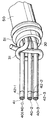
図3は、図2の配線コードにおける端末部を示す斜視図である。
図2の配線コードにおける外被部材50の端末部が所定の長さだけ剥離されて、補強芯線30の端末部と3組の絶縁導体40−1〜40−3の端末部とが露出され、この露出された3組の絶縁導体40−1〜40−3の端末部が、それぞれ溶融金属(例えば、半田等)で結束固定されて固定部42−1〜42−3がそれぞれ形成され、この各絶縁導体40−1〜40−3を構成する複数本の絶縁電線41が、ばらけないようになっている。
FIG. 3 is a perspective view showing a terminal portion of the wiring cord of FIG.
The terminal portion of the
露出された3組の絶縁導体40−1〜40−3は、露出された補強芯線30により結ばれて締結され、この締結部31により3組の絶縁導体40−1〜40−3が結束されている。外被部材50の端末部の周りは、固定部材51により内側へ締め付けられ、外被部材50と補強芯線30及び絶縁導体40−1〜40−3とが結合されている。固定部材51は、環状金具等により形成されている。
The exposed three sets of insulated conductors 40-1 to 40-3 are fastened by being connected by the exposed reinforcing
(実施例1の配線コードの製造例)
図2の3芯用の配線コードを製造する場合、例えば、複数本の絶縁電線41をバンチャーで撚り合わせて各絶縁導体40を形成した後、3組の絶縁導体40−1〜40−3をドラムに巻き取る。ドラムに巻き取られた3組の絶縁導体40−1〜40−3を繰り出し、この3組の絶縁導体40−1〜40−3を所定距離ずらしながら補強芯線30の周りに撚り合わせていき、ドラムに巻き取る。ドラムに巻き取られた補強芯線30及び絶縁導体40−1〜40−3を繰り出し、押出機によって外被部材50で被覆してドラムに巻き取れば、図2の3芯用の配線コードの製造が終了する。
(Example of manufacturing the wiring cord of Example 1)
When manufacturing the three-core wiring cord of FIG. 2, for example, a plurality of
このようにして製造された配線コードを使用する場合、用途に応じて所定の長さに切断する。図3に示すように、切断された配線コードにおける外被部材50の両端末部を、加熱ワイヤ等の切断治具を用いて切断し、この切断した外被部材50を剥離して所定の長さだけ補強芯線30の両端末部及び3組の絶縁導体40(=40−1〜40−3)の両端末部を露出させる。そして、露出した色別の3組の絶縁導体40の両端末部をそれぞれ半田等の溶融金属で結束固定して固定部42−1〜42−3をそれぞれ形成する。これにより、各絶縁導体40を構成する絶縁電線41の両端末部がばらけることを防止できる。
When the wiring cord manufactured in this way is used, it is cut into a predetermined length according to the application. As shown in FIG. 3, both end portions of the
更に、露出した補強芯線30により、露出した3組の絶縁導体40−1〜40−3を結んで締結し、この締結部31により3組の絶縁導体40−1〜40−3を結束する。その後、締め付け治具等を用い、固定部材51により外被部材50の両端末部の周りを内側へ締め付け、外被部材50と補強芯線30及び絶縁導体40−1〜40−3とを結合させれば、図3のような端末構造を有する3芯用の配線コードが得られる。
Furthermore, the exposed three sets of insulated conductors 40-1 to 40-3 are connected and fastened by the exposed reinforcing
このようにして加工された所定の長さの配線コードをヘッドホンやプラグ等に接続する場合、固定部材51付近をヘッドホン等に機械的に固定すると共に、3組の絶縁導体40−1〜40−3における固定部42−1〜42−3を該ヘッドホン等の電極端子に接続すれば、この配線コードによってヘッドホン等の電気信号の伝送が行える。
In the case where the wiring cord having a predetermined length processed in this way is connected to headphones or a plug, the vicinity of the fixing
(実施例1の効果)
本実施例1によれば、次の(1)、(2)のような効果がある。
(Effect of Example 1)
According to the first embodiment, there are the following effects (1) and (2).
(1) 3組の絶縁導体40−1〜40−3は、それぞれ補強芯線を設けずに単に撚り合わせ、この3組の絶縁導体40−1〜40−3を共通の補強芯線30の周りに撚り合わせた構成にしたので、各組の絶縁導体40−1〜40−3におけるインピーダンス等の電気的特性が同一になり、更に、屈曲や引っ張り等に対する機械的強度を大きくしつつ、配線コード径の縮小及び軽量化が可能になる。しかも、各組の絶縁導体40−1〜40−3は、異なる色で区別されているので、イヤホン等に接続する際に、極性の誤りを防止できる。
(1) The three sets of insulated conductors 40-1 to 40-3 are simply twisted without providing reinforcing core wires, and the three sets of insulated conductors 40-1 to 40-3 are arranged around the common reinforcing
(2) 補強芯線30の端末部により、3組の絶縁導体40−1〜40−3の端末部を結んで締結し、更に、固定部材51により、外被部材50の端末部の周りを内側へ締め付ける構成にしたので、外被部材50と補強芯線30及び絶縁導体40−1〜40−3とを強固に結合させることができる。
(2) The terminal portions of the three insulated conductors 40-1 to 40-3 are connected and fastened by the terminal portion of the reinforcing
(実施例2の配線コードの構成)
図4は、本発明の実施例2における配線コードを示す断面図である。
(Configuration of Wiring Cord of Example 2)
FIG. 4 is a cross-sectional view showing a wiring cord in Example 2 of the present invention.
本実施例2の配線コードは、イヤホン・マイクロホン等と携帯オーディオ機器、携帯電話機等とを接続するための配線コード径が例えば1.7mm程度のコードである。この配線コードは、2芯用の第1のコード60と、この第1のコード60に沿って配置された同軸形の第2のコード70とを有し、これらの第1及び第2のコード60,70が、絶縁性の外被部材80により被覆されている。絶縁性の外被部材80は、断面ほぼ円形の管状をなし、軟質性の合成樹脂(例えば、PVC等)により形成されている。
The wiring cord of the second embodiment is a cord having a wiring cord diameter of, for example, about 1.7 mm for connecting an earphone / microphone or the like to a portable audio device, a cellular phone, or the like. This wiring cord has a
第1のコード60は、実施例1の補強芯線30と同様の可撓性の補強芯線61と、この補強芯線61の周りに撚り合わされた実施例1の絶縁導線40と同様の複数組(例えば、2組)の絶縁導体62(=62−1,62−2)とを有している。各組の絶縁導体60(=60−1,60−2)は、実施例1の絶縁導体40と同様に、複数本(例えば、14本)の絶縁電線62aが寄り合わされて異なる色で区別されて構成されている。
The
第2のコード70は、銅線等の金属線からなる導体芯線71を有し、この導体芯線71の周りが、ナイロン等の絶縁性の内被部材72により被覆されている。内被部材72は、断面円形の管状をなし、この周りに、絶縁電線62aと同様の絶縁電線73aが複数本束になって横巻きに巻き付けられて横巻きシールド73が形成されている。
The
(実施例2の配線コードの製造例)
図4の配線コードを製造する場合、例えば、複数本の絶縁電線62aをバンチャーで撚り合わせて各絶縁導体62−1,62−2を形成した後、2組の絶縁導体62−1,62−2をドラムに巻き取る。ドラムに巻き取られた2組の絶縁導体62−1,62−2を繰り出し、この2組の絶縁導体62−1,62−2を所定距離ずらしながら補強芯線61の周りに撚り合わせて第1のコード60を形成していき、ドラムに巻き取る。
(Example of manufacturing the wiring cord of Example 2)
When the wiring cord of FIG. 4 is manufactured, for example, a plurality of insulated wires 62a are twisted with a buncher to form the insulated conductors 62-1 and 62-2, and then two sets of insulated conductors 62-1 and 62- are formed. 2 is wound on a drum. The two sets of insulated conductors 62-1 and 62-2 wound around the drum are fed out, and the two sets of insulated conductors 62-1 and 62-2 are twisted around the reinforcing
又、ドラムに巻き取られた導体芯線71を繰り出し、押出機によって内被部材72で被覆してドラムに巻き取る。ドラムに巻き取られた内被部材72を繰り出し、複数本束になった絶縁電線73aを内被部材72の周りに横巻きに巻き付けて横巻きシールド73を装着することにより、第2のコード70を形成していき、ドラムに巻き取る。
Further, the
その後、ドラムに巻き取られた第1及び第2のコード60,70を繰り出し、押出機によって外被部材80で被覆してドラムに巻き取れば、図4の配線コードの製造が終了する。
Thereafter, the first and
このようにして製造された配線コードを使用する場合、図示しないが、実施例1とほぼ同様に、用途に応じて所定の長さに切断し、例えば、下記のように加工される。 When the wiring cord manufactured in this way is used, although not shown, it is cut into a predetermined length according to the application, and is processed as follows, for example, in substantially the same manner as in the first embodiment.
図4の配線コードにおける外被部材80の端末部を所定の長さだけ剥離し、第1及び第2のコード60,70の端末部を露出する。露出した第1のコード60において、2組の絶縁導体62−1,62−2の端末部を、それぞれ溶融金属(例えば、半田等)で結束固定して固定部をそれぞれ形成する。これにより、各絶縁導体62−1,62−2を構成する複数本の絶縁電線62aが、ばらけないようになっている。更に、露出し2組の絶縁導体62−1,62−2は、露出した補強芯線61により結んで締結し、この締結部により2組の絶縁導体62−1,62−2を結束する。
The terminal portion of the
又、露出した第2のコード70において、横巻きシールド73を構成している束になった複数本の絶縁電線73aの端末部は、ばらけることを防止するために、半田等の溶融金属で結束固定することが望ましい。
Further, in the exposed
その後、環状金具等の固定部材により、外被部材80の端末部の周りを内側へ締め付け、外被部材80と第1及び第2のコード60,70とを結合する。
Thereafter, the periphery of the end portion of the
このようにして加工された所定の長さの配線コードは、例えば、第1のコード60は、音声信号受信用のイヤホン、ヘッドホン等に接続し、第2のコード70は、マイクロホン等に接続して音声信号送信用に使用できる。
For example, the
(実施例2の効果)
本実施例2によれば、次の(1)〜(3)のような効果がある。
(Effect of Example 2)
The second embodiment has the following effects (1) to (3).
(1) 第1のコード60において、実施例1と同様に、2組の絶縁導体62−1,62−2は、それぞれ補強芯線を設けずに単に撚り合わせ、この2組の絶縁導体62−1,62−2を共通の補強芯線61の周りに撚り合わせた構成にしたので、各組の絶縁導体62−1,62−2におけるインピーダンス等の電気的特性が同一になり、更に、屈曲や引っ張り等に対する機械的強度を大きくしつつ、コード径の縮小及び軽量化が可能になる。しかも、各組の絶縁導体62−1,62−2は、異なる色で区別されているので、イヤホン等に接続する際に、極性の誤りを防止できる。
(1) In the
(2) 補強芯線61の端末部により、2組の絶縁導体62−1,62−2の端末部を結んで締結し、更に、図示しない固定部材により、外被部材80の端末部の周りを内側へ締め付ける構成にすれば、外被部材80と第1及び第2のコード60,70とを強固に結合させることができる。
(2) The terminal portions of the two sets of insulated conductors 62-1 and 62-2 are connected and fastened by the terminal portion of the reinforcing
(3) 第1のコード60の他に、同軸形の第2のコード70を有するので、多用途化が可能になる。例えば、第1のコード60は、音声信号受信用に使用し、第2のコード70は、マイクロホン等からの音声信号送信用に使用できる。
(3) Since the coaxial
(変形例)
本発明は、上記実施例1、2に限定されず、種々の利用形態や変形が可能である。この利用形態や変形例としては、例えば、次の(a)〜(c)のようなものがある。
(Modification)
The present invention is not limited to the first and second embodiments, and various usage forms and modifications are possible. For example, the following forms (a) to (c) are available as usage forms and modifications.
(a) 図2の絶縁導体40−1〜40−3の数は、3組に限定されず、2組、あるいは4組、5組、6組等の他の組数に変更し、これに応じて各組を異なる色(例えば、自然色である透明、緑色、赤色、その他の色)に着色して各組を区別する構成にしてもよい。同様に、図4の第1のコード60における絶縁導体62−1,62−2の数は、2組に限定されず、3組、4組、5組、6組等の他の組数に変更し、各組を異なる色に着色して区別する構成にしてもよい。又、各組の絶縁導体40(=40−1〜40−3),62(=62−1,62−2)を形成するための絶縁電線41,62aの材質、断面形状、導体径は、実施例1、2以外のものに変更してもよい。
(A) The number of the insulated conductors 40-1 to 40-3 in FIG. 2 is not limited to three sets, and is changed to other sets such as two sets, four sets, five sets, six sets, etc. Accordingly, each set may be distinguished by coloring each set in a different color (for example, natural, transparent, green, red, and other colors). Similarly, the number of the insulated conductors 62-1 and 62-2 in the
(b) 図4の第2のコード70において、横巻きシールド73に代えて、絶縁電線73aにより編まれた編組シールドを設けてもよい。
(B) In the
(c) 図2及び図4の配線コードの断面構造、寸法、構成材料、製造方法等は、実施例1、2のものに限定されず、種々の変更が可能である。 (C) The cross-sectional structure, dimensions, constituent materials, manufacturing method, and the like of the wiring cords of FIGS. 2 and 4 are not limited to those of the first and second embodiments, and various changes can be made.
30,61 補強芯線
31 締結部
40,40−1〜40−3,62,62−1,62−2 絶縁導体
41,62a,73a 絶縁電線
50,80 外被部材
51 固定部材
60,70 コード
71 導体芯線
72 内被部材
73 横巻きシールド
30, 61 Reinforcing
Claims (7)
前記補強芯線の周りに撚り合わされた複数組の絶縁導体と、
前記複数組の絶縁導体を被覆する絶縁性の外被部材とを有し、
前記各組の絶縁導体は、複数本の絶縁電線が寄り合わされて異なる色で区別されていることを特徴とする配線コード。 A flexible reinforcing core;
A plurality of sets of insulated conductors twisted around the reinforcing core; and
An insulating sheath member covering the plurality of sets of insulated conductors,
Each of the sets of insulated conductors is characterized in that a plurality of insulated wires are arranged close to each other and distinguished by different colors.
前記外被部材の端末部が所定の長さだけ剥離されて前記補強芯線の端末部及び前記複数組の絶縁導体の端末部が露出され、露出された前記複数組の絶縁導体の端末部がそれぞれ溶融金属で結束固定された複数組の固定部と、
露出された前記補強芯線により、露出された前記複数組の絶縁導体を締結する締結部と、
前記外被部材の端末部の周りを内側へ締め付ける固定部材と、
を有することを特徴とする配線コード。 The wiring cord according to claim 1, further comprising:
The terminal portions of the jacket member are peeled by a predetermined length, the terminal portions of the reinforcing core wires and the terminal portions of the plurality of sets of insulated conductors are exposed, and the exposed terminal portions of the plurality of sets of insulated conductors are respectively exposed. A plurality of sets of fixed portions that are bound and fixed with molten metal;
Fastening portions that fasten the exposed plurality of sets of insulated conductors with the exposed reinforcing core wire;
A fixing member that tightens the periphery of the terminal portion of the jacket member inward;
A wiring cord comprising:
前記第1のコードに沿って配置された第2のコードと、
前記第1及び第2のコードを被覆する絶縁性の外被部材とを有する配線コードであって、
前記第1のコードは、
可撓性の補強芯線と、前記補強芯線の周りに撚り合わされた複数組の絶縁導体とを有し、前記各組の絶縁導体は、複数本の絶縁電線が寄り合わされて異なる色で区別されて構成され、
前記第2のコードは、
導体芯線と、前記導体芯線を被覆する絶縁性の内被部材と、前記内被部材の周りに絶縁電線が巻き付けられて形成されたシールドとにより構成されていることを特徴とする配線コード。 A first code;
A second cord disposed along the first cord;
A wiring cord having an insulating jacket member covering the first and second cords;
The first code is:
A flexible reinforcing core wire and a plurality of sets of insulated conductors twisted around the reinforcing core wire, and each set of insulated conductors is distinguished by different colors by a plurality of insulated wires facing each other. Configured,
The second code is:
A wiring cord comprising a conductor core wire, an insulating inner covering member that covers the conductor core wire, and a shield formed by winding an insulated wire around the inner covering member.
Priority Applications (3)
| Application Number | Priority Date | Filing Date | Title |
|---|---|---|---|
| JP2009137088A JP4889764B2 (en) | 2009-06-08 | 2009-06-08 | Wiring cord |
| US12/560,291 US20100307789A1 (en) | 2009-06-08 | 2009-09-15 | Cord |
| DE102009042322A DE102009042322A1 (en) | 2009-06-08 | 2009-09-21 | electric wire |
Applications Claiming Priority (1)
| Application Number | Priority Date | Filing Date | Title |
|---|---|---|---|
| JP2009137088A JP4889764B2 (en) | 2009-06-08 | 2009-06-08 | Wiring cord |
Publications (2)
| Publication Number | Publication Date |
|---|---|
| JP2010282921A true JP2010282921A (en) | 2010-12-16 |
| JP4889764B2 JP4889764B2 (en) | 2012-03-07 |
Family
ID=43049406
Family Applications (1)
| Application Number | Title | Priority Date | Filing Date |
|---|---|---|---|
| JP2009137088A Expired - Fee Related JP4889764B2 (en) | 2009-06-08 | 2009-06-08 | Wiring cord |
Country Status (3)
| Country | Link |
|---|---|
| US (1) | US20100307789A1 (en) |
| JP (1) | JP4889764B2 (en) |
| DE (1) | DE102009042322A1 (en) |
Cited By (2)
| Publication number | Priority date | Publication date | Assignee | Title |
|---|---|---|---|---|
| KR200467282Y1 (en) * | 2011-11-15 | 2013-06-04 | (주)로프캠프 | Assembly means for protecting cable |
| CN105529081A (en) * | 2016-01-23 | 2016-04-27 | 安徽瑞昊缆业有限公司 | Industrial shielded stretching-resistant control cable |
Families Citing this family (5)
| Publication number | Priority date | Publication date | Assignee | Title |
|---|---|---|---|---|
| JP5595877B2 (en) * | 2009-11-23 | 2014-09-24 | シンジャン・ティアンディ・グループ | Earphone wire |
| JP5604157B2 (en) * | 2010-04-06 | 2014-10-08 | エス・ディ・ケイ株式会社 | Wiring cord |
| EP3178030B1 (en) * | 2014-08-06 | 2020-09-16 | Waitak Labels Factory Limited | Authentication devices |
| GB2529434B (en) * | 2014-08-19 | 2016-07-13 | Reid Heath Ltd | In-ear headphone cable |
| EP4002393A1 (en) * | 2020-11-18 | 2022-05-25 | Delta Plus Co., Ltd. | Composite electric wire and method for manufacturing composite electric wire |
Citations (4)
| Publication number | Priority date | Publication date | Assignee | Title |
|---|---|---|---|---|
| JPS5879814A (en) * | 1981-11-02 | 1983-05-13 | Kasei Optonix Co Ltd | Fluorescent substance of zinc sulfide |
| JPS6069420A (en) * | 1983-08-30 | 1985-04-20 | Mitsubishi Heavy Ind Ltd | Combustion controller |
| JPH05174638A (en) * | 1991-12-24 | 1993-07-13 | Nippon Telegr & Teleph Corp <Ntt> | Litz wire and manufacture thereof |
| JP2008300078A (en) * | 2007-05-29 | 2008-12-11 | Sdk Kk | Cabling cord and portable audio system using it |
Family Cites Families (9)
| Publication number | Priority date | Publication date | Assignee | Title |
|---|---|---|---|---|
| US3126442A (en) * | 1964-03-24 | Extensible electric cable | ||
| US3014087A (en) * | 1957-12-17 | 1961-12-19 | Kaplan Philip | Extensible electric cables |
| ES243190A1 (en) * | 1958-07-19 | 1959-03-01 | Garcia Garcia Toribio | Improvements in the formation of an elastically extensible electric current conducting cable |
| JPS6463010A (en) * | 1987-09-04 | 1989-03-09 | Ngk Insulators Ltd | Traveling filter cloth-type filter press |
| JP4634635B2 (en) * | 2001-04-12 | 2011-02-16 | 旭化成テクノプラス株式会社 | Telescopic wire and manufacturing method thereof |
| JP5041399B2 (en) * | 2006-06-30 | 2012-10-03 | Ltkテクノロジーズ株式会社 | Insulated wire, insulated wire composite wire and shielded wire |
| JP2008269799A (en) * | 2007-04-16 | 2008-11-06 | Ltk Technologies Kk | Parallel flexible cable, and earphone antenna |
| CA2717031C (en) * | 2008-06-25 | 2014-05-13 | Asahi Kasei Fibers Corporation | Elastic signal transmission cable |
| JP5487661B2 (en) * | 2009-03-19 | 2014-05-07 | ソニー株式会社 | Shielded cable |
-
2009
- 2009-06-08 JP JP2009137088A patent/JP4889764B2/en not_active Expired - Fee Related
- 2009-09-15 US US12/560,291 patent/US20100307789A1/en not_active Abandoned
- 2009-09-21 DE DE102009042322A patent/DE102009042322A1/en not_active Withdrawn
Patent Citations (4)
| Publication number | Priority date | Publication date | Assignee | Title |
|---|---|---|---|---|
| JPS5879814A (en) * | 1981-11-02 | 1983-05-13 | Kasei Optonix Co Ltd | Fluorescent substance of zinc sulfide |
| JPS6069420A (en) * | 1983-08-30 | 1985-04-20 | Mitsubishi Heavy Ind Ltd | Combustion controller |
| JPH05174638A (en) * | 1991-12-24 | 1993-07-13 | Nippon Telegr & Teleph Corp <Ntt> | Litz wire and manufacture thereof |
| JP2008300078A (en) * | 2007-05-29 | 2008-12-11 | Sdk Kk | Cabling cord and portable audio system using it |
Cited By (2)
| Publication number | Priority date | Publication date | Assignee | Title |
|---|---|---|---|---|
| KR200467282Y1 (en) * | 2011-11-15 | 2013-06-04 | (주)로프캠프 | Assembly means for protecting cable |
| CN105529081A (en) * | 2016-01-23 | 2016-04-27 | 安徽瑞昊缆业有限公司 | Industrial shielded stretching-resistant control cable |
Also Published As
| Publication number | Publication date |
|---|---|
| US20100307789A1 (en) | 2010-12-09 |
| JP4889764B2 (en) | 2012-03-07 |
| DE102009042322A1 (en) | 2010-12-09 |
Similar Documents
| Publication | Publication Date | Title |
|---|---|---|
| JP4889764B2 (en) | Wiring cord | |
| CN103339690B (en) | Multi-core cable and manufacture method thereof | |
| US20150129278A1 (en) | Round cable | |
| KR20100089395A (en) | Coaxial cable and structure of a plurality of coaxial cables | |
| JP5929484B2 (en) | Multi-core cable and manufacturing method thereof | |
| US10825579B2 (en) | Shielding layer and a cable provides with the shielding layer | |
| JP5787706B2 (en) | Audio cable | |
| KR101913298B1 (en) | Cable structures with insulating tape and systems and methods for making the same | |
| CN104269217B (en) | Optical hybrid cable with profiled soft conductor | |
| US10685765B2 (en) | Cable with operation unit | |
| CN220527364U (en) | Terminal assembly and data line for split intelligent glasses | |
| JP5604157B2 (en) | Wiring cord | |
| JP3071579U (en) | code | |
| JP7435016B2 (en) | Optical-electrical composite cable and method for manufacturing optical-electrical composite cable | |
| JP3193295U (en) | Multi-core cable | |
| CN201549266U (en) | Low-smoke XLPE insulated light-weight thin-wall communication cables for ships | |
| JP2011249088A (en) | Composite cable for communication | |
| CN201741491U (en) | Signal cable | |
| JP3155272U (en) | Composite cable | |
| JP2011228054A (en) | Cable and cable with connector | |
| JP3180648U (en) | Wiring cord and wiring cord with electronic parts | |
| JPH09270207A (en) | Flexible cable with excellent terminal processability | |
| WO2018161737A1 (en) | Metal wire armored optoelectronic hybrid cable | |
| JP2003086028A (en) | Composite cable | |
| JP2023174406A (en) | flat cable |
Legal Events
| Date | Code | Title | Description |
|---|---|---|---|
| A977 | Report on retrieval |
Free format text: JAPANESE INTERMEDIATE CODE: A971007 Effective date: 20110815 |
|
| A131 | Notification of reasons for refusal |
Free format text: JAPANESE INTERMEDIATE CODE: A131 Effective date: 20110823 |
|
| A521 | Written amendment |
Free format text: JAPANESE INTERMEDIATE CODE: A523 Effective date: 20111021 |
|
| TRDD | Decision of grant or rejection written | ||
| A01 | Written decision to grant a patent or to grant a registration (utility model) |
Free format text: JAPANESE INTERMEDIATE CODE: A01 Effective date: 20111115 |
|
| A01 | Written decision to grant a patent or to grant a registration (utility model) |
Free format text: JAPANESE INTERMEDIATE CODE: A01 |
|
| A61 | First payment of annual fees (during grant procedure) |
Free format text: JAPANESE INTERMEDIATE CODE: A61 Effective date: 20111213 |
|
| R150 | Certificate of patent or registration of utility model |
Free format text: JAPANESE INTERMEDIATE CODE: R150 |
|
| FPAY | Renewal fee payment (event date is renewal date of database) |
Free format text: PAYMENT UNTIL: 20141222 Year of fee payment: 3 |
|
| R250 | Receipt of annual fees |
Free format text: JAPANESE INTERMEDIATE CODE: R250 |
|
| LAPS | Cancellation because of no payment of annual fees |