JP2010503473A - Automatic stop cock valve - Google Patents
Automatic stop cock valve Download PDFInfo
- Publication number
- JP2010503473A JP2010503473A JP2009528422A JP2009528422A JP2010503473A JP 2010503473 A JP2010503473 A JP 2010503473A JP 2009528422 A JP2009528422 A JP 2009528422A JP 2009528422 A JP2009528422 A JP 2009528422A JP 2010503473 A JP2010503473 A JP 2010503473A
- Authority
- JP
- Japan
- Prior art keywords
- flow
- fluid
- valve
- line
- air
- Prior art date
- Legal status (The legal status is an assumption and is not a legal conclusion. Google has not performed a legal analysis and makes no representation as to the accuracy of the status listed.)
- Granted
Links
Images


Classifications
-
- A—HUMAN NECESSITIES
- A61—MEDICAL OR VETERINARY SCIENCE; HYGIENE
- A61M—DEVICES FOR INTRODUCING MEDIA INTO, OR ONTO, THE BODY; DEVICES FOR TRANSDUCING BODY MEDIA OR FOR TAKING MEDIA FROM THE BODY; DEVICES FOR PRODUCING OR ENDING SLEEP OR STUPOR
- A61M39/00—Tubes, tube connectors, tube couplings, valves, access sites or the like, specially adapted for medical use
- A61M39/22—Valves or arrangement of valves
- A61M39/24—Check- or non-return valves
-
- F—MECHANICAL ENGINEERING; LIGHTING; HEATING; WEAPONS; BLASTING
- F16—ENGINEERING ELEMENTS AND UNITS; GENERAL MEASURES FOR PRODUCING AND MAINTAINING EFFECTIVE FUNCTIONING OF MACHINES OR INSTALLATIONS; THERMAL INSULATION IN GENERAL
- F16K—VALVES; TAPS; COCKS; ACTUATING-FLOATS; DEVICES FOR VENTING OR AERATING
- F16K15/00—Check valves
- F16K15/14—Check valves with flexible valve members
- F16K15/144—Check valves with flexible valve members the closure elements being fixed along all or a part of their periphery
- F16K15/147—Check valves with flexible valve members the closure elements being fixed along all or a part of their periphery the closure elements having specially formed slits or being of an elongated easily collapsible form
-
- A—HUMAN NECESSITIES
- A61—MEDICAL OR VETERINARY SCIENCE; HYGIENE
- A61M—DEVICES FOR INTRODUCING MEDIA INTO, OR ONTO, THE BODY; DEVICES FOR TRANSDUCING BODY MEDIA OR FOR TAKING MEDIA FROM THE BODY; DEVICES FOR PRODUCING OR ENDING SLEEP OR STUPOR
- A61M39/00—Tubes, tube connectors, tube couplings, valves, access sites or the like, specially adapted for medical use
- A61M39/22—Valves or arrangement of valves
-
- A—HUMAN NECESSITIES
- A61—MEDICAL OR VETERINARY SCIENCE; HYGIENE
- A61F—FILTERS IMPLANTABLE INTO BLOOD VESSELS; PROSTHESES; DEVICES PROVIDING PATENCY TO, OR PREVENTING COLLAPSING OF, TUBULAR STRUCTURES OF THE BODY, e.g. STENTS; ORTHOPAEDIC, NURSING OR CONTRACEPTIVE DEVICES; FOMENTATION; TREATMENT OR PROTECTION OF EYES OR EARS; BANDAGES, DRESSINGS OR ABSORBENT PADS; FIRST-AID KITS
- A61F9/00—Methods or devices for treatment of the eyes; Devices for putting in contact-lenses; Devices to correct squinting; Apparatus to guide the blind; Protective devices for the eyes, carried on the body or in the hand
- A61F9/007—Methods or devices for eye surgery
-
- A—HUMAN NECESSITIES
- A61—MEDICAL OR VETERINARY SCIENCE; HYGIENE
- A61M—DEVICES FOR INTRODUCING MEDIA INTO, OR ONTO, THE BODY; DEVICES FOR TRANSDUCING BODY MEDIA OR FOR TAKING MEDIA FROM THE BODY; DEVICES FOR PRODUCING OR ENDING SLEEP OR STUPOR
- A61M5/00—Devices for bringing media into the body in a subcutaneous, intra-vascular or intramuscular way; Accessories therefor, e.g. filling or cleaning devices, arm-rests
- A61M5/14—Infusion devices, e.g. infusing by gravity; Blood infusion; Accessories therefor
-
- A—HUMAN NECESSITIES
- A61—MEDICAL OR VETERINARY SCIENCE; HYGIENE
- A61M—DEVICES FOR INTRODUCING MEDIA INTO, OR ONTO, THE BODY; DEVICES FOR TRANSDUCING BODY MEDIA OR FOR TAKING MEDIA FROM THE BODY; DEVICES FOR PRODUCING OR ENDING SLEEP OR STUPOR
- A61M5/00—Devices for bringing media into the body in a subcutaneous, intra-vascular or intramuscular way; Accessories therefor, e.g. filling or cleaning devices, arm-rests
- A61M5/36—Devices for bringing media into the body in a subcutaneous, intra-vascular or intramuscular way; Accessories therefor, e.g. filling or cleaning devices, arm-rests with means for eliminating or preventing injection or infusion of air into body
-
- A—HUMAN NECESSITIES
- A61—MEDICAL OR VETERINARY SCIENCE; HYGIENE
- A61M—DEVICES FOR INTRODUCING MEDIA INTO, OR ONTO, THE BODY; DEVICES FOR TRANSDUCING BODY MEDIA OR FOR TAKING MEDIA FROM THE BODY; DEVICES FOR PRODUCING OR ENDING SLEEP OR STUPOR
- A61M39/00—Tubes, tube connectors, tube couplings, valves, access sites or the like, specially adapted for medical use
- A61M39/22—Valves or arrangement of valves
- A61M39/24—Check- or non-return valves
- A61M2039/2426—Slit valve
-
- A—HUMAN NECESSITIES
- A61—MEDICAL OR VETERINARY SCIENCE; HYGIENE
- A61M—DEVICES FOR INTRODUCING MEDIA INTO, OR ONTO, THE BODY; DEVICES FOR TRANSDUCING BODY MEDIA OR FOR TAKING MEDIA FROM THE BODY; DEVICES FOR PRODUCING OR ENDING SLEEP OR STUPOR
- A61M39/00—Tubes, tube connectors, tube couplings, valves, access sites or the like, specially adapted for medical use
- A61M39/22—Valves or arrangement of valves
- A61M39/24—Check- or non-return valves
- A61M2039/2493—Check valve with complex design, e.g. several inlets and outlets and several check valves in one body
-
- Y—GENERAL TAGGING OF NEW TECHNOLOGICAL DEVELOPMENTS; GENERAL TAGGING OF CROSS-SECTIONAL TECHNOLOGIES SPANNING OVER SEVERAL SECTIONS OF THE IPC; TECHNICAL SUBJECTS COVERED BY FORMER USPC CROSS-REFERENCE ART COLLECTIONS [XRACs] AND DIGESTS
- Y10—TECHNICAL SUBJECTS COVERED BY FORMER USPC
- Y10T—TECHNICAL SUBJECTS COVERED BY FORMER US CLASSIFICATION
- Y10T137/00—Fluid handling
- Y10T137/7722—Line condition change responsive valves
- Y10T137/7837—Direct response valves [i.e., check valve type]
- Y10T137/7879—Resilient material valve
- Y10T137/788—Having expansible port
- Y10T137/7882—Having exit lip
- Y10T137/7883—With biasing means
-
- Y—GENERAL TAGGING OF NEW TECHNOLOGICAL DEVELOPMENTS; GENERAL TAGGING OF CROSS-SECTIONAL TECHNOLOGIES SPANNING OVER SEVERAL SECTIONS OF THE IPC; TECHNICAL SUBJECTS COVERED BY FORMER USPC CROSS-REFERENCE ART COLLECTIONS [XRACs] AND DIGESTS
- Y10—TECHNICAL SUBJECTS COVERED BY FORMER USPC
- Y10T—TECHNICAL SUBJECTS COVERED BY FORMER US CLASSIFICATION
- Y10T137/00—Fluid handling
- Y10T137/8593—Systems
- Y10T137/87571—Multiple inlet with single outlet
- Y10T137/87676—With flow control
- Y10T137/87684—Valve in each inlet
- Y10T137/87692—With common valve operator
Landscapes
- Health & Medical Sciences (AREA)
- Engineering & Computer Science (AREA)
- Heart & Thoracic Surgery (AREA)
- Veterinary Medicine (AREA)
- Animal Behavior & Ethology (AREA)
- Biomedical Technology (AREA)
- Public Health (AREA)
- General Health & Medical Sciences (AREA)
- Life Sciences & Earth Sciences (AREA)
- Hematology (AREA)
- Anesthesiology (AREA)
- Vascular Medicine (AREA)
- General Engineering & Computer Science (AREA)
- Pulmonology (AREA)
- Emergency Medicine (AREA)
- Ophthalmology & Optometry (AREA)
- Mechanical Engineering (AREA)
- Nuclear Medicine, Radiotherapy & Molecular Imaging (AREA)
- Surgery (AREA)
- Infusion, Injection, And Reservoir Apparatuses (AREA)
- Multiple-Way Valves (AREA)
- Check Valves (AREA)
- Preventing Unauthorised Actuation Of Valves (AREA)
- Valve Housings (AREA)
- Pipe Accessories (AREA)
- Taps Or Cocks (AREA)
Abstract
3つの出入口を備えた取付具を具備する流量制御システム。1つの出入口は流体の入口であり、1つの出入口は気体の入口であり、他の1つの出入口は流体と気体のいずれかの出口である。通常閉じている逆流阻止バルブは取付具内に配置されている。逆流阻止バルブは取付具を介する流体の逆流を阻止する。逆流阻止バルブと取付具はまた流体中の泡の形成を最小化あるいは排除する。
【選択図】図4A flow control system comprising a fixture with three ports. One inlet / outlet is a fluid inlet, one inlet / outlet is a gas inlet, and the other inlet / outlet is an outlet for either fluid or gas. A normally closed backflow prevention valve is located in the fixture. The backflow prevention valve prevents backflow of fluid through the fixture. Backflow prevention valves and fittings also minimize or eliminate the formation of bubbles in the fluid.
[Selection] Figure 4
Description
本発明は、流量調整器具に関し、より具体的には、その装置内に逆流阻止バルブを具備する流量調整器具に関する。 The present invention relates to a flow rate adjusting device, and more particularly to a flow rate adjusting device including a backflow prevention valve in the apparatus.
硝子体網膜外科処置のような、異なる流体を使用する医療処置の過程において、異なる気体と液体を使用することは稀である。例えば、硝子体網膜外科処置では、眼の中からの流体を交換してこれを空気に置換する必要がある。 In the course of medical procedures that use different fluids, such as vitreous retinal surgery, it is rare to use different gases and liquids. For example, in a vitreous retinal surgical procedure, it is necessary to exchange fluid from within the eye and replace it with air.
従来の硝子体網膜外科処置システムでは、眼の中からの流体を空気と交換することは、通常、手動で停止コックバルブの位置を変えることによって行われている。停止コックバルブの手動切替によって、外科注入溶液(例えば、テキサス、フォートウォースのアルコン・ラボラトリ社から入手可能なBSS PLUS(商標)眼球内潅注溶液)のような主流体の流れを停止して、空気のような代替流体が流れ始めるようにする。外科注入溶液の流れを停止して、空気を流し始めるときが来たとき、外科医は、手術室で、彼のアシスタント、同僚、手術室看護師、あるいは、手術室技術師に口頭で停止コックバルブの位置を変えるように手助けを求める必要があった。この技術は、外科処置を遅らせ間違いを招くことがある。不注意に停止コックバルブが機能しない位置に回されると、眼の中への流体の流れが阻止されて眼が柔らかくなり、ただでさえ繊細な外科処置をさらに複雑してしまう。あるいは、停止コックバルブを不適当に操作することによって、流体の望まない逆流を引き起こすことになる。 In conventional vitreous retinal surgical systems, exchanging fluid from the eye with air is usually done by manually changing the position of the stopcock valve. Manual switching of the stop cock valve stops the flow of main fluids such as surgical infusion solutions (e.g. BSS PLUS ™ intraocular irrigation solution available from Alcon Laboratories, Fort Worth, Texas) Allow alternative fluids such as air to begin flowing. When it is time to stop the flow of surgical infusion solution and begin to flow air, the surgeon stops verbally on his assistant, colleague, operating room nurse, or operating room technician in the operating room Needed to seek help to change the position. This technique can delay surgery and lead to errors. If the stopcock valve is inadvertently turned to a non-functional position, fluid flow into the eye is blocked and the eye becomes soft, further complicating even delicate surgical procedures. Alternatively, improper operation of the stopcock valve will cause unwanted back flow of fluid.
したがって、この分野において、逆流の可能性がなく、手助けを求める必要がない、硝子体網膜外科医師が外科注入溶液と空気あるいはその他の気体の切替を直接的に制御できる装置と方法の必要性は依然として残っている。さらに、この分野において、停止コックバルブが機能しない位置に回されることによって、手術中に眼が軟化して複雑化する可能性を取除く装置と方法の必要性は依然として残っている。 Therefore, there is a need in the art for a device and method that allows the vitreous retinal surgeon to directly control the switching between the surgical infusion solution and air or other gases without the possibility of backflow and the need for help. Still remains. Furthermore, there remains a need in the art for an apparatus and method that eliminates the possibility of softening and complicating the eye during surgery by turning the stop cock valve to a non-functional position.
開示された本発明によって、硝子体外科医師が、手助けを受ける必要なく、流体の流れを阻止されることによって眼を軟弱化する可能性を生ぜずに、外科注入溶液と空気あるいはその他の気体との間で切替えることができる装置と方法が提供される。 With the disclosed invention, the vitreous surgeon does not need help and does not have the potential to soften the eye by being blocked from fluid flow, and the surgical infusion solution and air or other gases. An apparatus and method are provided that can be switched between.
1つの側面として、開示された本発明は、第一流体の流れの源、第二流体の流れの源、第一流体の流れと第二流体の流れとを切替る手段、第一流体が流れる第一ライン、第二流体が流れる第二ライン、及び、取付具を具備する流量制御装置である。取付具は、第一ライン用の第一入口、第二ライン用の第二入口、第一流体あるいは第二流体用の出口、通常閉じている逆流防止バルブ、及び、受口を具備する。逆流防止バルブは、切替手段が第一流体の流れを第二流体の流れに切替るときに、開くことができる。受口は、受口の内面と逆流防止バルブの外面との間隙の体積を最小化するために、逆流防止バルブの外面と近接して連携する内面を具備している。このような流量制御装置は、第一流体中の空気あるいは気体の泡の形成を最小化あるいは除去する。このことは、特に、硝子体網膜外科処置あるいはその他の医療処置で効果がある。 In one aspect, the disclosed invention includes a first fluid flow source, a second fluid flow source, means for switching between the first fluid flow and the second fluid flow, and the first fluid flows. The flow control device includes a first line, a second line through which a second fluid flows, and a fixture. The fixture includes a first inlet for the first line, a second inlet for the second line, an outlet for the first fluid or the second fluid, a normally closed backflow prevention valve, and a receptacle. The backflow prevention valve can be opened when the switching means switches the flow of the first fluid to the flow of the second fluid. The receptacle has an inner surface that cooperates closely with the outer surface of the backflow prevention valve to minimize the volume of the gap between the inner surface of the receptacle and the outer surface of the backflow prevention valve. Such a flow control device minimizes or eliminates the formation of air or gas bubbles in the first fluid. This is particularly effective in vitreous retinal surgical procedures or other medical procedures.
実施態様の記載との関連で、同様のあるいは対応する部分に同様の参照番号が付されている、以下の図を参照することによって、本発明の自動停止コックバルブをさらによく理解される。
ここで開示される発明は、硝子体網膜外科処置システムと共に使用する場合を記載しているが、処置中に操作者が異なる流体の流れと流れとの間を切替える必要のある医療用及び医療以外用のその他多くの装置と共に開示された発明は使用できることを当該分野の当業者は理解するであろう。さらに、ここでは、開示される発明は、流体の流れから気体の流れへの切替え等との関連で記載しているが、第一流体の流れから第二流体の流れへの切替え等との関連で使用することもできる。 The invention disclosed herein describes a case for use with a vitreous retinal surgical system, but for medical and non-medical purposes where the operator must switch between different fluid flows during the procedure. Those skilled in the art will appreciate that the disclosed invention can be used with many other devices for use. Furthermore, although the disclosed invention is described here in relation to switching from a fluid flow to a gas flow, etc., it is related to switching from a first fluid flow to a second fluid flow, etc. Can also be used.
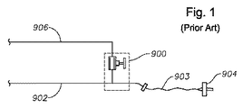
図1に示すように、硝子体網膜外科医師によって使用される従来の流体流システムは、通常、処置中に注入カニューレ904を介して患者の眼に供給される流体を切替える、手動で作動する停止コックバルブ900を備えている。通常の操作中、注入ライン902が開いて空気ライン906が閉じて、外科注入溶液が注入カニューレ904への流れを制御することができる。外科注入溶液の流れから空気の流れへ切替える必要が生じたとき、停止コックバルブ900の位置は手動で切替えられる。既に指摘したように、不注意に外科注入溶液と空気の双方の流れを阻止する位置に動かされたとき、処置中の眼が軟弱化して、ただでさえ繊細な処置がさらに複雑になる。
As shown in FIG. 1, a conventional fluid flow system used by a vitreous retinal surgeon typically has a manually operated stop that switches the fluid delivered to the patient's eye via the
本発明に従って、硝子体網膜外科処置中に外科注入溶液と空気のような流体とを自動的に切替えられることによって、硝子体網膜外科医師は流体の流れの制御の新たなレベルを手にすることができる。外科注入溶液源あるいは圧縮空気からのこのような流体の流れは、フットスイッチに備わった、あるいは、GUI(グラフィカルユーザインターフェイス)上に表示された入力の電気的スイッチを使用して切換えることができる。 In accordance with the present invention, a vitreous retinal surgeon gains a new level of fluid flow control by automatically switching between surgical infusion solution and air-like fluid during a vitreous retinal surgical procedure. Can do. Such fluid flow from the surgical infusion solution source or compressed air can be switched using an input electrical switch on the foot switch or displayed on a GUI (graphical user interface).
図2に示したように、本発明を取入れているシステム10は、従来の手動操作の停止コックバルブ900を、硝子体網膜外科医師が従来の停止コックバルブ900の位置は手動で切替えることなく外科注入溶液の流れと空気その他の気体の流れとの間を切替えることができるように構成されている、自動の停止コックバルブあるいは逆流阻止バルブ20に置き換えている。従来の停止コックバルブ900の位置を手動で切替える必要を取除き、硝子体網膜外科医師が、アシスタント、同僚、手術室看護婦、又は、手術室技師の手助けを借りなくて済むようになり、従来の停止コックバルブ900を手動で機能しない位置へ切替えてしまうことによる流れの中断という潜在的な問題を回避できる。
As shown in FIG. 2, the
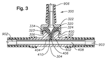
図3にみられるように、本発明の自動停止コックバルブ20の好適な実施態様300はT字型取付具302で取り囲まれている。T字型取付具302は、注入ライン902と空気あるいは気体ライン906の間に配置されている。外科注入溶液が注入ライン902を通って注入カニューレ904へ流れるとき、外科注入溶液はT字型取付具302の直線部分304を通って流れる。外科注入溶液の流れが停止されて空気あるいは気体源が作動したとき、空気がT字型取付具302のステム部分306を通って流れて通常閉じているダックビルバルブ320を開く。T字型取付具302にねじ334で連結されている取付具322によって、通常閉じているダックビルバルブは定位置に保持されている。ダックビル320の2つのくちばし部323、324は、T字型取付具302のステム部306を通る空気の流れから、ダックビルバルブ320の材料であるゴムあるいは柔軟性を持つ物質の弾性によってもたらされるくちばし部323、324の梁の強さに打ち勝つのに十分な力を受けている限り、互いに離れている。空気圧が2つのくちばし部分323、324を互いに離しておくのに十分でなくなったとき、くちばし部323、324は、図3に示すように、くっついてT字型取付具302のステム部306を通る流体の流れを阻止する。
As seen in FIG. 3, a
したがって、図2に示しように注入カニューレ904へ通常の注入がされているとき、外科注入溶液の流れは制御されている。空気ライン906は閉じている。図3に示すように、逆止バルブ20、すなわち、好適な実施態様におけるダックビルバルブ320は、空気ライン906への如何なる外科注入溶液の逆流をも防止する。硝子体網膜外科医師が外科注入溶液の注入から空気の注入への切替えを所望するとき、硝子体網膜外科医師は電動スイッチを入れるかGUIに触れる。外科注入溶液圧は空気あるいは気体の圧力よりも小さい圧力まで減少する、又は、空気あるいは気体の圧力は外科注入溶液圧より大きい圧力まで増加する。これにより、注入ライン902を通る外科注入溶液の流れが終わって空気あるいは気体の流れが開始される。空気あるいは気体の圧力によって、逆止バルブ20を開いて、注入カニューレ904に接続された第三ライン903を通って空気を眼の中に注入することができる。所望すれば、流体の切り替えを逆にすることができ、硝子体網膜外科医師は注入ライン902内で空気あるいは気体から外科注入溶液に戻すように切替えることができる。外科注入溶液の流れから空気あるいは気体の流れにさらに切替えることができるように、さらに、手動で、電気的に、機械的に、あるいは、空気力学的に作動させられるバルブを注入ライン902及び空気ライン906上に配置することもできる。この場合、好適なバルブはピンチバルブである。
Thus, when a normal infusion is being made into the
好適な実施態様においてはダックビルバルブ320が示されているが、本発明を逸脱しないで、この他の逆流阻止バルブを使用することができることを、この分野の当業者は理解するであろう。
Although a
図3に示すように、ステム部306は、バルブ320の外面404の近接して連携する内面402を有する受容部400を備えて形成されている。さらに、バルブ320を流体の流れ内に配置せずに、バルブ320の先端あるいは開口面406はできる限り直線部304のルーメン408の近くに配置されている。このような受容部400のジオメトリ及びバルブ320の配置によって、受容部400と外面404との間の間隙410の体積を最小化あるいは取除いており、このことによって、直線部304内の外科注入溶液の流れの中の空気あるいは気体の泡の形成を防止する。このように空気あるいは気体の泡を防止することで患者の安全性を最大化することができる。
As shown in FIG. 3, the
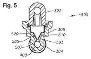
図4−5には、T字型取付具502に取り囲まれた、本発明の自動停止コックバルブ20の第二の好適な実施態様500を示している。好適な実施態様500では、ダックビルバルブ520を受ける受容部501を持つステム部306を採用している。好適な実施態様500は、取付具332が超音波的にステム部306に接着されて、取付部302内のダックビルバルブ320の配置に比較してダックビルバルブ520が90°回転しており、受容部501のジオメトリとダックビルバルブ520がわずかに変更されていることを除き、構造と操作において、好適な実施態様300と実質的に同一である。より具体的には、90°だけダックビルバルブ520を回転して、所望しない、直線部304内の外科注入溶液の流れ内での乱流とこの乱流に伴って生じる空気及び気体の泡を防止することができる。好適な実施態様300と同様に、受容部501は、バルブ520の外面505と近接して連携する内面503を備えている。さらに、バルブ520の先端あるいは開口面507は、バルブ520を流体の流れ内に配置せずに、直線部304のルーメン408のできるだけ近くに配置される。このような受容部501のジオメトリ及びバルブ520の配置によって、受容部501と外面505との間の間隙510の体積を最小化あるいは取除いており、これにより、直線部304内の外科注入溶液の流れの中の空気あるいは気体の泡の形成を防止する。このように空気あるいは気体の泡を防止することで患者の安全性を最大化することができる。
4-5 shows a second
本発明はその好適な実施態様によって図示され記載されたが、以上の開示からこの他の実施態様も可能であることを当該分野の当業者は理解するであろう。そのような他の実施態様は添付の請求項の意味するところと範囲の内に含まれるものとする。 Although the present invention has been illustrated and described by preferred embodiments thereof, those skilled in the art will appreciate from the foregoing disclosure that other embodiments are possible. Such other embodiments are intended to be included within the meaning and scope of the appended claims.
Claims (4)
第一流体の流れの源と、
第二流体の流れの源と、
前記第一流体の前記流れと前記第二流体の前記流れとを切替える手段と、
前記第一流体の前記流れ用の第一ラインと、
前記第二流体の前記流れ用の第二ラインと、
前記第一ライン用の第一入口、前記第二ライン用の第二入口、前記第一流体あるいは前記第二流体のいずれか用の出口、および、前記切替え手段が前記第一流体の前記流れを前記第二流体の前記流れに切替えるとき、開くことができる通常閉じた逆流防止バルブと、
受容部と前記外面との間の間隙の体積を最小化するように前記逆流防止バルブの外面と近接して連携する内面を備えた、受容部とを具備する、流量制御システム。 A flow control system,
A source of the first fluid flow;
A second fluid flow source;
Means for switching between the flow of the first fluid and the flow of the second fluid;
A first line for the flow of the first fluid;
A second line for the flow of the second fluid;
A first inlet for the first line, a second inlet for the second line, an outlet for either the first fluid or the second fluid, and the switching means for the flow of the first fluid. A normally closed backflow prevention valve that can be opened when switching to the flow of the second fluid;
A flow control system comprising a receiving portion with an inner surface that cooperates closely with the outer surface of the backflow prevention valve to minimize the volume of the gap between the receiving portion and the outer surface.
Applications Claiming Priority (5)
| Application Number | Priority Date | Filing Date | Title |
|---|---|---|---|
| US11/522,648 US20080086093A1 (en) | 2006-09-18 | 2006-09-18 | Automatic stop cock valve |
| US11/522,648 | 2006-09-18 | ||
| US11/748,524 US7717129B2 (en) | 2006-09-18 | 2007-05-15 | Automatic stop cock valve |
| US11/748,524 | 2007-05-15 | ||
| PCT/US2007/078101 WO2008036527A2 (en) | 2006-09-18 | 2007-09-11 | Automatic stop cock valve |
Publications (2)
| Publication Number | Publication Date |
|---|---|
| JP2010503473A true JP2010503473A (en) | 2010-02-04 |
| JP5185275B2 JP5185275B2 (en) | 2013-04-17 |
Family
ID=39187314
Family Applications (2)
| Application Number | Title | Priority Date | Filing Date |
|---|---|---|---|
| JP2009528363A Pending JP2010503464A (en) | 2006-09-18 | 2007-07-24 | Automatic stopcock valve |
| JP2009528422A Active JP5185275B2 (en) | 2006-09-18 | 2007-09-11 | Automatic stop cock valve |
Family Applications Before (1)
| Application Number | Title | Priority Date | Filing Date |
|---|---|---|---|
| JP2009528363A Pending JP2010503464A (en) | 2006-09-18 | 2007-07-24 | Automatic stopcock valve |
Country Status (17)
| Country | Link |
|---|---|
| US (2) | US20080086093A1 (en) |
| EP (2) | EP2063932A4 (en) |
| JP (2) | JP2010503464A (en) |
| KR (1) | KR20090075695A (en) |
| CN (2) | CN101516419A (en) |
| AR (2) | AR062547A1 (en) |
| AT (1) | ATE490373T1 (en) |
| AU (2) | AU2007297500A1 (en) |
| BR (2) | BRPI0716861A2 (en) |
| CA (2) | CA2661996A1 (en) |
| DE (1) | DE602007010960D1 (en) |
| ES (1) | ES2354747T3 (en) |
| IL (1) | IL197358A0 (en) |
| MX (2) | MX2009002619A (en) |
| RU (2) | RU2009114698A (en) |
| TW (2) | TW200814980A (en) |
| WO (2) | WO2008036462A2 (en) |
Families Citing this family (47)
| Publication number | Priority date | Publication date | Assignee | Title |
|---|---|---|---|---|
| EP2428171B1 (en) | 2001-09-24 | 2014-02-19 | Applied Medical Resources Corporation | Bladeless Obturator |
| WO2003096879A2 (en) | 2002-05-16 | 2003-11-27 | Applied Medical Resources Corporation | Cone tip obturator |
| EP2545863B1 (en) | 2003-10-03 | 2020-06-17 | Applied Medical Resources Corporation | Bladeless optical obturator |
| EP1765197B1 (en) | 2004-06-29 | 2017-03-29 | Applied Medical Resources Corporation | Insufflating optical surgical instrument |
| US20060212037A1 (en) * | 2005-03-16 | 2006-09-21 | Alcon, Inc. | Pumping chamber for a liquefaction handpiece |
| US7758585B2 (en) * | 2005-03-16 | 2010-07-20 | Alcon, Inc. | Pumping chamber for a liquefaction handpiece |
| JP4871019B2 (en) * | 2006-05-15 | 2012-02-08 | 日本コヴィディエン株式会社 | Liquid infusion tool |
| EP2984993B1 (en) | 2006-10-06 | 2019-09-11 | Applied Medical Resources Corporation | Visual insufflation port |
| US7849875B2 (en) * | 2007-07-31 | 2010-12-14 | Alcon, Inc. | Check valve |
| US20090032121A1 (en) * | 2007-07-31 | 2009-02-05 | Chon James Y | Check Valve |
| EP2851020B1 (en) | 2008-01-25 | 2016-01-20 | Applied Medical Resources Corporation | Insufflating access system |
| US8291933B2 (en) | 2008-09-25 | 2012-10-23 | Novartis Ag | Spring-less check valve for a handpiece |
| EP3545883B1 (en) | 2008-09-29 | 2021-01-13 | Applied Medical Resources Corporation | First-entry trocar system |
| KR101122531B1 (en) * | 2009-04-13 | 2012-03-15 | (주)이화프레지니우스카비 | Device of charging medical liguid and controlling flow thereof and medical liquid injection apparatus comprising the same |
| JP5476176B2 (en) * | 2010-03-23 | 2014-04-23 | 未来工業株式会社 | Drain valve |
| US8689439B2 (en) | 2010-08-06 | 2014-04-08 | Abbott Laboratories | Method for forming a tube for use with a pump delivery system |
| US8377001B2 (en) | 2010-10-01 | 2013-02-19 | Abbott Laboratories | Feeding set for a peristaltic pump system |
| US8377000B2 (en) | 2010-10-01 | 2013-02-19 | Abbott Laboratories | Enteral feeding apparatus having a feeding set |
| JP6066428B2 (en) | 2011-05-02 | 2017-01-25 | アプライド メディカル リソーシーズ コーポレイション | Low profile surgical universal access port |
| EP2714183A2 (en) | 2011-05-24 | 2014-04-09 | Sanofi-Aventis Deutschland GmbH | Check valve arrangement |
| KR102170110B1 (en) | 2011-12-08 | 2020-10-28 | 알콘 인코포레이티드 | Selectively moveable valve elements for aspiration and irrigation circuits |
| US9814866B1 (en) | 2012-05-31 | 2017-11-14 | Gaurav K Goswami | Flushable drainage device and method of use |
| CN102935256A (en) * | 2012-12-05 | 2013-02-20 | 山东威高集团医用高分子制品股份有限公司 | One-way valve for infusion |
| KR101373780B1 (en) * | 2012-12-28 | 2014-03-13 | 주식회사 파워록 | Check valve for vehicle using gas |
| US9604184B2 (en) | 2013-03-06 | 2017-03-28 | Orthovita, Inc. | Mixing system and valve assembly |
| US9549850B2 (en) | 2013-04-26 | 2017-01-24 | Novartis Ag | Partial venting system for occlusion surge mitigation |
| KR101504453B1 (en) * | 2014-02-20 | 2015-03-19 | 방병훈 | Backflow prevention system |
| AU2015226289B8 (en) | 2014-03-05 | 2019-10-31 | Fraunhofer-Gesellschaft zur Förderung der angewandten Forschung e.V. | Device for providing a constant amount of aerosol |
| GB201418620D0 (en) * | 2014-10-20 | 2014-12-03 | Mcalpine & Co Ltd | In-line valve |
| CN104288861A (en) * | 2014-10-20 | 2015-01-21 | 贾宇东 | Two-channel gradient one-way single-flow-direction time-delay inverse resistance device |
| GB2552659B (en) | 2016-08-01 | 2019-06-12 | Mcalpine & Co Ltd | High flow drain control |
| KR101689233B1 (en) * | 2016-08-05 | 2017-01-02 | 주식회사 세종메디칼 | Medicinal fluid flow indicator and fluid infusion pump having the same |
| SI3312481T1 (en) | 2016-10-18 | 2020-04-30 | Frenzelit Gmbh | Method for unique and captive marking and identifying of a soft seal material |
| US11045353B2 (en) | 2017-05-24 | 2021-06-29 | Alcon Inc. | Ophthalmic surgical system with infusion fluid and substance delivery through an infusion cannula |
| JP6870539B2 (en) * | 2017-08-30 | 2021-05-12 | 豊田合成株式会社 | Pipe fitting |
| CN108523966B (en) * | 2018-04-10 | 2021-01-01 | 杭州维力医疗器械有限公司 | Multifunctional sinus dilation treatment system |
| KR101891223B1 (en) * | 2018-05-10 | 2018-08-23 | 최숙녀 | Filter assembly for interior and safety syringe using the same |
| KR102247794B1 (en) * | 2018-10-24 | 2021-05-04 | 김연주 | Stopcock |
| CN110052055A (en) * | 2019-01-10 | 2019-07-26 | 苏州瑞倍成机械设备有限公司 | It is a kind of to have the boiling type closed loop crystallizer stirred from suction functional bands |
| CN110464909A (en) * | 2019-08-26 | 2019-11-19 | 湖南丹尼尔智能科技有限公司 | A kind of transfusion apparatus for facilitating coutroi velocity anti-return that can remind using overflow valve |
| US12076530B2 (en) * | 2019-09-27 | 2024-09-03 | Engain | Apparatus for preventing backflow |
| CA3165419A1 (en) * | 2020-01-27 | 2021-08-05 | John Picot | Rotating luer connector |
| CN111282500B (en) * | 2020-02-12 | 2021-09-24 | 佛山市鼎科科技发展有限公司 | A kind of anti-caking hydroponic nutrient solution automatic preparation equipment |
| WO2022130213A1 (en) | 2020-12-17 | 2022-06-23 | Alcon Inc. | Automatic infusion valve |
| NL2032219B1 (en) * | 2022-06-20 | 2024-01-08 | Crea Ip B V | Injector device |
| CN121941464A (en) * | 2023-10-02 | 2026-04-28 | 阿皮克斯医疗股份有限公司 | Electrosurgical device with irrigation port |
| US12607274B2 (en) * | 2023-11-11 | 2026-04-21 | Zhongshan Peili Technology Co., Ltd. | Fuel pump flow passage structure |
Citations (2)
| Publication number | Priority date | Publication date | Assignee | Title |
|---|---|---|---|---|
| JPS6095281A (en) * | 1983-09-26 | 1985-05-28 | ヴアーネイ・ラボラトリーズ・インコーポレーテツド | Valve assembly |
| JPH1189871A (en) * | 1997-09-17 | 1999-04-06 | Nidek Co Ltd | Gas supplying device for ophthalmic operation, and ophthalmic operation device provided with the same |
Family Cites Families (26)
| Publication number | Priority date | Publication date | Assignee | Title |
|---|---|---|---|---|
| US1686310A (en) * | 1928-04-14 | 1928-10-02 | Edward M Beebe | Slush-pump manifold |
| US1795386A (en) * | 1928-10-08 | 1931-03-10 | Edward M Beebe | Pump-manifold valve |
| US2551045A (en) * | 1944-09-07 | 1951-05-01 | Parker Appliance Co | Shuttle valve |
| US3572375A (en) * | 1967-06-02 | 1971-03-23 | David Rosenberg | Twin valve t-connector |
| GB1262146A (en) * | 1968-03-05 | 1972-02-02 | Pall Corp | Twin valve connector |
| US3706355A (en) * | 1971-06-21 | 1972-12-19 | Edgar C Oglesbee | Reservoir for lubricating pneumatic components |
| US3972343A (en) * | 1974-11-13 | 1976-08-03 | Parker-Hannifin Corporation | Shuttle valve |
| SE388358B (en) * | 1975-01-24 | 1976-10-04 | Stille Werner Ab | CANYLE UNIT |
| US4034754A (en) * | 1975-08-07 | 1977-07-12 | Baxter Travenol Laboratories, Inc. | Intravenous solution set having a constricted inner diameter portion |
| US4405316A (en) * | 1978-04-03 | 1983-09-20 | Baxter Travenol Laboratories, Inc. | Injection site with check valve inlet |
| US4612960A (en) * | 1985-02-21 | 1986-09-23 | Vernay Laboratories, Inc. | Valve assembly |
| DE3815396A1 (en) | 1988-05-05 | 1989-11-16 | Hartwig Straub | 3-WAY VALVE |
| US5066393A (en) * | 1989-08-28 | 1991-11-19 | Culligan International Company | Slotted flow collector/distributor for water treatment tank with one-way valves |
| US5098405A (en) * | 1991-01-31 | 1992-03-24 | Becton, Dickinson And Company | Apparatus and method for a side port cathether adapter with a one piece integral combination valve |
| US5285808A (en) * | 1992-11-05 | 1994-02-15 | Clanin & Associates | Diverting relief valve backflow |
| US5261459A (en) * | 1992-12-07 | 1993-11-16 | Vernay Laboratories, Inc. | Miniature duckbill valve having a low cracking pressure and high flow rate |
| US5383485A (en) * | 1993-12-13 | 1995-01-24 | Lai; Herman | Valve for three-way tubings |
| US5449051A (en) * | 1993-12-16 | 1995-09-12 | Liao; Pen-Huai | Pneumatic oil lubricator |
| US5512043A (en) * | 1994-03-03 | 1996-04-30 | Level 1 Technologies | Needleless injection site |
| US5836484A (en) * | 1996-10-03 | 1998-11-17 | Gerber; Bernard R. | Contamination-safe multiple-dose dispensing cartridge for flowable materials |
| CN2412583Y (en) * | 1998-08-05 | 2001-01-03 | 张九弘 | Once-used transfusion system and hanger threrfor |
| RU2155627C1 (en) * | 1999-10-25 | 2000-09-10 | Ратников Виктор Иванович | Plant for automatic and mechanized filtering and transfer of various liquids |
| US6257268B1 (en) * | 1999-12-01 | 2001-07-10 | Gilmore Valve Company | Pressure biased shuttle valve |
| JP2006504455A (en) * | 2002-10-29 | 2006-02-09 | バソジェン アイルランド リミテッド | Apparatus and method for controlling the release of gas from a medical fluid |
| US7601141B2 (en) * | 2002-11-26 | 2009-10-13 | Nexus Medical, Llc | Pressure actuated flow control valve |
| US7670322B2 (en) * | 2005-02-01 | 2010-03-02 | Icu Medical, Inc. | Check valve for medical Y-site |
-
2006
- 2006-09-18 US US11/522,648 patent/US20080086093A1/en not_active Abandoned
-
2007
- 2007-05-15 US US11/748,524 patent/US7717129B2/en active Active
- 2007-07-24 AU AU2007297500A patent/AU2007297500A1/en not_active Abandoned
- 2007-07-24 RU RU2009114698/14A patent/RU2009114698A/en unknown
- 2007-07-24 KR KR1020097007980A patent/KR20090075695A/en not_active Withdrawn
- 2007-07-24 CN CNA2007800346309A patent/CN101516419A/en active Pending
- 2007-07-24 CA CA 2661996 patent/CA2661996A1/en not_active Abandoned
- 2007-07-24 EP EP07813252A patent/EP2063932A4/en not_active Withdrawn
- 2007-07-24 JP JP2009528363A patent/JP2010503464A/en active Pending
- 2007-07-24 MX MX2009002619A patent/MX2009002619A/en not_active Application Discontinuation
- 2007-07-24 WO PCT/US2007/074172 patent/WO2008036462A2/en not_active Ceased
- 2007-07-27 BR BRPI0716861-6A patent/BRPI0716861A2/en not_active Application Discontinuation
- 2007-07-31 TW TW96127984A patent/TW200814980A/en unknown
- 2007-08-27 AR ARP070103792 patent/AR062547A1/en unknown
- 2007-09-11 JP JP2009528422A patent/JP5185275B2/en active Active
- 2007-09-11 AU AU2007297467A patent/AU2007297467B2/en active Active
- 2007-09-11 WO PCT/US2007/078101 patent/WO2008036527A2/en not_active Ceased
- 2007-09-11 BR BRPI0716851A patent/BRPI0716851B8/en active IP Right Grant
- 2007-09-11 MX MX2009002586A patent/MX2009002586A/en active IP Right Grant
- 2007-09-11 RU RU2009114717/14A patent/RU2449817C2/en active
- 2007-09-11 EP EP20070842205 patent/EP2069580B1/en active Active
- 2007-09-11 ES ES07842205T patent/ES2354747T3/en active Active
- 2007-09-11 DE DE200760010960 patent/DE602007010960D1/en active Active
- 2007-09-11 CN CN2007800346188A patent/CN101517169B/en active Active
- 2007-09-11 AT AT07842205T patent/ATE490373T1/en not_active IP Right Cessation
- 2007-09-11 CA CA2662360A patent/CA2662360C/en active Active
- 2007-09-17 TW TW96134681A patent/TWI439301B/en not_active IP Right Cessation
- 2007-09-18 AR ARP070104115 patent/AR062878A1/en not_active Application Discontinuation
-
2009
- 2009-03-02 IL IL197358A patent/IL197358A0/en unknown
Patent Citations (2)
| Publication number | Priority date | Publication date | Assignee | Title |
|---|---|---|---|---|
| JPS6095281A (en) * | 1983-09-26 | 1985-05-28 | ヴアーネイ・ラボラトリーズ・インコーポレーテツド | Valve assembly |
| JPH1189871A (en) * | 1997-09-17 | 1999-04-06 | Nidek Co Ltd | Gas supplying device for ophthalmic operation, and ophthalmic operation device provided with the same |
Also Published As
Similar Documents
| Publication | Publication Date | Title |
|---|---|---|
| JP5185275B2 (en) | Automatic stop cock valve | |
| US20080077077A1 (en) | Valve that is normally closed in the free state | |
| AU2013266899B2 (en) | Surgical handpiece having directional fluid control capabilities | |
| US20250367359A1 (en) | Automatic infusion valve | |
| KR101216573B1 (en) | Automatic stop cock valve | |
| US20250360026A1 (en) | Injector device | |
| CN119971290A (en) | Interventional operation fluid pipeline system |
Legal Events
| Date | Code | Title | Description |
|---|---|---|---|
| A621 | Written request for application examination |
Free format text: JAPANESE INTERMEDIATE CODE: A621 Effective date: 20100901 |
|
| A977 | Report on retrieval |
Free format text: JAPANESE INTERMEDIATE CODE: A971007 Effective date: 20120712 |
|
| A131 | Notification of reasons for refusal |
Free format text: JAPANESE INTERMEDIATE CODE: A131 Effective date: 20120724 |
|
| A521 | Request for written amendment filed |
Free format text: JAPANESE INTERMEDIATE CODE: A523 Effective date: 20121023 |
|
| TRDD | Decision of grant or rejection written | ||
| A01 | Written decision to grant a patent or to grant a registration (utility model) |
Free format text: JAPANESE INTERMEDIATE CODE: A01 Effective date: 20121218 |
|
| A61 | First payment of annual fees (during grant procedure) |
Free format text: JAPANESE INTERMEDIATE CODE: A61 Effective date: 20130117 |
|
| R150 | Certificate of patent or registration of utility model |
Ref document number: 5185275 Country of ref document: JP Free format text: JAPANESE INTERMEDIATE CODE: R150 Free format text: JAPANESE INTERMEDIATE CODE: R150 |
|
| FPAY | Renewal fee payment (event date is renewal date of database) |
Free format text: PAYMENT UNTIL: 20160125 Year of fee payment: 3 |
|
| R250 | Receipt of annual fees |
Free format text: JAPANESE INTERMEDIATE CODE: R250 |
|
| R250 | Receipt of annual fees |
Free format text: JAPANESE INTERMEDIATE CODE: R250 |
|
| R250 | Receipt of annual fees |
Free format text: JAPANESE INTERMEDIATE CODE: R250 |
|
| R250 | Receipt of annual fees |
Free format text: JAPANESE INTERMEDIATE CODE: R250 |
|
| S111 | Request for change of ownership or part of ownership |
Free format text: JAPANESE INTERMEDIATE CODE: R313111 Free format text: JAPANESE INTERMEDIATE CODE: R313113 |
|
| R250 | Receipt of annual fees |
Free format text: JAPANESE INTERMEDIATE CODE: R250 |
|
| S111 | Request for change of ownership or part of ownership |
Free format text: JAPANESE INTERMEDIATE CODE: R313111 Free format text: JAPANESE INTERMEDIATE CODE: R313113 |
|
| R350 | Written notification of registration of transfer |
Free format text: JAPANESE INTERMEDIATE CODE: R350 |
|
| R250 | Receipt of annual fees |
Free format text: JAPANESE INTERMEDIATE CODE: R250 |
|
| R250 | Receipt of annual fees |
Free format text: JAPANESE INTERMEDIATE CODE: R250 |
|
| R250 | Receipt of annual fees |
Free format text: JAPANESE INTERMEDIATE CODE: R250 |
|
| R250 | Receipt of annual fees |
Free format text: JAPANESE INTERMEDIATE CODE: R250 |
|
| R250 | Receipt of annual fees |
Free format text: JAPANESE INTERMEDIATE CODE: R250 |
|
| R250 | Receipt of annual fees |
Free format text: JAPANESE INTERMEDIATE CODE: R250 |